Table of Contents
Advertisement
Available languages
Available languages
Advertisement
Table of Contents

Related Manuals for emmeti 01350340


Summary of Contents for emmeti 01350340
- Page 1 IT IT...
- Page 2 Produit certifié CEN conformément à UNI EN 215 pour les associations: CEN zertifiziertes Produkt gemäß UNI EN 215 für die Ergänzungen: Produto certificado CEN em conformidade com UNI EN 215 para as combinações: Codice/Code/Código/Code Codice/Code/Código/Code Code/Código Code/Código 01213040 01350340 01213054 01350342 01213046 01350344 9645P500 01350346 01213052 01350348...
- Page 3 .........4 IT IT ........21 ........38 ........55 ........72 ........89...
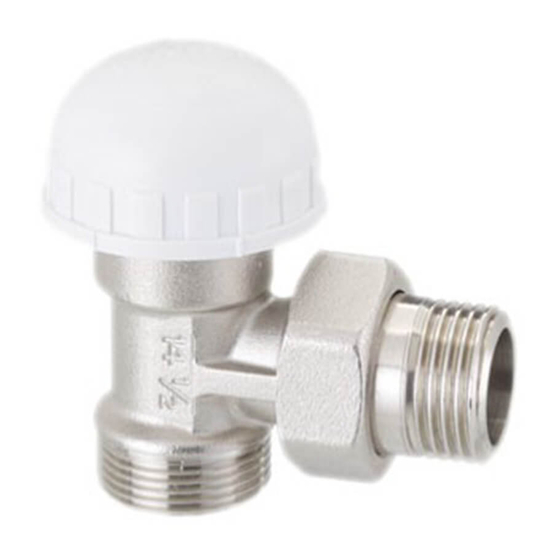
- Page 4 Corpo valvola con otturatore Testa di regolazione/manopola Indice di riferimento temperatura Ghiera di fissaggio Fermi Cappuccio in plastica Esagono...
- Page 5 Istruzioni per l’installazione Descrizione componenti Le valvole termostatiche sono costituite principalmente da due elementi: Corpo valvola Provvisto di otturatore con elemento di tenuta che non richie- de manutenzione; Testa di regolazione termostatica La testa di regolazione termostatica è dotata di un elemento sensibile contenente un fluido con un determinato coefficien- te di dilatazione.
- Page 6 2 Montaggio del corpo valvola 1 Le tubazioni dell’impianto devono essere pulite da tutti i corpi estranei. 2 I radiatori e l’impianto di riscaldamento devono essere sciacquati. Attenzione La via d’acqua nei corpi valvola può essere aperta o chiusa uti- lizzando il coperchio di protezione ...
- Page 7 Montaggio della testa Attenzione La testa di regolazione termostatica non deve essere mai in- stallata in posizione verticale: questo ne pregiudicherebbe la sensibilità alla temperatura. 1 Girare la manopola della testa di regolazione fino alla posi- zione di temperatura più alta: posizione 5. 2 Accoppiare la testa di regolazione con la valvola premen- dola fino a battuta sul corpo valvola, osservando che l’indi- ce di riferimento temperatura ...
- Page 8 Test di funzionamento Montata la testa di regolazione termostatica, si deve eseguire un test di funzionamento. 1 Girare la manopola fino alla posizione 0. 2 Mettere in funzione il riscaldamento e verificare che il radia- tore rimanga freddo. 3 Girare la manopola fino alla posizione 5 e verificare che il ra- diatore si riscaldi.
- Page 9 6 Impostazione della temperatura ambiente desiderata La manopola della testa di regolazione permette l’impostazio- ne della temperatura ambiente desiderata. Sulla manopola è riportata una scala con valori da 0 a 5. Ognuno di questi numeri corrisponde ad una determinata tempe- ratura.
- Page 10 Il rilevamento della temperatura ambiente La testa con sonda termostatica ha il compito di misurare costan- temente la temperatura ambiente e di trasmettere la misurazione alla valvola di regolazione. Essa deve perciò essere influenzata costantemente dall’aria cir- colante nell’ambiente. Attenzione Attorno alla sonda termostatica non deve formarsi un ristagno di aria dovuto alla copertura della stessa da parte di spessi rivesti- menti o tende, o per l'applicazione in nicchie profonde, altrimen-...
- Page 11 Limitazioni temperatura La testa di regolazione termostatica è dotata di due fermi amo- vibili , uno rosso ed uno blu, alloggiati sotto all’indice di rife- rimento (vedi figura E). Questi servono per bloccare una temperatura o per limitare il campo di regolazione. ...
- Page 12 8.1 Limitazione della minima temperatura regolabile Se, per qualunque motivo, volete che la manopola della testa termostatica possa essere girata solo fino ad una determinata temperatura, procedete come segue: 1 Sfilare il fermo blu. 2 Impostare la temperatura desiderata (esempio: antigelo posizione 3 Individuare il pallino nero ...
- Page 13 8.2 Limitazione della massima temperatura regolabile Se per motivi di risparmio volete limitare la temperatura ambien- te verso l’alto, procedete come segue: 1 Sfilare il fermo rosso. 2 Impostare la temperatura desiderata (esempio: 20 °C posizione 3). 3 Individuare il pallino nero stampato tra le posizioni 5 e 0 (Fig.
- Page 14 8.3 Bloccaggio di un temperatura fissa Se volete fissare sulla manopola una determinata temperatura desiderata inserite i fermi negli alloggiamenti a destra ed a sini- stra del pallino nero dopo aver impostato la temperatura de- siderata (vedi 8.1 e 8.2). Ad operazione eseguita, la manopola non ruota più.
- Page 15 11 Manutenzione Le teste termostatiche di regolazione non necessitano di manu- tenzione. L’eliminazione di eventuali inconvenienti deve esse- re eseguita seguendo attentamente le istruzioni da parte di un tecnico competente. 12 Inconvenienti Inconveniente Il radiatore non si riscalda. Rimedio • Controllare se il radiatore è spurgato. •...
- Page 16 Inconveniente Il radiatore non si raffredda. Rimedio • Controllare se la testa di regolazione termostatica è montata correttamente. • Controllare che non ci siano particelle di sporcizia nella se- de di chiusura della valvola. Allo scopo, togliere la testa di regolazione e controllare se lo stelo dell’otturatore scorre re- golarmente oppure è...
-
Page 17: Dati Tecnici
13 Dati tecnici Pressione max di esercizio 10 bar Pressione max differenziale di esercizio 0,3 bar* Influenza della pressione differenziale 0,3 K Temperatura max ambiente 40 °C Temperatura max acqua impianto 100 °C Temperatura di stoccaggio da -10 a 50 °C Campo di regolazione 7 ÷... - Page 18 Adattatore per installazione testa termostatica su valvole Tris termostatizzabili Per installare le teste termostatiche sulle valvole Tris termosta- tizzabili procedere nel seguente modo: 1 Con l’ausilio di un cacciavite rimuovere la manopola della val- vola Tris termostatizzabile (vedi figure A e B). 2 Rimuovere la ghiera in plastica (Fig.
- Page 19 Adattatore Fig. C Fig. D Adattatore Fig. E Fig. F...
- Page 20 Trasformazione valvola Poker termostatizzabile Chiave a tubo Ø 19 ...
- Page 21 Valve body with shutter Setting head Temperature reference pointer Fastening ring nut Setting pins Plastic cover Hexagon...
-
Page 22: Installation Instructions
Installation instructions Description components Thermostatic head is mainly composed of two elements: The valve body Supplied with shutter with seal that does not require any main- tenance; The thermostatic setting head The setting head is equipped with a sensitive element contain- ing a fluid with a given coefficient of expansion. - Page 23 2 Assembly of valve body 1 The piping of the system must be clean of any foreign bodies. 2 The radiators and the heating system must be rinsed. Warning The water way in the valve bodies can be opened or closed us- ing the protection lid ...
- Page 24 Assembly of the thermostatic setting head Warning The head must never be installed vertically: this would compro- mise its temperature sensitivity. 1 Turn the thermostatic setting head knob to the highest tem- perature position: position 5. 2 Couple the setting head with the valve, pressing it until it hits the valve body, so that the temperature reference point- er ...
- Page 25 Function test As-the end of the assembly of the thermal expansion valve a function test must be carried out. For this you must proceed as follows: 1 Turn the knob of head till position 0. 2 Turn on the heating system and check that radiator is not heated. 3 Turn the knob of the head till position “5”...
- Page 26 Setting the desired room temperature The thermostatic head rotating knob allows the setting of the room temperature. Numbers from 1 to 5 are maked on the rotating knob. Each on of these numbers corresponds to a determined temper- ature. The distances betwenen the single numers correspond to intermediate temperatures.
- Page 27 Detection of room temperature The head with thermal sensor provides a constant measure of room temperature and the transfer the measurement to the setting valve. It must therefore be influenced constantly by the air circulat- ing in the room. Warning Avoid that air around the thermostatic head is blocked.
- Page 28 Temperature limitation The thermostatic head is provided with two setting pins , one read and the other blue, under the reference index (see Fig. E). These pins are provided to set a temperature or to limit the regulation possibilities. Fig.
- Page 29 8.1 Limiting the minimum adjustable temperature To limit the adjustment of the head knob till a certain low tem- perature, proceed as follows: 1 Remove the blue pin. 2 Set the desired temperature (e.g. antifreeze pos. 3 Find the black dot k located between position 5 and 0 (Fig. G). 4 Push through the pin k into the first hole on the right of the black dot.
- Page 30 8.2 Limiting the maximum adjustable temperature To limit the adjustment of the head knob till a certain high tem- perature, proceed as follows: 1 Remove the red pin. 2 Set the desired temperature. (e.g. 20 °C pos. 3). 3 Find the black dot located between position 5 and 0 (Fig. I). 4 Push through the pin ...
- Page 31 8.3 Locking of a fixed temperature If you desire to set a temperature on the knob please insert the locks in the spaces to the right and to the left of the black point after setting the required temperature (see 8.1 and 8.2) Once the operation is completed the head knob does not ro- tate anymore.
-
Page 32: Troubleshooting
11 Maintenance Head does not need any maintenance. The elimination of any difficulty must be done by a competent technical, following the thermostatic valve assembly instructions. 12 Troubleshooting Inconvenient Radiator is not warming up. Solution • Check if radiator has been vented (air bled off). •... - Page 33 Inconvenient Radiator does not cool off. Solution • Check if thermostatic head has been properly installed. • Check that no foreign objects (dirt particle, a.s.o.) have been entering on the thermostatic valve seat. To verify it, take out the thermostat head from valve, and check if the rod of thermo- static shutter moves freely or is blocked.
-
Page 34: Technical Specification
13 Technical specification Max operating pressure 10 bar Max differential operating pressure 0,3 bar* Differential pressure influence 0,3 K Max environment temperature 40 °C Max temperature of water in the system 100 °C Storage temperature from -15 to 50 °C Setting range 7 ÷... - Page 35 Adapter for thermostatic’s head installation on Tris thermostatizable radiator valve To install thermostatic’s head on Tris thermostatizable Radiator valve proceed as follows: 1 By using a screwdriver remove Tris thermostatizable radia- tor valve’s (see pict. A and B) 2 Remove plastic ring (Fig. C). 3 Insert threaded adapter in the apposite seat (Fig.
- Page 36 Adapter Fig. C Fig. D Adapter Fig. E Fig. F...
- Page 37 How to fit sensor head on Poker thermostatizable Tubular spanner Ø 19 ...
- Page 38 Cuerpo válvula con obturador Cabezal de regulación/manubrio Índice de referencia temperatura Arandela de fijación Topes Capuchón de plástico Hexágono ...
- Page 39 Instrucciones para la instalación Descripción componentes Las válvulas termostáticas están formadas por dos elementos fundamentales: Cuerpo de la válvula Provisto de obturador con elemento de estanquidad que no ne- cesita mantenimiento; Cabezal de regulación termostático El cabezal de regulación termostático está dotado de un ele- mento sensible que contiene un fluido con un determinado co- eficiente de dilatación.
- Page 40 Montaje del cuerpo de la válvula 1 Las tuberias de la instalación tienen que estar bién limpias y libres de cuerpos extraños. 2 Los radiadores y tuberias tienen que estar enjuagados. Atención La valvula se puede abrir o cerrar con el tapón protector que debe ser quitado antes de montar el cabezal termostáti- co (ver figura A).
- Page 41 Montaje del cabezal Atención El cabezal no se debe poner nunca en posición vertical, ésto perjudicaria la sensibilidad a la temperatura. 1 Girar el manubrio del cabezal hasta la posición de tempe- ratura más alta: posición 5. 2 Acoplar el cabezal termostático con la válvula hasta que encaje perfectamente, comprobando que el índice de refe- rencia temperatura ...
- Page 42 Prueba de funcionamiento Una vez montado el cabezal termostático se debe efectuar un test de funcionamiento. 1 Girar el manubrio hasta la posición 0. 2 Poner en marcha la calefacción y comprobar que el radia- dor permanezca frío. 3 Girar el manubrio hasta la posición 5 y comprobar que el radiador se calienta.
- Page 43 6 Elección de la temperatura ambiente deseada El manubrio del cabezal termostático permite la elección de la temperatura ambiente deseada. En el manubrio está marcada una escala de valores del 0 al 5. Cada uno de estos números corresponde a una determinada temperatura.
- Page 44 Como detectar la temperatura ambiente El cabezal con sonda térmica controla constantemente la tem- peratura ambiente y, transmite su valor a la válvula de regu- lación, por ello debe estar influenciada constantemente por el aire que circula en el ambiente. Atención En el entorno de la sonda termostática no debe formarse un estancamiento de aire debido a la cobertura de la misma por...
- Page 45 Limitaciones temperatura El cabezal termostático está dotado de dos topes desmonta- bles , uno rojo y otro azul, alojados debajo del índice de re- ferencia (ver figura E). Estos sirven para bloquear una temperatura o para limitar el campo de regulación. ...
- Page 46 8.1 Limitación de la temperatura mínima regulable Si por algún motivo desea que el manubrio del cabezal termostá- tico se pueda girar solo hasta una determinada temperatura, pro- ceder como sigue: 1 Desenzarzar el tope azul. 2 Seleccionar la temperatura deseada (ejemplo: anti-hielo posición 3 Determinar el balín negro k impreso entre las posiciones 5 y 0 (Fig.
- Page 47 8.2 Limitación de la temperatura máxima regulable Si por motivos de ahorro desea limitar la temperatura ambien- te, proceder come sigue: 1 Desenzarzar el tope rojo. 2 Seleccionar la temperatura deseada (ejemplo: 20 °C posición 3). 3 Determinar el balín negro impreso entre las posiciones 5 y 0 (Fig.
- Page 48 8.3 Bloqueo de una temperatura fija Si se desea fijar en el mando una determinada temperatura deseada insertar los topes en los alojamientos a derecha y a izquierda del marcador negro después de haber selecciona- do la temperatura deseada (ver 8.1 y 8.2). Una vez finalizada la operación, el manubrio no gira más.
- Page 49 11 Mantenimiento El cabezal de regulación termostático no necesita mantenimien- to. Para evitar posibles inconvenientes deben seguirse correc- tamente las instrucciones de montaje de la válvula termostáti- ca por parte del técnico competente. 12 Inconvenientes Inconveniente El radiador no se calienta. Remedio •...
- Page 50 Inconveniente El radiador no se enfría. Remedio • Controlar si el cabezal termostático está montado correctamente. • Controlar que no hayan particulas de suciedad en la ubicación de cierre de la válvula. A tal fin, quitar el cabezal termostático y controlar si el vástago del obturador desliza correctamente o está...
- Page 51 13 Datos técnicos Presión máxima de ejercicio 10 bar Presión máxima diferencial de ejercicio 0,3 bar* Influencia de presión diferencial 0,3 K Temperatura máxima ambiente 40 °C Temperatura máxima agua instalación 100 °C Temperatura de depósito entre -10 to 50 °C Campo de regulación 7 ÷...
- Page 52 Adaptador para la instalación cabezal termostático para válvula Tris termostatizable Para instalar los cabezales termostáticos en las válvulas Tris termostatizables proceder del siguiente modo: 1 Con la ayuda de un destornillador retirar el volante de la vál- vula Tris termostatizable (ver figura A y B). 2 Retirar el casquillo de plástico (Fig.
- Page 53 Adaptador Fig. C Fig. D Adaptador Fig. E Fig. F...
- Page 54 Trasformación válvula Poker termostatizable Llave para tubo Ø 19 ...
- Page 55 Corps de vanne avec obturateur Tête de régulation / poignée Indicateur de température Embout de fixation Tiges de blocage Capuchon en plastique Hexagone...
-
Page 56: Instructions De Montage
Instructions de montage Description des composants Les vannes thermostatiques sont constituées principalement de 2 éléments: Corps de vanne Pourvu d’un obturateur avec un élément d’étanchéité qui ne né- cessite aucune manutention. Tête de régulation thermostatique La tête de régulation thermostatique est dotée d’un élément sensible contenant un fluide avec un coefficient de dilatation déterminé. - Page 57 Montage du corps de vanne 1 La tuyauterie du lieu de l’installation doit être nettoyée de tous corps étrangés 2 Les radiateurs et l’installation de chauffage doivent être rincés. Attention La voie d’eau dans les corps de vanne peut être ouverte ou fermée en utilisant le couvercle de protection ...
- Page 58 Montage de la tête Attention La tête de régulation thermostatique ne doit jamais être ins- tallée en position verticale: ceci nuirait à sa sensibilité à la température. 1 Tourner la poignée de la tête de régulation jusqu’à la posi- tion correspondant à la température la plus élevée: position 2 Assembler la tête de régulation à...
- Page 59 Test de fonctionnement Après avoir monter la tête de régulation thermostatique, il faut effectuer un test de fonctionnement. 1 Tourner la poignée jusqu’en position 0. 2 Mettre en fonction le chauffage et vérifier que le radiateur reste froid. 3 Tourner la poignée jusqu’en position 5 et vérifier que le ra- diateur chauffe.
- Page 60 Sélection de la température ambiante La poignée de la tête de régulation permet la sélection de la température ambiante désirée. Sur la poignée apparaît une échelle de valeur de 0 à 5. Chacun de ces numéros correspond à une température dé- terminée.
- Page 61 Le relevé de la température ambiante La tête avec sonde thermostatique a pour fonction de mesurer constamment la température ambiante et de transmettre cette mesure à la vanne de régulation. Elle est cependant constamment influencée par l’air circulant dans la pièce. Attention Autour de la sonde, il ne doit pas se former une rétention d’air due au recouvrement de celle-ci par des revêtement ou ri-...
- Page 62 Limitations de la température La tête de régulation thermostatique est dotée de deux tiges de blocage amovibles , une rouge et une bleue, situées sous l’indicateur de référence (voir figure E). Elles servent à bloquer une température ou à limiter le champ de régulation.
- Page 63 8.1 Limitation de la température minimum réglable Si, quel qu’en soit le motif, vous voulez que la poignée de la tête thermostatique puisse être tournée seulement jusqu’à une tem- pérature déterminée, il faut procéder comme suit: 1 Oter la tige de blocage bleue. 2 Sélectionner la température désirée (exemple: antigel position ).
- Page 64 8.2 Limitation de la température maximum réglable Si, par mesure d’économie, vous voulez limiter la température ambiante vers le haut, il faut procéder comme suit: 1 Oter la tige de blocage rouge. 2 Sélectionner la température désirée (exemple : 20°C position 3). 3 Repérer le point noir ...
- Page 65 8.3 Blocage d’une température fixe Si Vous souhaitez fixer sur la poignée la température désirée, veuillez insérer les verrouillages dans l’espaces à droit et à gauche du point noir , après avoir réglé la température dé- sirée (voir 8.1 et 8.2) Une fois l’opération terminée, la poignée ne tourne plus.
- Page 66 11 Manutention Les têtes thermostatiques de régulation ne nécessitent aucune manutention. L’élimination d’éventuels incidents doit être effec- tuée en suivant attentivement les instructions fournies par un technicien compétent. 12 Incidents Incident Le radiateur ne chauffe pas. Solution • Contrôler que le radiateur est purgé. •...
- Page 67 Incident Le radiateur ne refroidit pas. Solution • Contrôler que le tête de régulation thermostatique est cor- rectement montée. • Contrôler l’absence de particules sales dans l’espace de fer- meture de la vanne. Le cas échéant, retirer la tête de régulation et contrôler si la tige de l’obturateur apparaît régulièrement ou si elle est bloquée.
- Page 68 13 Données techniques Pression maximale en exercice 10 bar Pression maximale différentielle en exercice 0,3 bar * Influence de la pression différentielle 0,3 K Température ambiante maximale 40 °C Température maximale pour l’eau de l’installation 100 °C Température de stockage de -10 à...
- Page 69 Adaptateur pour installation Tête thermostatique sur vanne Tris thermostatisable Pour installer les têtes thermostatiques sur les vannes Tris ther- mostatisables, procéder ainsi: 1 A l'aide d'un tournevis, retirer la poignée de la vanne Tris ther- mostatisable (voir figure A et B). 2 Retirer l'embout en plastique (Fig.
- Page 70 Adaptateur Fig. C Fig. D Adaptateur Fig. E Fig. F...
- Page 71 Transformation vanne Poker thermostatisable Clé à pipe Ø 19 ...
- Page 72 Ventilkörper mit Verschluss Regelgriff Zeiger Befestigungsring Begrenzungsstifte Schutzkappe aus Kunststoff Sechskantmutter ...
- Page 73 Montageanleitung Beschreibung der Komponenten Thermostatventile bestehen grundsätzlich aus zwei Elementen: Ventilkörper Mit wartungsfreiem Verschluss; Thermostatkopf, regelbar Der Thermostatkopf enthält ein flüssigkeitsgefülltes Fühlerelement mit bestimmtem Ausdehnungskoeffizient. Dies bedeutet, dass jede Raumtemperatur einem bestimmten Ausdehnungsvolumen dieses Fühlerelements entspricht. Die Veränderung des Volumens des Fühlerelements betätigt ei- nen auf den Verschluss des Ventils wirkenden Hebel.
- Page 74 2 Montage des Ventilkörpers 1 Die Rohrleitungen der Anlage müssen fremdkörperfrei sein. 2 Vor der Montage von Heizkörperventilen müssen Heizkörper und Rohrleitungen der Anlage gespült werden. Achtung Der Wasserweg in den Ventilkörpern kann mittels der Schutzkappe geöffnet oder geschlossen werden. Vor der Montage des Thermostatkopfes muss diese Schutzkappe entfernt werden (siehe Abb.
- Page 75 3 Montage des Thermostatkopfes Achtung Thermostatköpfe dürfen niemals in vertikaler Position instal- liert werden, dies würde die Sensibilität des Temperatur- Fühlerelements beeinträchtigen. 1 Den Drehgriff des Thermostatkopfes auf Einstellposition 5 stellen. Dies entspricht der Regelstufe für Höchsttemperatur. 2 Den Thermostatkopf auf den Ventilkörper drücken, die Einstellposition ...
- Page 76 Funktionsprüfung Nachdem der einstellbare Thermostatkopf montiert wurde muss ein Funktionstest erfolgen. 1 Den Drehgriff bis auf Position 0 drehen. 2 Die Heizungsanlage einschalten und prüfen ob die Heizkörper kalt bleiben. 3 Den Drehgriff auf Position 5 drehen und prüfen ob die Heizkörper heiss werden.
- Page 77 Einstellung der gewünschten Raumtemperatur Der Regelgriff des Thermostatkopfes erlaubt die Einstellung ei- ner gewünschten Raumtemperatur. Am Regelgriff ist eine Temperaturskala mit Werten von 0 bis 5 sichtbar. Jede dieser Temperaturstufen entspricht einer bestimmten Temperatur. Die Abstände zwischen den sichtbaren Temperaturstufen entsprechen Mittelwerten.
- Page 78 Messung der Raumtemperatur Der Thermostatkopf hat die Aufgabe die Raumtemperatur konti- nuierlich zu messen und die Resultate dieser Messungen an das Radiatorventil weiterzuleiten. Daher muss der Thermostatkopf kontinuierlich von der im Raume zirkulierenden Luft beeinflusst werden. Achtung Um den Thermostatkopf darf es keinen Luftstau geben, Vorhänge, Abdeckungen, Verkleidungen, Einbau in tiefen Nischen u.s.w.
- Page 79 Temperaturbegrenzungen Zum Lieferumfang der Thermostatköpfe gehören zwei Begrenzungsstifte , einer rot und der andere blau, die unter dem Zeiger angebracht sind. (siehe Abb. E). Diese Begrenzungsstifte dienen zum Blockieren einer bestimmten Temperatur oder zur Eingrenzung des Temperaturbereichs. Abb. E...
- Page 80 8.1 Eingrenzung des Temperaturbereichs Wenn, aus irgendeinem Grund, gewünscht wird, dass der Regelgriff nur bis zu einer bestimmten Temperaturstufe ge- dreht werden kann, wie folgt vorgehen: 1 Ziehen Sie den blauen Begrenzungsstift aus seinem Sitz un- ter dem Zeiger. 2 Die gewünschte Temperaturstufe einstellen. (z.B.: Frostschutz Position 3 Den schwarzen Punkt ...
- Page 81 8.2 Begrenzung der höchstens einstellbaren Temperaturstufe Falls aus, zum Beispiel, wirtschaftliche Gründen die Höchsttemperatur in einem Raum beschränkt werden soll, ist wie folgt vorzugehen: 1 Den roten Begrenzungsstift aus seinem Sitz ziehen. 2 Die gewünschte Temperatur einstellen. (z.B.: 20 °C Position 3). 3 Den schwarzen Punkt ...
- Page 82 8.3 Blockieren einer bestimmten Temperatur Wenn Sie auf den Knopf eine bestimmte Temperatur setzen wol- len, bitte fügen Sie die Blöcke in den Zwischenräumen rechts und links der schwarzen Punkt ein, nach der Einstellung der gewünschten Temperatur (Bitte Punkt 8.1 und Punkt 8.2 schauen) Nun kann der Regelgriff nicht mehr bewegt werden.
- Page 83 11 Wartung Die Thermostatköpfe sind wartungsfrei. Eventuelle Funktionsstörungen müssen durch einen Fachmann strengst nach beschriebener Vorgangsweise behoben werden. 12 Funktionsstörungen Funktionsstörung Der Heizkörper wird nicht heiß. Folgende Überprüfungen durchführen • prüfen ob der Heizkörper komplett entlüftet ist. • prüfen ob die Heizanlage korrekt funktioniert. •...
- Page 84 Funktionsstörung Der Heizkörper kühlt nicht ab. Folgende Überprüfungen durchführen • prüfen ob der Thermostatkopf korrekt montiert ist. • prüfen ob am Verschluss des Ventils Schmutzpartikel sind, den Thermostatkopf abnehmen und den Hebel des Verschlusses bewegen. Falls dieser blockiert ist, den Verschluss öffnen und den Hebel austauschen.
-
Page 85: Technische Daten
13 Technische Daten Maximaler Betriebsdruck 10 bar Maximaler Differenzbetriebsdruck 0,3 bar* Druckdifferential Influenz 0,3 K Maximale Raumtemperatur 40 °C Maximale Wassertemperatur der Anlage 100 °C Lagerungstemperatur von -10 bis 50 °C Regelbereich 7 ÷ 28 °C Nominale Hubhöhe 0,22 mm/K Hysterese 0,6 K Frostschutz... - Page 86 Adapter für Montage von Thermostatregelköpfen auf TRIS thermomechanischen-Ventile. Wie folgt vorgehen: 1 Mit Hilfe eines Schraubendrehers den Drehgriff des TRIS thermomechanischen-Ventils entfernen. (Abb. A und B). 2 Den Kunststoffring entfernen (Abb.C). 3 Das Adaptergewinde im dafür vorgesehenem Sitz befesti- gen (Abb. D/E/F). Abb.
- Page 87 Adapter Abb. C Abb. D Adapter Abb. E Abb. F...
- Page 88 Montage des Sensor Antriebs auf Poker thermomechanischen Ventil Steckschlüssel Ø 19 ...
- Page 89 Corpo da válvula com obturador Cabeça de regulação/botão Indicação da temperatura Ponteira de fixação Batentes Capuz de plástico Porca hexagonal...
- Page 90 Instruções para instalação Descrição dos componentes As válvulas termostáticas são constituídas principalmente por dois elementos: Corpo da válvula Provido de obturador com elemento de retenção que não neces- sita de manutenção. Cabeça de regulação termostática A cabeça de regulação termostática está dotada de um ele- mento sensível contendo um fluído com um determinado coe- ficiente de dilatação.
- Page 91 Montagem do corpo da válvula 1 A canalização da instalação deverá estar limpa de todos os corpos estranhos. 2 O radiador e a instalação de aquecimento deverão ser pas- sados por água. Atenção A passagem da água no corpo da válvula poderá ser aberta ou fechada utilizando a tampa de protecção ...
- Page 92 Montagem da cabeça Atenção A cabeça de regulação nunca deverá ser instalada na posi- ção vertical o que prejudicará a sensibilidade á temperatura. 1 Girar o botão de regulação até á posição de temperatura mais alta: posição 5. 2 Acoplar a cabeça de regulação com a válvula premindo-a até...
- Page 93 Teste de funcionamento Depois de montada a cebeça de regulação termostática, deve- se efectuar um teste de funcionamento. 1 Girar o botão atá à posição 0. 2 Pôr a funcionar o aquecimento e verificar que o radiador permaneça frio. 3 Girar o botão até á posição 5 e verificar que o radiador aquece. Nota: Esta verificação requer que a temperatura ambiente se- ja inferior a 26 °C.
- Page 94 Selecção da temperatura ambiente desejada O botão da cabeça de regulação permite a selecção da tem- peratura ambiente desejada. Nesse botão está inscrita uma escala com valor de 0 a 5. Todos estes números correspondem a uma determinada tem- peratura.
- Page 95 Verificação da temperatura ambiente A cabeça com sonda termostática tem a função de avaliar cons- tantemente a temperatura ambiente e de transmitir a medição á válvula de regulação. Esta deve por isso ser constantemente influenciada pelo ar cir- culante no ambiente. Atenção Á...
- Page 96 Limitação de temperatura A cabeça de regulação termostática está dotada de dois baten- tes amovíveis . Um vermelho e um azul, alojados por baixo do botão de regu- lação (ver Fig E). Estes servem para bloquer uma temperatura ou limitar o cam- po de regulação.
- Page 97 8.1 Limitação da temperatura mínima regulável Se por qualquer motivo quiserem que o botão da cabeça termos- tática só possa ser girado a partir de uma determinada tempera- tura, proceder do seguinte modo: 1 Desencaixar o batente azul. 2 Seleccionar a temperatura desejada (exemplo: antigelo posição 3 Localizar a bolinha preta ...
- Page 98 8.2 Limitação da temperatura máxima regulável Se por motivo de economia quiserem limitar a temperatura má- xima, proceder do seguinte modo: 1 Desencaixar o batente vermelho. 2 Seleccionar a temperatura desejada (exemplo: 20 °C. Posição 3). 3 Localizar a bolinha preta entre as posições 5 e 0 (Fig. I). 4 Introduzir o batente ...
- Page 99 8.3 Bloqueamento de uma temperatura fixa Através da manopla você fixa a temperatura desejada. Inserir os clipes nos slots à direita e à esquerda do ponto preto depois de definir a temperatura desejada (ver 8.1 e 8.2). Seguidamente o botão não poderá rodar. Protecção antigelo Nota Na posição zero “0”...
- Page 100 11 Manutenção As cabeças termostáticas de regulação não necessitam de ma- nutenção. A eliminação de eventuais problemas deve ser con- seguida, seguindo as instruções de um técnico competente. 12 Problemas Problema O radiador não aquece. Solução • Verificar se o radiador foi limpo. •...
- Page 101 Problema O radiador não arrefece. Solução • Controlar se a cabeça de regulação termostática está mon- tada correctamente • Controlar se existem partículas de sujidade na sede de fe- cho da válvula. Para este objectivo tirar a cabeça de regulação e controlar se a haste de regulação corre regularmente ou está...
- Page 102 13 Dados Técnicos Pressão maxima de exercicio 10 bar Pressão maxima diferencial de exercicio 0,3 bar* Influência da pressão diferencial 0,3 K Temperatura maxima ambiente 40 °C Temperatura maxima água instalação 100 °C Temperatura do depósito da -10 a 50 °C Campo de regulação 7 ÷...
- Page 103 Adaptador para instalação de cabeça termostática sobre válvula Tris termostatizável Para instalar a cabeça termostática sobre a válvula Tris termos- tatizável proceder do seguinte modo: 1 Com o auxílio de uma chave de fendas remover o manípulo da válvula Tris termostatizável (ver figura A e B). 2 Remover o anel em plástico (Fig.
- Page 104 Adaptador Fig. C Fig. D Adaptador Fig. E Fig. F...
- Page 105 Transformação da válvula Poker termostatizável Chave para tubo Ø 19 ...
- Page 107 Rispetta l'ambiente! Per il corretto smaltimento, i diversi materiali devono essere separati e conferiti secondo la normativa vigente. Respect the environment! For a correct disposal, the different materials must be divided and collected according to the regulations in force. ¡Respeta el ambiente! Para un correcto desecho de los materiales, deben ser separados según la normativa vigente.
Need help?
Do you have a question about the 01350340 and is the answer not in the manual?
Questions and answers