Sign In
Upload
Manuals
Brands
IEI Technology Manuals
Computer Hardware
PCISA-6612
IEI Technology PCISA-6612 Manuals
Manuals and User Guides for IEI Technology PCISA-6612. We have
1
IEI Technology PCISA-6612 manual available for free PDF download: User Manual
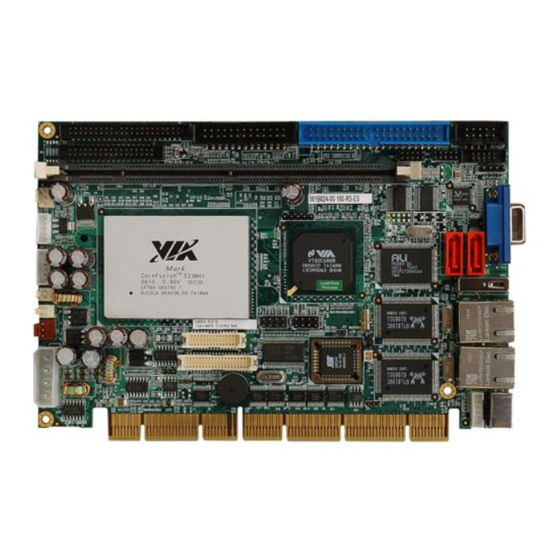
IEI Technology PCISA-6612 User Manual (220 pages)
PCISA CPU Card with Intel Pentium M/Celeron M400/533Mhz FSB processor CRT/LCD, Dual PCI-E Gbe USB 2.0. SATA and Audio
Brand:
IEI Technology
| Category:
Computer Hardware
| Size: 9 MB
Table of Contents
Table of Contents
3
1 Introduction
15
Pcisa-6612 Cpu Card Overview
16
PCISA-6612 Models
16
PCISA-6612 Applications
16
Table 1-1: PCISA-6612 Model Specifications
16
PCISA-6612 Benefits
17
PCISA-6612 Features
17
Pcisa-6612 Overview
18
Figure 1-1: PCISA-6612 Overview
18
Figure 1-2: PCISA-6612 Solder Side Overview
19
PCISA-6612 Connectors
19
Technical Specifications
21
Table 1-2: Technical Specifications
22
2 Detailed Specifications
23
Overview
24
Compatible Iei Backplanes
24
Board Dimensions
24
Cpu Support
24
Intel ® Pentium ® M
24
Intel ® Celeron ® M
24
Table 2-1: Supported Cpus
24
Table 2-2: Supported Intel ® Pentium ® M Cpus
25
On-Board Chipsets
26
Northbridge and Southbridge Chipsets
26
Sis661Cx Northbridge Chipset
26
Table 2-3: Supported Intel ® Celeron ® M Cpus
26
Sis966 Southbridge Chipset
27
Data Flow
28
Figure 2-1: Data Flow Block Diagram
28
Graphics Support
29
Memory Support
30
Pci Bus Interface Support
30
Gbe Ethernet
30
Super I/O
31
Drive Interfaces
34
SATA Drives
34
IDE HDD Interfaces
34
Floppy Disk Drive (FDD)
34
Serial Ports
34
Audio Codec
35
Audio Codec Overview
35
Audo Codec Features
35
Real Time Clock
36
System Monitoring
36
Bios
36
Operating Temperature and Temperature Control
37
Power Consumption
37
Packaged Contents and Optional Accessory Items
37
Package Contents
37
Table 2-4: Power Consumption
37
Optional Accessory Items
38
3 Connectors and Jumpers
39
Peripheral Interface Connectors
40
PCISA-6612 Layout
40
Figure 3-1: Connector and Jumper Locations
40
Peripheral Interface Connectors
41
External Peripheral Interface Connectors
42
Table 3-1: Peripheral Interface Connectors
42
Table 3-2: External Peripheral Interface Connectors
42
On-Board Jumpers
43
Internal Peripheral Connectors
43
Audio Connector (8-Pin)
43
Table 3-3: On-Board Jumpers
43
Backplane to Mainboard Connector
44
Figure 3-2: Audio Connector Location
44
Table 3-4: Audio Connector Pinouts
44
Compactflash ® Connector
45
Figure 3-3: Backplane to Mainboard Connector Location
45
Table 3-5: Backplane to Mainboard Connector Pinouts
45
Figure 3-4: Compactflash ® Connector Location
46
Table 3-6: Compactflash ® Connector Pinouts
47
CPU Fan Connector (+5V)
48
Figure 3-5: CPU Fan Connector Location
48
Digital Input/Output (DIO) Connector
49
Figure 3-6: DIO Connector Connector Locations
49
Table 3-7: CPU Fan Connector Pinouts
49
Floppy Disk Connector
50
Figure 3-7: 34-Pin FDD Connector Location
50
Table 3-8: DIO Connector Connector Pinouts
50
Front Panel Connector
51
Table 3-9: 34-Pin FDD Connector Pinouts
51
IDE Connector
52
Figure 3-8: Front Panel Connector Locations
52
Table 3-10: Front Panel Connector Pinouts
52
Figure 3-9: IDE Device Connector Location
53
IR Interface Connector
54
Table 3-11: Primary IDE Connector Pinouts
54
Keyboard Connector
55
Figure 3-10: IR Interface Connector Location
55
Table 3-12: IR Interface Connector Pinouts
55
LCD Inverter Connector
56
Figure 3-11: Keyboard Connector Location
56
Table 3-13: Keyboard/Mouse Connector Pinouts
56
LCD LVDS Interface Connector
57
Figure 3-12: LCD Inverter Connector Pinout Location
57
Table 3-14: LCD Inverter Connector Pinouts
57
Figure 3-13: TFT LCD LVDS Connector Location
58
Parallel Port Connector
59
Table 3-15: TFT LCD LVDS Connector Pinouts
59
Figure 3-14: Parallel Port Connector Location
60
Table 3-16: Parallel Port Connector Pinouts
60
Serial Port Connectors
61
Figure 3-15: RS-232 Serial Port Connectors Locations
61
SATA Drive Connectors
62
Table 3-17: RS-232 Serial Port Connectors Pinouts
62
Figure 3-16: SATA Drive Connector Locations
63
Table 3-18: SATA Drive Connector Pinouts
63
USB Connectors
64
Figure 3-17: USB Connectors Location
64
Table 3-19: USB Port Connectors Pinouts
64
External Peripheral Interface Connector Panel
65
Figure 3-18: PCISA-6612 External Peripheral Interface Connector Panel
65
Figure 3-19: RJ-45 Ethernet Connector
66
LAN Connectors
66
Table 3-20: LAN Pinouts
66
Figure 3-20: Mini-DIN 6 PS/2 Connector
67
Mini-DIN 6 PS/2 Connector
67
Table 3-21: RJ-45 Ethernet Connector Leds
67
Table 3-22: Mini-DIN 6 PS/2 Connector
68
Table 3-23: USB Port Pinouts
68
USB Connector
68
Figure 3-21: VGA Connector
69
Table 3-24: VGA Connector Pinouts
69
VGA Connector
69
4 Installation
71
Anti-Static Precautions
72
Installation Considerations
72
Installation Notices
72
Unpacking
73
Unpacking Precautions
73
Checklist
74
Pcisa-6612 Cpu Card Installation
74
Preinstalled Component
75
Components to Install
75
DIMM Module Installation
75
Figure 4-1: DIMM Module Installation
76
Peripheral Device Connection
77
Table 4-1: IEI Provided Cables
77
Figure 4-2: Connection of IDE Connector
78
Figure 4-3: SATA Drive Cable Connection
79
Figure 4-4: SATA Drive Connection
80
Figure 4-5: Compactflash ® Card Installation
81
Figure 4-6: Dual RS-232 Cable Installation
82
Jumper Settings
83
Figure 4-7: USB Cable Installation
83
Clear CMOS Jumper
85
Figure 4-8: Jumper Locations
85
LVDS Voltage Selection
86
Table 4-2: Clear CMOS Jumper Settings
86
Table 4-3: LVDS Voltage Selection Jumper Settings
87
Table 4-4: VCCA Voltage Selection Jumper Settings
87
VCCA Voltage Selection
87
Inserting the Cpu Card
88
Rear Panel Connectors
88
Keyboard and Mouse Connection
88
Gigabit Ethernet Connection
88
USB Connection
88
VGA Port Installation
89
5 Bios Settings
91
Introduction
92
Starting Setup
92
Using Setup
92
Getting Help
93
Unable to Reboot after Configuration Changes
93
BIOS Menu Bar
93
Table 5-1: BIOS Navigation Keys
93
Main
94
Advanced
95
CPU Configuration
96
BIOS Menu 3: CPU Configuration
97
IDE Configuration
99
BIOS Menu 5: IDE Master and IDE Slave Configuration
103
Floppy Configuration
107
Super IO Configuration
108
Hardware Health Configuration
112
ACPI Configuration
113
BIOS Menu 10: Advanced ACPI Configuration
115
MPS Configuration
117
USB Configuration
118
Menu 13: USB Mass Storage Device Configuration
121
Pci/Pnp
123
BIOS Menu 14: Pci/Pnp Configuration
125
Boot
130
Boot Settings Configuration
131
Boot Device Priority
134
Hard Disk Drives
135
BIOS Menu 18: Hard Disk Drives
136
Removable Drives
137
CD/DVD Drives
138
BIOS Menu 20: CD/DVD Drives
139
Security
140
Chipset
141
Northbridge SIS661FX Configuration
142
BIOS Menu 23:Northbridge Chipset Configuration
143
Southbridge Sis966 Configuration
145
Power Management
147
Exit
149
6 Driver Installation
151
Available Software Drivers
152
Sis AGP Driver Installation
153
Figure 6-1: SIS Solution CD Main Menu
153
Figure 6-2: Starting Install Shield Wizard Screen
154
Figure 6-3: Preparing Setup Screen
154
Figure 6-4: Install Shield Screen
155
Figure 6-5: Installing Screen
155
Vga Driver Installation
156
Figure 6-6: Restart the Computer
156
Figure 6-7: CD VGA Folder
157
Figure 6-8: CD Vga\3.76Logo Folder
157
Figure 6-9: Starting Installshield Wizard Screen
158
Figure 6-10: Preparing Setup Screen
158
Figure 6-11: VGA Utilities Welcome Screen
159
Figure 6-12: Select Setup Installation Type
160
Figure 6-13: Select Folders to Copy Files
161
Figure 6-14: Review Settings
162
Figure 6-15: Read Readme File
163
Audio Driver Installation
164
Figure 6-16: Restart the Computer
164
Figure 6-17: CD 4-Audio\Ac97\Windows Folder
165
Figure 6-18: Audio Driver Install Shield Wizard Starting
165
Figure 6-19: Audio Driver Setup Preparation
166
Figure 6-20: Audio Driver Welcome Screen
167
Figure 6-21: Audio Driver Software Configuration
168
Figure 6-22: Audio Driver Digital Signal
169
Figure 6-23: Audio Driver Installation Begins
170
Figure 6-24: Audio Driver Installation Complete
171
Lan Driver Installation
172
Figure 6-25: Access Windows Control Panel
172
Figure 6-26: Double Click the System Icon
173
Figure 6-27: Double Click the Device Manager Tab
173
Figure 6-28: Device Manager List
174
Figure 6-29: Search for Suitable Driver
175
Figure 6-30: Locate Driver Files
176
Sis IDE Driver Installation
177
Figure 6-31: Location Browsing Window
177
Figure 6-32: Select a Language
178
Figure 6-33: Welcome Screen
178
Figure 6-34: Select Components
179
Figure 6-35: Chipset Driver Installation
179
Sis SATA RAID Utility Installation
180
Figure 6-36: CD 6-SATA Raid\Windows Folder
180
Figure 6-37: Starting Install Shield Wizard
181
Figure 6-38: Preparing Setup
181
Figure 6-39: Install Shield
182
Figure 6-40: License Agreement
183
Figure 6-41: Install Application Directory
184
Figure 6-42: Select Needed Components
185
Figure 6-43: Ready to Install
186
Figure 6-44: Setup Status
187
Figure 6-45: Restart the Computer
188
Index
217
Advertisement
Advertisement
Related Products
IEI Technology PCISA-PV-D5251T
IEI Technology PCISA-PV-D4251T
IEI Technology PCISA-PV-D4251
IEI Technology PCISA-PV-N4551T
IEI Technology PCISA-PV-D5251
IEI Technology PCISA-BT
IEI Technology PCISA-BT-E38251
IEI Technology PCISA-PV-N4551-R10
IEI Technology PCISA-PV-D5251-R10
IEI Technology PCISA-9652-R10
IEI Technology Categories
Motherboard
Touch Panel
Computer Hardware
Single board computers
Desktop
More IEI Technology Manuals
Login
Sign In
OR
Sign in with Facebook
Sign in with Google
Upload manual
Upload from disk
Upload from URL