Table of Contents
Advertisement
Quick Links
Advertisement
Table of Contents

Related Manuals for Panduit Atlona Omega AT-OME-RX31


Summary of Contents for Panduit Atlona Omega AT-OME-RX31
- Page 1 4K / UHD Scaler for HDMI and HDBaseT ™ Atlona Manuals AT-OME-RX31 Switchers...
- Page 2 Version Information Version Release Date Notes Mar 2020 Initial release AT-OME-RX31...
- Page 3 Welcome to Atlona! Thank you for purchasing this Atlona product. We hope you enjoy it and will take a extra few moments to register your new purchase. Registration only takes a few minutes and protects this product against theft or loss. In addition, you will receive notifications of product updates and firmware.
- Page 4 Atlona, Inc. (“Atlona”) Limited Product Warranty Coverage Atlona warrants its products will substantially perform to their published specifications and will be free from defects in materials and workmanship under normal use, conditions and service. Under its Limited Product Warranty, Atlona, at its sole discretion, will either: •...
- Page 5 Atlona, Inc. (“Atlona”) Limited Product Warranty • Damage, deterioration or malfunction resulting from the installation or removal of this product from any installation, any unauthorized tampering with this product, any repairs attempted by anyone unauthorized by Atlona to make such repairs, or any other cause which does not relate directly to a defect in materials and/or workmanship of this product.
- Page 6 Important Safety Information 9. Do not defeat the safety purpose of a polarized CAUTION or grounding-type plug. A polarized plug has two RISK OF ELECTRIC SHOCK blades with one wider than the other. A grounding DO NOT OPEN type plug has two blades and a third grounding CAUTION: TO REDUCT THE RISK OF prong.
-
Page 7: Table Of Contents
Table of Contents Introduction Features Package Contents Panel Description Installation Captive Screw Connections Mounting Instructions Connection Instructions IP Modes Connection Diagram WebGUI Video Settings Audio Display RS-232 EDID Time Config System HDBT Appendix Specifications AT-OME-RX31... -
Page 8: Introduction
Introduction The Atlona AT-OME-RX31 is an HDBaseT receiver, three-input switcher, and 4K/UHD scaler with a local HDMI input. Part of the Omega™ Series of integration products for modern AV communications and collaboration, the OME-RX31 features two HDBaseT inputs for receiving video up to 4K/60 4:2:0, plus embedded audio, control, and Ethernet over distances up to 330 feet (100 meters). -
Page 9: Panel Description
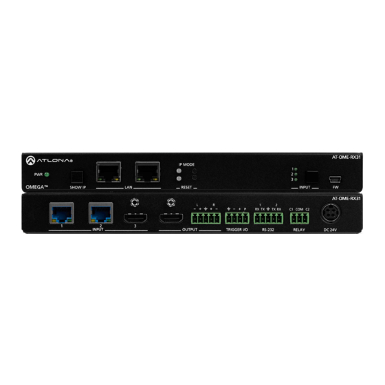
Panel Description AT-OME-RX31 IP MODE OMEGA SHOW IP RESET INPUT AT-OME-RX31 TX RX COM C2 INPUT OUTPUT TRIGGER I/O RS-232 RELAY DC 24V PWR LED HDMI IN Illuminates green when receiving power. Connect an HDMI cable from an HDMI source to this port. -
Page 10: Installation
Installation Captive Screw Connections RS-232 A 5-pin captive screw connector has been included for RS-232. The ground pin is shared between port 1 and port 2. NOTE: Port 1 will control the display and port 2 is for unit control. Pin out will be determined by the RS-232 cable and connect as RX (receive), TX (transmit) and... - Page 11 Installation Trigger I/O The TRIGGER I/O port allows voltage-controlled devices, such as an occupancy sensor, to be connected to the AT- OME-RX31. Use the included 4-pin captive screw connector to connect the device. Voltage range is 3 to 30 V DC. GND - There are 4 connections for the trigger: GND, -, +, and P (Ground, Negative, Positive, and Power).
-
Page 12: Mounting Instructions
Installation Mounting Instructions The AT-OME-RX31 includes two mounting brackets and four mounting screws, which can be used to attach the units to any flat surface. 1. Remove the top 2 case screws on the side of the unit. 2. Align the mounting brackets to the side of the units. 3. -
Page 13: Connection Instructions
Installation Cable Recommendation Guidelines Refer to the tables below for recommended cabling when using Altona products with HDBaseT. The green bars indicate the signal quality when using each type of cable. Higher-quality signals are represented by more bars. CAT5e CAT6 CAT6a CAT7 Core... -
Page 14: Ip Modes
Installation IP Modes DHCP By default, the AT-OME-RX31 is set to DHCP mode. In this mode, when the AT-OME-RX31 is connected to the Local Area Network (LAN), it will automatically be assigned an IP address by the DHCP server (if available). Press the DEVICE IP button to show the IP address in the top left corner of the display. -
Page 15: Webgui
WebGUI The AT-OME-RX31 includes a built-in webGUI, which allows easy remote management and control of all features. Follow the instructions below to access the webGUI. 1. Make sure that an Ethernet cable is connected between the LAN port on the AT-OME-RX31 and the network. 2. -
Page 16: Video Settings
webGUI Video Settings Select Video from the top navigation to adjust routing and video settings. HDCP Settings On - Sets the HDCP of the HDMI or HDBaseT ports to auto, allowing HDCP to switch between compliant and non-compliant according to the source and display HDCP handshake status. Off - Sets the HDBaseT or HDMI port to HDCP non-compliant. - Page 17 webGUI Output Input Selection - Use the drop down menu to switch between A/V Mute (no signal), HDMI, HDBaseT 1, HDBaseT 2, Internal Pattern 1, Internal Pattern 2, and Internal Pattern 3 source signals. Scaler - When enabled, will display extra options. Output Resolution - Select the output resolution the source signal will be scaled to from the drop down menu.
-
Page 18: Audio
webGUI Audio Select Audio from the top navigation to adjust volume, mute status, and EQ levels. Output Audio HDMI / L/R Enable - Unmutes the audio output signal, allowing audio to pass through the outputs. HDMI / L/R Disable - Mutes the audio output signal of the ports. No audio will pass when selected. NOTE: HDMI muting will mute the audio embedded on the HDMI output and L/R muting will mute the audio on the analog audio output. -
Page 19: Display
webGUI Display Select Display from the top navigation to adjust display control settings. Command: Power - Press to send the CEC power on or off command out through the HDMI port. Command: Volume - Press to send the CEC Volume up, down, or mute commands through the HDMI port. System Settings Display Auto Power - Set this toggle to ENABLED to allow the AT-OME-RX31 to send the power-on command to the display when an A/V signal is detected. - Page 20 webGUI TCP/IP Settings of Controlled Device (only available when IP is selected) IP Mode - Toggle telnet login mode between Non-Login and Login. If set to Login, a username and password will be required to control the controlled device via TCP/IP. IP Address - Sets to the IP of the controlled device/display.
- Page 21 webGUI RS-232 Select RS-232 from the top navigation to adjust the zone control parameters for the RS-232 port. RS-232 Parameter Setting RX RS232 1 (Display) - These port settings are for controlling the display. Defaults are 9600, 8, None, and 1. RX RS232 2 (Console) - These port settings are for local control by a third-party control system.
-
Page 22: Edid
webGUI EDID Select EDID from the top navigation to save/load EDIDs. EDID EDID Settings - Use the drop down menu to select from default (highest common resolution between source and display), 4 internal EDIDs, and 1 previously saved EDID. EDID Saved - The ID field will display the memory # and currently saved EDID name, select output 1 from the drop down menu. -
Page 23: Time
webGUI Time Select Time from the top navigation to select the time server for the unit to sync to. SNTP Configuration Server info - Select the time zone the unit will run in. If the unit has internet access, it can be set to sync to a server as well. -
Page 24: Config
webGUI Config Select Config from the top navigation to update the admin password. Users Admin Password - Update the admin password for the switcher. Only the admin password may be changed, the username will remain admin. NOTE: The passwords cannot contain any special characters. e.g. !@#$%/^&*\?+-;’”. Once the new password has been entered, press the Save button to make the password live. -
Page 25: System
webGUI System Select System from the top navigation to adjust relay, network, or system options. Relay Control - Set the relay to either follow the display’s status or be manually set using the selectors in the WebGUI. When the unit is set to pulse, the relay will latch for the designated pulse time before opening again. The relay that opens and closes will be determined by the power state: Power On Relay 1: Latch will close for designated pulse time then open. - Page 26 webGUI Network MAC Address - Displays the MAC address of the unit. IP Mode - Switch between static and DHCP IP modes. IP, Netmask, Gateway - This will display the unit’s current DHCP IP settings. When set to static, fill in the IP address, netmask, and gateway.
-
Page 27: Hdbt
webGUI HDBT Select HDBT to open the HDBaseT cable test page. This page will check extender versions, cable status and length, and Video Quality. HDBT Test HDBaseT Zone - Use the drop down menu to select which HDBaseT input is being tested. Only active connections can be tested. -
Page 28: Appendix
Appendix Specifications Video HDMI HDCP UHD/HD 4096×2160 @ 60 /50/30/25/24 Hz 720x576p @ 50 Hz 3840×2160 @ 60 /50/30/25/24 Hz 720x576i @ 50 Hz 1920x1080p @ 60/59.94/50/30/29.97/25/24/23.98 Hz 640x480p @ 60/59.96 Hz 1920x1080i @ 30/29.97/25 Hz 640x480i @ 30 Hz 1280x720p @ 60/59.94/50 Hz VESA 2560×1600... - Page 29 Appendix Resolution / Distance 4K/UHD - Feet / Meters 1080p - Feet / Meters HDMI IN/OUT CAT5e CAT6/6a/7 Connectors, Controls, and Indicators HDMI IN 1 – Type A, 19-pin female HDMI OUT 1 – Type A, 19-pin female AUDIO OUT 1 –...
- Page 30 Toll free US International atlona.com 877.536.3976 41.43.508.4321 • • © 2020 Atlona Inc. All rights reserved. “Atlona” and the Atlona logo are registered trademarks of Atlona Inc. All other brand names and trademarks or registered trademarks are the property of their respective owners. Pricing, specifications and availability subject to change without notice.
Need help?
Do you have a question about the Atlona Omega AT-OME-RX31 and is the answer not in the manual?
Questions and answers