Norac UC4+ Roll Control Installation Manual
Spray height controller, hardi autoheight, hardi dah or dah09
Hide thumbs
Also See for UC4+ Roll Control:
- Installation manual (32 pages) ,
- Installation manual (33 pages)

Subscribe to Our Youtube Channel
Related Manuals for Norac UC4+ Roll Control


Summary of Contents for Norac UC4+ Roll Control
- Page 1 Spray Height Controller HARDI AutoHeight HARDI DAH or DAH09 Installation Manual Improving the competitiveness of Industry and Agriculture through Precision Measurement...
- Page 2 NOTICE NORAC Systems International Inc. reserves the right to improve products and their specifications without notice and without the requirement to update products sold previously. Every effort has been made to ensure the accuracy of the information contained in this manual. The technical...
-
Page 3: Table Of Contents
HARDI DAH ............39 ABLE NTERFACE C12: 44658 -78 – C UC4 BC I HARDI DAH 09 ............40 ABLE NTERFACE NORAC VALVE BLOCK STENCIL (ONLY FOR LPZ BOOM INSTALLS) ..........41 44963D ................................. 41 ... -
Page 4: Introduction
INTRODUCTION Congratulations on your purchase of the NORAC UC4+ Spray Height Controller. This system is manufactured with top quality components and is engineered using the latest technology to provide operating features and reliability unmatched for years to come. When properly used the system can provide protection from sprayer boom damage, improve sprayer efficiency, and ensure chemicals are applied correctly. - Page 5 GENERAL SYSTEM DESCRIPTION Figure 1 depicts the general system layout of the UC4+ Spray Height Control system. Figure 1 – System Components and General Location (COMMANDER and NAVIGATOR)
-
Page 6: General System Description
However, NORAC cannot boom movement will need to be done guarantee all parts fit as intended due to the first. Once the hydraulics have been variations of the sprayer by the manufacturer. -
Page 7: Parts Lists
PARTS LISTS The parts that come with your UC4+ Sprayer Boom System are listed in Table 1. The item number on the left side of this table references each part. 3.1 UC4+ P ARTS Please ensure that all parts in your kit are present before proceeding with your installation. Table 1 –... - Page 8 FACE P - PIPE The use of dielectric grease is not recommended on any NORAC electrical connections. To ensure all stainless steel hardware does not gall or seize apply a light coating of the supplied Permatex Anti-seize grease to all threaded parts upon installation. Permatex...
-
Page 9: Hardi Parts Lists
3.2 HARDI P ARTS ISTS The required HARDI Parts necessary for the UC4+ install are listed in Table 3. Table 3 – HARDI Parts Item Part Number Name Quantity HARDI01 232109 1/4" BSP FITTING HARDI02 784030 4FBSP-4FBSP HYD HOSE (350MM LENGTH) HARDI03 784022 4FBSP-4FBSP HYD HOSE (650MM LENGTH) - Page 10 The parts that come with your UC4+ System are shown below in their general installation configuration. Cables C12A and C13 may be used in place of Cable C12 in some installations. See Section 4.10 for details. Figure 3 – UC4+ Spray Height Control Components...
- Page 11 Figure 4 – Hydraulic Plumbing Schematic...
-
Page 12: Installation Procedure
INSTALLATION PROCEDURE 4.1 F UNCTIONALITY CHECK Before beginning the install, ensure all hydraulic boom functions are operating properly on the sprayer. o All Fold Functions o Main Lift Function o Wing Tilt Functions o Slant Function Figure 5 –Boom Push Test- Critically Damped 4.2 E XISTING SYSTEM CHECK... -
Page 13: Wing Sensor Installation
(M01) Bracket Assembly implications. To assemble the breakaway sensor bracket: 4. Mount the NORAC UC4+ ultrasonic sensor (E02) into the sensor brackets. The sensors a) Assemble the bolt and nut into the should be oriented forward (ahead) of the collar. - Page 14 side proceeding to the largest General mounting rules for UC4+ serial number on the right hand ultrasonic wing sensors: side (Figure 14). a) In its lowest position, the sensor mouth 5. Sensor cables should run through the must be 9 inches or more from the ground. mounting bracket tube and then behind the b) The bottom of the sensor must be at least 9 member the bracket is mounted onto.
-
Page 15: Suggested Mounting For The Wing Bracket On Hpz(24-36M) /Haz (18-30M)
4.3.1 Suggested mounting for the wing bracket on HPZ(24-36m) /HAZ (18- 30m) Below is the suggested mounting location for the UC4 brackets on the HPZ (24-36m) or HAZ (18-30m) booms. Mounting location is just inside of the boom break-away section (A). Figure 11 - Suggested UC4 Bracket Mounting Location (viewed from front) on 24m HAZ IMPORTANT: Avoid mounting the bracket too close to the touch-down wheel (B). -
Page 16: Suggested Mounting For The Wing Bracket On Haz (32-36M) Boom
4.3.2 Suggested mounting for the wing bracket on HAZ (32-36m) boom Below is the suggested mounting location for the UC4 brackets on the HAZ 32-36m booms. Mounting location is just inside of the boom break-away section (A). Figure 12 - Suggested UC4 Bracket Mounting Location (viewed from front) on 36m HAZ... -
Page 17: Suggested Mounting For The Wing Bracket On Lpz
4.3.3 Suggested mounting for the wing bracket on LPZ Below is the suggested mounting location for the UC4 brackets on the LPZ boom. Mounting location is just inside of the boom break-away section (A). Figure 13 - Suggested UC4 Bracket Mounting Location on LPZ boom... - Page 18 When arranging height sensors, install the serial numbers from lowest to highest, left to right. Apply a light coating of the supplied Permatex Anti-seize grease to all threaded parts upon installation. Figure 14 – Sensor Serial Number Installation Location (example)
-
Page 19: Main Lift Sensor Installation
4.4 M AIN LIFT SENSOR INSTALLATION The General Mounting Rules for UC4+ Ultrasonic Sensors (Section 4.3), must also be followed for the Main Lift sensor. 4.4.1 FORCE / TWIN FORCE (HPZ/ HAZ) 1. Mount the main lift bracket (B11) as illustrated in Figure 15. -
Page 20: Delta (Lpz)
4.4.2 DELTA (LPZ) No mounting bracket is required. Mount the main lift sensor as illustrated in Figure 16. Ensure sensor cable is securely fastened with cable ties. Figure 16 - Main Lift Sensor Mounting on LPZ Center-Part... -
Page 21: Roll Sensor Installation
4.5 R OLL SENSOR INSTALLATION Ensure roll sensor assemblies are Mount the roll sensors to the included roll oriented as shown in Figure 18 with sensor brackets using the machine screws and the cable exiting towards the right- nylon lock nuts, as illustrated in Figure 17. hand wing. -
Page 22: Force / Twin Force (Hpz/ Haz)
4.5.1 FORCE / TWIN FORCE (HPZ/ HAZ) Mount the Boom Roll Sensor (E04) to the Item E03 (has temperature probe) is boom center section, as illustrated below. attached to the non-rotating part of the Ensure the circular connector is pointing boom. -
Page 23: Delta (Lpz)
4.5.2 DELTA (LPZ) Mount the Boom Roll Sensor (E04) to the Item E03 (has temperature probe) is boom center section, as illustrated below. attached to the non-rotating part of the Ensure the circular connector is pointing boom. towards the right hand wing (when looking from ... -
Page 24: Temperature Probe
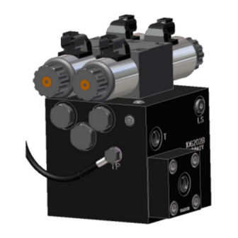
4.6 T EMPERATURE ROBE Once the block is mounted, fasten the temperature probe (E03) to the UC4 valve block using the included 3/8x1/2” bolt as illustrated in Figure 21. Figure 21 - UC4+ Valve Block with Temperature Probe Installed... -
Page 25: Hydraulic Installation
1. Refer to Figure 22. On a clean surface remove the plastic plugs from the “A”, “B”, “P”, and “T” ports of the NORAC hydraulic valve (V01). Install the 6MB-4MBSPP fittings (F02) on the “P” and “T” ports and tighten to 18 ft-lbs. -
Page 26: Hardi Valve Mounting
4.8 HARDI VALVE MOUNTING 4.8.1 FORCE/TWIN FORCE (HPZ / HAZ) Mount the Valve block using the mounting plate hardware illustrated. Suggested mounting location on the HPZ / HAZ center- part is shown in Figure 24. Figure 24 - Valve Mounting on HPZ / HAZ... -
Page 27: Delta (Lpz)
4.8.2 DELTA (LPZ) Mount the block as illustrated in Figure 26. This will require drilling holes though the sheet- metal on the boom. Use Item B14 and B15 (do not use Item B10 mounting hardware). Figure 25 – Valve Block Mounting Location on LPZ Figure 26 –... - Page 28 X = 82.5mm (3.25 in) the LPZ boom. Drill holes large enough to accommodate 3/8” bolts. See Section 7 for a drilling stencil. Figure 27 – NORAC Valve Block Mounting Hole Dimensions...
-
Page 29: Hydraulic Plumbing
HARDI02 between the “B” ports and the tee fittings installed in the HARDI block. c. The “A” ports on the NORAC block are plugged. The “lower” lines of the cylinders are to remain attached to the... -
Page 30: Electrical Installation
(DAH or DAH09), either (Bottom of switch pressed IN). Use the NORAC part 44658-51 or 44658-78 caution when handling the 12 V power will be required for this installation. line of the sprayer wiring. -
Page 31: General Installation Instructions Using The 44658-51
4.10.1 General Installation instructions using the 44658-51 Figure 29 – Cable Routing Overview (Using 44658-51) 1. Connect the UC4 power cable (C10) to the the boom to avoid damage to the cable UC4+ Control Panel in the cab. Ensure that during field operation or boom folding. - Page 32 PCB of C12A. Screw it down to the hydraulics, the boom slant will not socket. function. 8. Connect the NORAC C12A between the J4 connection on the HARDI PCB and the blue wiring harness. a) Remove the blue harness from J4 (37-pin DB male socket) on the PCB inside of the Job-com.
- Page 33 9. Run the free end of C12A through an unused hole of the electronics enclosure. This requires installing Liquidtight connector (Pt. HARDI04, HARDI05) BEFORE proceeding to step 8. 10. Put pins of C12A to the 6-pin and 4-pin Weatherpack connectors (S6 and S4) which are included in this kit according to the table below.
-
Page 34: General Installation Instructions Using The 44658-78
4.10.2 General Installation Instructions using the 44658-78 Ensure sprayer power is turned off. Figure 33 – Cable Routing Overview (Using 44658-78) 1. Connect the UC4 power cable (C10) to the cable C02 to cable C02A. Connect cable UC4+ Control Panel in the cab. Ensure that C02A to cable C11. - Page 35 12 VDC and GND DB15 DIP switches Figure 34 - DAH09 PCB for AutoHeight 11. Configure the system for Autoslant by b) If the sprayer uses a DAH valve block set setting the DIP switches on DAH09 board: DIP switch 1 to OFF. If the sprayer uses a DH valve block set DIP switch 1 to a) Set DIP switches 2,3,4,6 and 8 to ON.
- Page 36 Notice: Additional instructions are available in the UC4+BC+HD4-INSTE (End-user manual) for configuring spray ON/OFF signal sensing and headland modes. With these features the Autoslant system will function together with the spray signal, switching boom height control on and off with the spray signal. This function can also configured raise...
-
Page 37: Norac Valve And Sensor Connections
C11 (Figure 29). End-User document. 3. Install the 2-pin connectors from C03 onto each NORAC valve as shown in Figure 38. 4. The connectors on the valve cable (C03) are marked RIGHT UP, LEFT UP, RIGHT DOWN and LEFT DOWN. -
Page 38: Completing The Factory Installation
1. Test the functionality of the original manufacturer’s boom controls. Power to a. Complete Install- this will setup the the NORAC control panel does not need to entire Autoheight system, requiring fully on be for the sprayer controls to function. range of boom moment. Hydraulics will... -
Page 39: Electrical Reference - Cable Drawings
ELECTRICAL REFERENCE – CABLE DRAWINGS 6.1 I C02: 44668 – S ENSOR RANCH ABLE 6.2 I C02B: 44664 – C UC4 CAN N ABLE... -
Page 40: Item C3: 44656D - Cable Valve Variable Rate Dt
6.3 I C3: 44656D – C ABLE ALVE ARIABLE... -
Page 41: Item C10: 44658 -52 - Cable Uc4 Bc Power C10 Hardi
6.4 I C10: 44658 -52 – C UC4 BC P C10 HARDI ABLE OWER... -
Page 42: Item C11: 44658 -50 - Cable Uc4 Bc Extension C11 Hardi
6.5 I C11: 44658 -50 – C UC4 BC C11 HARDI ABLE EXTENSION... -
Page 43: Item C12A: 44658 -51 - Cable Uc4 Bc Interface Hardi Dah
6.6 I C12A: 44658 -51 – C UC4 BC I HARDI DAH ABLE NTERFACE... -
Page 44: Item C12: 44658 -78 - Cable Uc4 Bc Interface Hardi Dah 09
6.7 I C12: 44658 -78 – C UC4 BC I HARDI DAH 09 ABLE NTERFACE... -
Page 45: Norac Valve Block Stencil (Only For Lpz Boom Installs)
NORAC VALVE BLOCK STENCIL (ONLY FOR LPZ BOOM INSTALLS) 7.1 44963D ENSURE TRUE DIMENSIONS MATCH AS LABELLED BELOW... - Page 46 Canada NORAC Systems International Inc. CALL TOLL FREE: 1-800-667-3921 (306)664-6711 SHIPPING ADDRESS: 3702 Kinnear Place Saskatoon, SK S7P 0A6 United States NORAC, Inc. CALL TOLL FREE: 1-866-306-6722 (952)224-4142 SHIPPING ADDRESS: 6667 West Old Shakopee Road, Suite 111 Bloomington, MN...
Need help?
Do you have a question about the UC4+ Roll Control and is the answer not in the manual?
Questions and answers