Norac UC4 Installation Manual
Total control automatic boom height system
Hide thumbs
Also See for UC4:
- Operator's manual (60 pages) ,
- Installation manual (46 pages) ,
- Quick manual (40 pages)
Table of Contents
Advertisement
Quick Links
Automatic Boom Height
NITRO
Canada
NORAC Systems International Inc.
CALL TOLL FREE: 1-800-667-3921
(306) 664-6711
SHIPPING ADDRESS:
3702 Kinnear Place
Saskatoon, SK
S7P 0A6
For other service locations please view our website:
Improving the Competitiveness of Industry and Agriculture
UC
Total Control
System
(Miller 200 Series 1999+, 120-ft Boom)
Installation Manual
www.norac.ca
through Precision Measurement
4
United States
NORAC, Inc.
CALL TOLL FREE: 1-866-306-6722
(763) 786-3080
SHIPPING ADDRESS:
1290 Osborne Rd. NE, Suite F
Fridley, MN
55432-2892
Advertisement
Table of Contents

Related Manuals for Norac UC4


Summary of Contents for Norac UC4
- Page 1 Total Control Automatic Boom Height System NITRO (Miller 200 Series 1999+, 120-ft Boom) Installation Manual Canada United States NORAC Systems International Inc. NORAC, Inc. CALL TOLL FREE: 1-800-667-3921 CALL TOLL FREE: 1-866-306-6722 (306) 664-6711 (763) 786-3080 SHIPPING ADDRESS: SHIPPING ADDRESS: 3702 Kinnear Place 1290 Osborne Rd.
- Page 2 Reorder P/N: UC4-BC-NT2-INST Rev D (Nitro) NOTICE NORAC Systems International Inc. reserves the right to improve products and their specifications without notice and without the requirement to update products sold previously. Every effort has been made to ensure the accuracy of the information...
-
Page 3: Table Of Contents
TABLE OF CONTENTS INTRODUCTION ..........................2 GENERAL SYSTEM DESCRIPTION ....................3 PARTS LIST............................4 INSTALLATION PROCEDURE ......................9 4.1 E ................9 XISTING YDRAULIC YSTEM UNCTION HECK 4.2 B .......................... 10 PEED 4.3 W ......................12 ENSOR NSTALLATION 4.4 M .................... -
Page 4: Introduction
1 INTRODUCTION Congratulations on your purchase of the Norac UC4 automated sprayer boom height control system. This system is manufactured with top quality components and is engineered using the latest technology to provide operating features and reliability unmatched for years to come. -
Page 5: General System Description
ATTENTION: When installing the UC4 system please be aware that at a point in the installation your sprayer booms will be inoperative until the installation is complete. Any installation procedure requiring boom movement will need to be done first. -
Page 6: Parts List
3 PARTS LIST The parts that come with your UC4 Sprayer Boom System are listed in Table 1. In this document, the item number shown on the left side of this table references each part. Please ensure that all parts in your kit are present before proceeding with your installation. - Page 7 COUPLING HYD 6FJCN CAP NO 6 FEMALE JIC 44928 ORIFICE INSERT .047 IN ONE WAY 103312 COUPLING HYD 6MB 6MJ * MISC. PARTS * 446BC-MAN-1 MANUAL UC4 BOOM CONTROL TECHNICAL LARGE BOOKLET 446BC-MAN-2 MANUAL UC4 BOOM CONTROL QUICK REFERENCE SMALL BOOKLET 100084 TIE CABLE 21 IN BLACK 100091 TIE CABLE 7.5 IN BLACK...
- Page 8 100870 NUT LOCK NYLON NC PLTD 5/16 IN If the part number for Item V1 (NORAC valve block) is 44933S, Items H17 are not included in the kit. The #44933S valve block has solenoid valves whose engraved part number is...
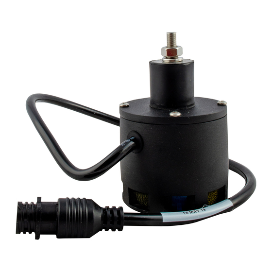
- Page 9 The parts that come with your UC4 System are shown below in their general installation configuration. Figure 2 – UC4 Boom Control Components...
- Page 10 Figure 3 – Hydraulic Plumbing Schematic (Single-Acting Hydraulics)
-
Page 11: Installation Procedure
4 INSTALLATION PROCEDURE Before installing the NORAC UC4 Boom Control System to your sprayer, it is necessary to check that all functions of the existing hydraulic system are working properly. Furthermore, it is informative to determine how quickly your sprayer booms and main (center) section are able to change their position without the UC4 System installed. -
Page 12: Boom Speed Test
4.2 B PEED IMPORTANT: Let the sprayer run for several minutes to heat up the hydraulic oil. Raise/lower the left and right booms, main and hydraulic roll sections several times to help get the system (hydraulic oil, valve solenoids) warmed up. This will simulate field conditions and makes QUITE a difference in some cases. - Page 13 9. These “Average Times” now represent how quickly your system can react to manual control of boom functions. In Section 4.7, this procedure is repeated with the UC4 System installed for comparison and troubleshooting purposes. Table 3 – Boom Test Record (WITHOUT UC4 System)
-
Page 14: Wing Sensor Installation
This will allow for a more intuitive setup when tuning the system. This arrangement is also REQUIRED when using the “QUICK SETUP” feature available via the UC4 Panel software. This feature is typically used by NORAC technical support staff. - Page 15 Figure 5 - Sensor Serial Number Installation Location 2. In order the to reduce the chance of problems, inspect the booms in their folded position. Mark the locations where the Sensor Brackets can be mounted without contacting the sprayer. Then the booms can be unfolded and the sensors mounted without having any mechanical interference.
- Page 16 Please consider this situation when mounting wing sensors. If this is your case, you may want to avoid mounting on a breakaway section. Please refer to the UC4 system warranty at the end of the UC4 Sprayer Boom Control Operator’s Manual (Item M1) for implications.
- Page 17 Figure 6 - Sensor Mounting Figure 7 – Cable Routing (Bracket shown is not the Nitro Bracket) The sensor cable should be run down through the tube of the mounting bracket and then behind the member the bracket is mounted onto. Cable-tie the connector in place.
-
Page 18: Main Lift Sensor Installation
4. Once the sensor brackets are mounted to the boom you can make adjustments to fine-tune your particular sprayer installation. You may wish to mount the sensors starting at a small angle to allow for easier "breakaway". This will allow the sensor to "breakaway"... - Page 19 NOTE: The standard kit will include an alignment fixture (Item M14). This fixture is NOT required when performing installations on sprayers that do not support boom roll movement. Discard or return M14 to NORAC.
-
Page 20: Hydraulic Installation
4.5 H YDRAULIC NSTALLATION WARNING! The hydraulic system creates very high pressure that can injure. Before disconnecting any hydraulic lines ensure that all pressure has been bled from the system. When changing the boom hydraulic hoses leave the booms in the TRANSPORT POSITION. 1 Valve Assembly (Single-acting cylinders) 1. - Page 21 IMPORTANT: Check the engraved part number on the top plate of the solenoid valves (Figure 10). If the number is “105723”, proceed to Section 4.5.2 (page 20). STEP 6 through STEP 13 are required for all other part numbers. 6. Assemble the Single Acting Sandwich Block Kit (Item H17). 7.
-
Page 22: Valve Mounting
2 Valve Mounting 1. A valve mounting plate (Item B10) is provided with 5/16” NC bolts. Mount the valve plate directly under the spray nozzle valves. (See Figure 12) Figure 12 – Mounting Plate and Valve installation NOTE: You must ensure the valve manifold, solenoids, and hoses will not interfere with any moving parts of the sprayer. -
Page 23: Hydraulic Plumbing
2. Connect the two remaining hoses (Items H4 and H3) to the Pressure (P) and Tank (T) ports on the NORAC valve block (V1). Connect hoses H3 and H4 to the Nitro valve block using “T” fittings (Items H2 and H16) provided. See Figure... -
Page 24: Electrical Installation
LECTRICAL NSTALLATION 1. Install the UC4 control panel (Item E1) in the cab of the sprayer with the supplied mounting bracket. Mount the panel where it will be clearly visible and within easy reach of the operator. The location must facilitate connecting the power and sensor cables to the bottom of the control panel. - Page 25 5. Using the Valve Extension Cable (Item C4), connect the 6 pin GP connector from the UC4 Power Cable (C10) to the 6 pin GP connector on the Valve Cable (C3) attached to the NORAC valves. When routing this cable use the larger hole in the access plate provided.
- Page 26 Use cable ties to fasten the Valve Extension and Sensor Trunk Cables to the sprayer. 7. Connect the UC4 Valve Cable (C3) to the Valve Extension Cable (C4) at the front of the sprayer. NOTE: The Valve Extension Cable (C4) may be packaged with one GP end not installed.
-
Page 27: Completing The Installation
4.7 C OMPLETING THE NSTALLATION 1. Turn on the power for the UC4 Control Panel using the switch on the side of its chassis. Ensure that the display lights up to confirm that the panel has proper +12 Volt power. -
Page 28: Appendix A - Electrical Reference: Cable Drawings
5 APPENDIX A - ELECTRICAL REFERENCE: CABLE DRAWINGS 5.1 I C1: 44662B – S ENSOR RUNK ABLE 5.2 I C2: 44668 – S ENSOR RANCH ABLE... -
Page 29: Item C3: 44656 - Valve Cable (Variable Rate )
5.3 I C3: 44656 – V ALVE ABLE ARIABLE 5.4 I C4: 44651 – V ALVE XTENSION ABLE... -
Page 30: Item C10: 44650-22 - Power Cable Uc3 Bc Nitro
5.5 I C10: 44650-22 – P UC3 BC NITRO OWER ABLE... -
Page 31: Item C11: 44688 - Valve Disconnect Extension 4- Ft
5.6 I C11: 44688 – V ALVE ISCONNECT XTENSION... -
Page 32: Appendix B - Mounting A Sensor In The "Wheel Track
Consider the following: when the sprayer tire travels over crop it will trample the crop into the ground to some degree. In this discussion, this crop depression is referred to as the “wheel track”. The NORAC Sprayer Boom Control System is designed to read the top of the crop when in CROP MODE. - Page 33 To compensate for the lack of crop in the “wheel track”, adjust the main lift sensor’s height reading offset (Zero Height) so that the sensor will read higher to match the average height of your crop. Carry out the following procedure using the UC4 Control Panel: 1.
-
Page 34: Moving The Roll Sensor
NOTE: If you use this option, ensure that the roll sensor and the added sensor are located at least 36-in apart to avoid crosstalk. Call NORAC Systems and describe your situation to get pricing for an additional sensor, cabling, and mounting brackets/hardware. - Page 35 1. Make sure you are in manual mode, at the operating screen. ↓ ↓ ↓ ↓ 35 MM 35 35 MM 35 35 MM 35 35 MM 35 2. Navigate to the "More ?" item in the SENSOR DISPLAY menu. Press AUTO (YES).
- Page 36 NOTES:...
- Page 37 NOTES:...
- Page 38 NOTES:...
Need help?
Do you have a question about the UC4 and is the answer not in the manual?
Questions and answers