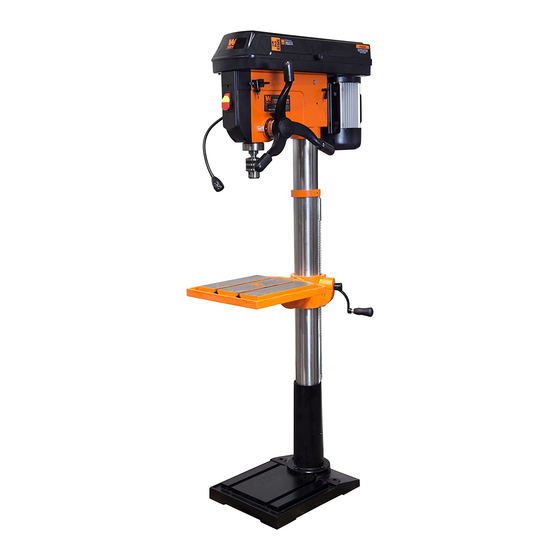
Wen 4227 Instruction Manual
17-inch 12-speed
drill press
Hide thumbs
Also See for 4227:
- Instruction manual (24 pages) ,
- Instruction manual (24 pages) ,
- User manual
Table of Contents
Advertisement
Your new tool has been engineered and manufactured to WEN's highest standards for dependability,
ease of operation, and operator safety. When properly cared for, this product will supply you years
of rugged, trouble-free performance. Pay close attention to the rules for safe operation, warnings,
and cautions. If you use your tool properly and for intended purpose, you will enjoy years of safe,
reliable service.
17-INCH 12-SPEED
IMPORTANT:
NEED HELP? CONTACT US!
Have product questions? Need technical support?
Please feel free to contact us at:
800-232-1195
techsupport@wenproducts.com
WENPRODUCTS.COM
DRILL PRESS
(M-F 8AM-5PM CST)
Model # 4227
bit.ly/wenvideo
Advertisement
Table of Contents

Related Manuals for Wen 4227


Summary of Contents for Wen 4227
-
Page 1: Drill Press
IMPORTANT: Your new tool has been engineered and manufactured to WEN’s highest standards for dependability, ease of operation, and operator safety. When properly cared for, this product will supply you years of rugged, trouble-free performance. Pay close attention to the rules for safe operation, warnings, and cautions. -
Page 2: Table Of Contents
Electrical Information Know Your Drill Press Assembly and Adjustments Operation Maintenance Troubleshooting Exploded View and Parts List Warranty TECHNICAL DATA 4227 Model Number: 120 V, 60Hz, 13A, 1-1/2 HP Motor: 180 to 2940 RPM Speed: Chuck Type: Chuck Capacity: 1/8--5/8 in. -
Page 3: General Safety Rules
GENERAL SAFETY RULES Safety is a combination of common sense, staying alert and knowing how your item works. SAVE THESE SAFE- TY INSTRUCTIONS. WARNING: To avoid mistakes and serious injury, do not plug in your tool until the following steps have been read and understood. 1. -
Page 4: Specific Safety Rules For Drill Press
GENERAL SAFETY RULES 15. DO NOT OVERREACH. Keep proper footing and balance at all times. Wear oil-resistant rubber-soled foot- wear. Keep the floor clear of oil, scrap, and other debris. 16. MAINTAIN TOOLS PROPERLY. ALWAYS keep tools clean and in good working order. Follow instruc- tions for lubricating and changing accessories. -
Page 5: Electrical Information
SPECIFIC RULES FOR DRILL PRESS 12. Do not wear gloves when operating a drill press. 13. Set the drill press to the speed that is appropriate for the material being drilled. 14. If any part of the drill press is missing/damaged or if the electrical components fail to perform properly, shut the power OFF and unplug the drill press. - Page 6 ELECTRICAL INFORMATION GUIDELINES FOR USING EXTENSION CORDS Make sure your extension cord is in good condition. When using an extension cord, be sure to use one heavy enough to carry the current your product will draw. An undersized cord will cause a drop in line voltage resulting in loss of power and overheating.
-
Page 7: Know Your Drill Press
KNOW YOUR DRILL PRESS Belt Tension Adjustment Handle Chuck Work Light Feed Handles Laser and Work Light Switches Table Spring Housing Motor Column Collar Motor Locking Wing Screw Table Locking Handle Column Bevel Scale Table Adjustment Crank Pulley Cover Rack Chuck Key Base Power Switch... -
Page 8: Assembly And Adjustments
ASSEMBLY AND ADJUSTMENTS UNPACKING Unpack the drill press and all of its parts. Compare against the list below. Do not discard the carton or any pack- aging until the drill press is completely assembled. To protect the drill press from moisture, a protective coating has been applied to the machine’s surfaces. Remove this coating with a soft cloth moistened with kerosene or WD-40®. - Page 9 ASSEMBLY AND ADJUSTMENTS WARNING: If any part is missing or damaged, do not plug the drill press in until the missing or damaged part is repaired or replaced. ASSEMBLY 1. Position the base on the floor. Attach the column to the base using four M10X30 hex head bolts (Fig.
-
Page 10: Installing The Chuck
ASSEMBLY AND ADJUSTMENTS ASSEMBLY (CONT.) 8. Assemble the hub cover (Fig. 8 - 1) and fasten it in place with a M6X16 flat head screw (Fig. 8 - 2). Attach the three handle caps (Fig. 9 -1). 9. To install the LED light assembly, connect the lamp plug contact (Fig. - Page 11 ASSEMBLY AND ADJUSTMENTS Fig. 14 Wedge Fig. 15 Fig. 13 REMOVING THE CHUCK (Fig. 13) 1. Turn the feed handles to lower the chuck to the lowest position. 2. Slide the wedge into the opening in the quill. Tap on the wedge using a hammer (not included). The chuck and arbor will drop out.
- Page 12 ASSEMBLY AND ADJUSTMENTS FEED DEPTH ADJUSTMENT Turn the depth scale ring to the desired depth (Fig. 19 - 1). Lock the scale ring in place with the depth knob (Fig. 19 - 2). The spindle will now stop after traveling the selected distance. SPEED ADJUSTMENT (FIG.
-
Page 13: Operation
OPERATION INSTALLING A DRILL BIT 1. With the switch OFF, open the chuck jaws (Fig. 23 - 1) using the chuck key (Fig. 23 - 2). Turn the chuck key counterclockwise to open the jaws. 2. Insert the drill bit (Fig. 23 - 3) into the chuck far enough to obtain the maximum gripping by the jaws, but not far enough to touch the spiral grooves of the drill bit when the jaws are tightened. - Page 14 ASSEMBLY AND ADJUSTMENTS USING THE LASER GUIDE WARNING: Do not stare directly at the laser beam. Please observe all safety rules. • Never aim the beam at a person or an object other than the workpiece. • Do not project the laser beam into the eyes of others. •...
-
Page 15: Maintenance
OPERATION DRILLING SPEEDS There are a few important factors to keep in mind when determining the best drilling speed: material type, hole size, drill bit or cutter type, and desired quality level. Smaller drill bits require greater speed than larger drill bits. Softer materials require greater speed than harder materials. -
Page 16: Troubleshooting
TROUBLESHOOTING PROBLEM CAUSES SOLUTIONS Noisy operation 1) Incorrect belt tension 1) Adjust the belt tension (See REPLACE THE 2) Dry spindle BELT section) 3) Loose spindle pulley 2) Lubricate the spindle 4) Loose motor pulley 3) Tighten the retaining nut on the pulley insert 4) Tighten the set screw on the side of the mo- tor pulley The drill bit burns or... -
Page 17: Exploded View And Parts List
EXPLODED VIEW & PARTS LIST No. Part Number Description No. Part Number Description No. Part Number Description 4227-001 Base 4227-043 Retaining ring 4227-085 Chuck key 4227-002 Column support 4227-044 Belt tension handle 4227-086 Belt house 4227-003 Hex head bolt 4227-045... - Page 18 EXPLODED VIEW & PARTS LIST...
-
Page 19: Warranty
LIMITED TWO YEAR WARRANTY WEN Products is committed to build tools that are dependable for years. Our warranties are consistent with this commitment and our dedication to quality. LIMITED WARRANTY OF WEN CONSUMER POWER TOOLS PRODUCTS FOR HOME USE GREAT LAKES TECHNOLOGIES, LLC (“Seller”) warrants to the original purchaser only, that all WEN con- sumer power tools will be free from defects in material or workmanship for a period of two (2) years from date of purchase. - Page 20 Thanks for remembering...
Need help?
Do you have a question about the 4227 and is the answer not in the manual?
Questions and answers