Roland VersaUV LEC2-300 User Manual
Hide thumbs
Also See for VersaUV LEC2-300:
- Regular maintenance manual (42 pages) ,
- Setup manual (58 pages) ,
- Product manual (43 pages)
Table of Contents
Advertisement
Quick Links
Thank you very much for purchasing this product.
• To ensure correct and safe usage with a full understanding of this product's performance, please be sure to read through this manual completely and
store it in a safe location.
• Unauthorized copying or transferal, in whole or in part, of this manual is prohibited.
• The specifications of this product and the contents of this operation manual are subject to change without notice.
• This manual and the product have been prepared and tested as much as possible. If you find any misprints or errors, please inform Roland DG Corpora-
tion.
• Roland DG Corporation assumes no responsibility for any direct or indirect loss or damage that may occur through use of this product, regardless of any
failure to perform on the part of this product.
• Roland DG Corporation assumes no responsibility for any direct or indirect loss or damage that may occur with respect to any article made using this
product.
FA01665/R1-191101
http://www.rolanddg.com/
Copyright © 2019 Roland DG Corporation
Advertisement
Table of Contents

Related Manuals for Roland VersaUV LEC2-300


Summary of Contents for Roland VersaUV LEC2-300
- Page 1 • The specifications of this product and the contents of this operation manual are subject to change without notice. • This manual and the product have been prepared and tested as much as possible. If you find any misprints or errors, please inform Roland DG Corpora- tion.
-
Page 2: Table Of Contents
Contents Chapter 1 Basic Handling Methods ....................7 1. Basic Information ..............................8 Part Names and Functions................................9 Printer Unit................................... 9 Operation Panel.................................. 13 Display Screen ..................................14 About the Media Used ................................15 Types of Media ................................... 15 Conditions for Usable Media.............................. 16 Menu List ..................................... - Page 3 Contents Preparations before Printing and Cutting Output........................77 Step 1: Printing Tests and Normal Cleaning........................77 Step 2: Adjusting Cutting ..............................79 Printing and Cutting Output ................................ 81 Step 1: Batch Settings for Printing and Cutting........................81 Step 2: Starting Output............................... 93 4.
- Page 4 Contents About the Media Take-Up Unit............................169 Other Useful Functions................................170 Performing Printing Tests Arranged Horizontally ......................170 Using Media Flanges for Paper Tubes (Cores) with an Internal Diameter of 2 Inches............171 3. Optimizing Operation Management........................172 Managing the Operations Appropriately and Efficiently ......................173 Setting the Current Date/Time and Using It for Maintenance ..................
- Page 5 Contents Light Choke Cleaning Method ............................220 When Uneven Color Issues Occur with Ink other than White Ink ..................... 222 Light Choke Cleaning Method ............................222 Handling Severe Dot Drop-out, Dot Displacement, and Uneven Colors..................224 Ink Renewal Method ................................ 224 Partially Restricting the Print Heads Used for Printing .....................
- Page 6 Contents Are you using transparent media? ........................... 255 Printing and Cutting Are Misaligned............................256 Have you corrected the misalignment of printing and cutting with crop marks? ............256 3. Media Feed Problems............................257 Media Wrinkles or Shrinks................................. 258 Is the media loaded and set up straight and securely? ....................258 Are the media clamps attached?............................
- Page 7 Contents TIME FOR MAINTENANCE ..............................271 MAINTENANCE REQUIRED ............................... 271 Error Messages ..................................272 ALIGN POINT POSITION INVALID ............................272 INK SHELF LIFE EXPIRE 12345678 ............................. 272 TEMPERATURE IS TOO HIGH **°C ............................ 272 CROPMARK ERROR NOT FOUND ............................272 CAN'T PRINT CROP CONTINUE? ............................
-
Page 8: Chapter 1 Basic Handling Methods
Chapter 1 Basic Handling Methods... -
Page 9: Basic Information
1. Basic Information Part Names and Functions ........................9 Printer Unit ........................... 9 Operation Panel .......................... 13 Display Screen..........................14 About the Media Used......................... 15 Types of Media ........................... 15 Conditions for Usable Media ...................... 16 Menu List ............................. 17 Main Menu .......................... -
Page 10: Part Names And Functions
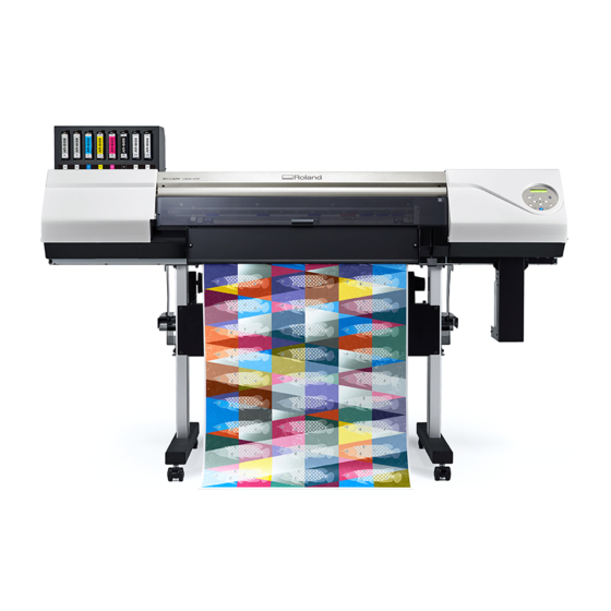
Part Names and Functions Printer Unit Front BASE PAUSE FUNCTION MENU ENTER SET UP BUSY Name Function overview Cartridge slots The location where ink cartridges are installed. Front cover Open this when necessary, such as when loading media. In all other situations, keep the front cover closed. - Page 11 Part Names and Functions Rear Name Function overview Main power switch Switch the main power on/off. Power-cord connector Use this to connect the power cable. Loading lever (rear) Operate this when you load media. Media holders Shafts Use these when you load media. Media stays UV shield (rear) Blocks the light from the UV lamp.
- Page 12 Part Names and Functions Front Cover Interior/Print Head Area Name Function overview Print-head carriage The print heads are inside here. UV-LED device Shines the UV light used to cure the ink. Cutting carriage The blade and the separating knife are inside here. Grit roller These rollers feed the media.
- Page 13 Part Names and Functions Name Function overview Grit patterns These indicate the locations of the grit rollers. When loading me- dia, be sure to place the pinch rollers within the ranges indicated by these patterns. Blade protector This is the path that the blade takes during cutting. It protects the tip of the blade.
-
Page 14: Operation Panel
Part Names and Functions Operation Panel W 720mm Part Name Details Notation in this manual Display screen This displays various setting menus and W 736mm other information. Sub power switch This switches the printer on and off. (To switch the printer off, hold down the switch for one second or longer). -
Page 15: Display Screen
Part Names and Functions Display Screen IP ADDRESS 255.255.255.255 OVER CUT ENABLE DESABLE Cursor Displays the setting to be changed. You can move it with the cursor keys. Direction mark You can select settings and switch screens by pressing the cursor keys indicating directions. -
Page 16: About The Media Used
About the Media Used Types of Media In this manual, the paper used for output is called "media." The two main types of media used in this machine are shown below. • Roll media: Media wound onto a paper tube •... -
Page 17: Conditions For Usable Media
*1 Applies to both roll and sheet media *2 To use 2-inch media, the optional media flanges are required. For information about optional items, contact your author- ized Roland DG Corporation dealer or visit our website ( http://www.rolanddg.com/ Maximum Roll Weight •... -
Page 18: Menu List
Menu List Main Menu Press [MENU]. MENU PRESET PRESET MENU PRESET NAME1 PRESET LOAD LOAD NAME1 LOAD NAME8 PRESET SAVE SAVE NAME1 NAME1 SAVE NAME8 NAME8 MENU MEDIA GAP ADJ. NO. 1 NO. 2 NO. 3 NO. 4 MENU CALIBRATION CALIBRATION CALIBRATION SETTING... - Page 19 Menu List SUB MENU SLEEP INTERVAL SLEEP INTERVAL 15min 15min SLEEP SETTING SETTING (*2) SUB MENU MAINTENANCE MAINTENANCE MAINTENANCE MAINTENANCE MENU MODEL XX-XXX XXXXXXX XXXX XXXX XXXX FIRMWARE Ver. X.XX NETWORK IP ADDRESS IP ADDRESS IP ADDRESS XXX.XXX.XXX.XXX XXX.XXX.XXX.XXX NETWORK SUBNET MASK SUBNET MASK SUBNET MASK...
- Page 20 Menu List MENU MENU F:+0.30 +0.35mm SETTING S:-0.40 -0.40mm F:+0.30 +0.35mm SETTING S:-0.40 -0.40mm (*3) RESET (*3) CALIBRATION FEED SETTING CALIBRATION FEED SETTING -0.10% -0.10% CALIBRATION SCAN SETTING SCAN SETTING -0.10% -0.10% PREFEED (*1) This is only displayed when the head height is set to SpLOW. (*2) This is only displayed when the ink type is ECO-UV4 with six colors.
-
Page 21: Function Menu
Menu List Function Menu Press [FUNCTION]. FUNCTION (*1) (*2) CLEANING FUNCTION CLEANING (*1) CLEANING NORMAL CL. CLEANING MEDIUM CL. CLEANING POWERFUL CL. CLEANING MANUAL CL. FUNCTION (*1) FUNCTION (*1) FORCE 50gf 50gf SPEED SPEED 20 cm/s 20 cm/s OFFSET 0.250mm 0.250mm UP-SPEED UP-SPEED 20 cm/s 20 cm/s... -
Page 22: Language And Unit Menu
Menu List Language and Unit Menu Hold down [MENU] and switch on the sub power. MENU LANGUAGE ENGLISH 1. Basic Information... -
Page 23: Basic Operations
2. Basic Operations Power Supply Operations........................23 Turning the Power On......................... 23 Turning the Power Off......................... 24 Precautions When Operating the Power Supply ................ 25 Sleep Mode (Power-saving Feature) ................... 26 Setup of Media............................. 27 Setup of Roll Media ........................27 Setup of Sheet Media ......................... -
Page 24: Power Supply Operations
Power Supply Operations Turning the Power On Procedure Close the front cover. Turn on the main power switch. Press the sub power button. BASE PAUSE FUNCTION MENU ENTER SET UP BUSY 2. Basic Operations... -
Page 25: Turning The Power Off
Power Supply Operations Turning the Power Off Procedure Switch off the sub power whenever printing is finished. Hold down the sub power switch for 1 second or longer. BASE PAUSE FUNCTION ENTER MENU SET UP BUSY Raise the loading lever and remove the media. When not using the machine, raise the loading lever even if the sub power is on. -
Page 26: Precautions When Operating The Power Supply
Power Supply Operations Precautions When Operating the Power Supply IMPORTANT Always keep the main power switched on. Never switch off the main power. Leaving the main power enables automatic maintenance to be carried out periodically. If the auto- matic maintenance is not carried out, it may result in the breakdown of this machine, such as the breakdown of the print heads. Never switch off the main power or unplug the power cord suddenly while operation is in progress. -
Page 27: Sleep Mode (Power-Saving Feature)
Power Supply Operations Sleep Mode (Power-saving Feature) This machine is provided with a power-saving feature that switches to a low-power "sleep mode" when a fixed interval passes with no operation. The factory default for the time after which the machine switches to sleep mode is 30 minutes. -
Page 28: Setup Of Media
The media holders of this machine are designed to be used exclusively with media that has a paper tube (core) with an inner diameter of 3 inches. To use 2-inch media, the optional media flanges are required. For information about optional items, contact your authorized Roland DG Corporation dealer or visit our website ( http:// www.rolanddg.com/... - Page 29 Setup of Media Loosen the retaining screws of the media holders, and then draw them to the left and right ends respectively. Place the media on the media stays. Point Place the media stays at positions that are 1/4 the length of the media from each end of the media. 2.
- Page 30 Setup of Media IMPORTANT Do not leave media on the media stays for a long period of time. Doing so may lead to the media becoming deformed. Exercise caution. Fit the paper tube (core) of the media onto the end cap of the left media holder. Move the right media holder to fit its end cap onto the paper tube (core) of the media.
- Page 31 Setup of Media IMPORTANT Position the left media holder correctly. If the position of the left media holder is incorrect, media may not be fed properly, which will have an adverse effect on the printing results. Use the following procedure to determine the appropriate position. Do not secure the media holders in place just yet.
- Page 32 Setup of Media Determine the positions of the media. Procedure Determine the left and right positions of the media with the grit patterns used as the reference. Note the following points when determining the positions. • Hold the media holders from the outside and move the media. •...
- Page 33 Setup of Media Pass the leading edge of the media between the pinch rollers ( ) and the grit rollers ( Point If the media cannot be loaded properly because the media suction is too weak or too strong, press [PAUSE]. Each time you press [PAUSE], the suction force is switched between three levels.
- Page 34 Setup of Media (Move to the front of the printer.) Gently hold down the media and raise the loading lever (front). The media is released. Pull out the media over the apron. 2. Basic Operations...
- Page 35 Setup of Media Finish setup. Procedure Make sure both edges of the media are above the grit rollers. Be sure to place the right edge of the media on the right-end grit roller. Move the left and right pinch rollers, placing them on both edges of the media. Position them approximately 10 mm (0.39 in.) from each edge of the media.
- Page 36 Setup of Media Move the middle pinch rollers ( ) over all the remaining grit rollers ( ) covered by the media. There are grit patterns ( ) wherever there are grit rollers. MEMO Place the middle pinch rollers over all the grit patterns within the media width. If you have forgotten to place the middle pinch rollers, the media will be skewed during printing or will come loose, which will have an effect on the printing quality.
- Page 37 Setup of Media • There may be extra middle pinch rollers depending on the width of the media being used. Be sure to remove the remaining middle pinch rollers. Hold the media at the center and pull it out, being sure to keep it straight and all areas of the media to be taut. Lower the loading lever (front).
- Page 38 Setup of Media Line up the edges of the media with the centers of the holes of the media clamps (left and right). Close the front cover. The "PRESS ENTER TO PERFORM SETUP"" message is displayed on the screen. Press [ENTER]. When you press [ENTER], the cutting carriage moves and detects the width of the media.
-
Page 39: Setup Of Sheet Media
Setup of Media Setup of Sheet Media Load the sheet media on the printer. When you have finished loading the media, [SETUP] lights. This work is refer- red to as "Setup of Media." Determine the positions of the media (sheet media). Procedure Open the front cover. - Page 40 Setup of Media Point If the media cannot be loaded properly because the media suction is too weak or too strong, press [PAUSE]. Each time you press [PAUSE], the suction force is switched between three levels. Lower the loading lever (rear). The media is held in place.
- Page 41 Setup of Media 2. Basic Operations...
- Page 42 Setup of Media Finish setup (sheet media). Procedure Make sure both edges of the media are above the grit rollers. Be sure to place the right edge of the media on the right-end grit roller. Move the left and right pinch rollers, placing them on both edges of the media. Position them approximately 10 mm (0.39 in.) from each edge of the media.
- Page 43 Setup of Media Move the middle pinch rollers ( ) over all the remaining grit rollers ( ) covered by the media. There are grit patterns ( ) wherever there are grit rollers. MEMO Place the middle pinch rollers over all the grit patterns within the media width. If you have forgotten to place the middle pinch rollers, the media will be skewed during printing or will come loose, which will have an effect on the printing quality.
- Page 44 Setup of Media • There may be extra middle pinch rollers depending on the width of the media being used. Be sure to remove the remaining middle pinch rollers. Straighten the media. Align the media with the line indicated with the arrow in the following figure. Lower the loading lever (front).
- Page 45 Setup of Media Close the front cover. The "PRESS ENTER TO PERFORM SETUP"" message is displayed on the screen. Press [ENTER]. When you press [ENTER], the cutting carriage moves and detects the width of the media. This operation is called initialization. When initialization ends, [SETUP] on the operation panel lights, and the printable width is displayed on the screen.
-
Page 46: Separating The Media
Setup of Media Separating the Media Procedure Remove the media clamps if they are attached to the machine. Close the front cover. Check that [SETUP] is lit. Press [FUNCTION]. Press [▼] several times to display the screen shown below. FUNCTION SHEET CUT Press [ENTER]. -
Page 47: What To Do First After Installation
What to Do First after Installation Accurately Adjusting the Misalignment of the Ink Landing Position This adjusts the misalignment of the ink landing position. This adjustment must be performed in the following cases. • When using this machine for the first time •... - Page 48 What to Do First after Installation Set the correction values from "NO. 1" to "NO. 4." Press [◀] or [▶] to select NO. 1 to NO. 4. Press [▲] or [▼] to select the correction value. NO. 1 NO. 2 NO.
-
Page 49: Checking Before Output
Checking before Output LAN (Local Area Network) Settings Check that you can perform communication through the LAN (Local Area Network). The LAN is enabled if the status LED ( ) on the LAN connector located on the side of the printer is lit in green. Activity LED This flashes yellow while data is being received from the network. -
Page 50: Pausing And Canceling Output
Pausing and Canceling Output You can pause and cancel output before it finishes. Pausing and Resuming Output IMPORTANT We do not recommend resuming printing because horizontal stripes are produced at the place where printing was paused. Procedure Press [PAUSE] before printing finishes. This pauses the printing operation. -
Page 51: Replacing Ink Cartridges
Replacing Ink Cartridges Out-of-ink Warnings When an ink pouch runs out, printing pauses and a warning beep sounds. Pull out the empty cartridge and insert a new one. Printing resumes. 1 2 3 4 5 6 7 8 If an ink runs out, the numbers of the color that has run out flash. Indicates that ink still remains Flashing Indicates that ink has run out... -
Page 52: Chapter 2 Output Method
Chapter 2 Output Method... -
Page 53: Printing Method
1. Printing Method Preparations before Printing Output ....................53 Checking the Daily Workflow...................... 53 Printing Tests and Normal Cleaning .................... 54 Printing Output ............................ 56 Step 1: Batch Settings for Printing ....................56 Step 2: Starting Output ....................... 64 1. Printing Method... -
Page 54: Preparations Before Printing Output
Preparations before Printing Output Checking the Daily Workflow This section explains the basic workflow of daily operations. Performing appropriate maintenance at the correct times can help prevent malfunction as well as bring out the full potential of this machine. Work start Mix white ink Turn on the sub power Any dot drop-out or dot displace-... -
Page 55: Printing Tests And Normal Cleaning
Preparations before Printing Output Printing Tests and Normal Cleaning Perform a printing test. Before you carry out actual printing, perform a printing test to ensure no dot drop-out or dot displacement occurs. If dot drop-out or dot displacement occurs, perform cleaning of the print heads (normal cleaning). MEMO •... - Page 56 Preparations before Printing Output Perform normal cleaning. Procedure Press [▼] to display the screen shown below. CLEANING NORMAL CL. Press [ENTER]. The screen shown below appears, and then cleaning starts. The (approximate) remaining time for the proce- dure is displayed on the screen. (The display shown below is an example. "01:45" = "1 minute and 45 sec- onds") CLEANING...
-
Page 57: Printing Output
Printing Output Step 1: Batch Settings for Printing To ensure the optimal output according to the media size and type, you can configure various settings on this ma- chine. However, it is hard work to configure these settings one at a time. You can use the "MEDIA SETTING" menu to configure the absolute minimum of necessary items as a batch. - Page 58 Printing Output Adjust the print head height. Procedure Press [◀] to select "CHANGE." HEAD HGT LOW [CHANGE] NEXT Press [ENTER] to confirm your entry. You can select "NEXT" and press [ENTER] to skip the current menu and proceed to the next menu. When the following screen is displayed, open the front cover.
- Page 59 Printing Output Perform position adjustment of the feed direction (reduce horizontal stripes). Feed direction means the feed direction of the media. Perform the correction adjusting to the media in advance because horizontal strips are more likely to occur during printing when the movement distance of the media changes subtly depending on the media’s thickness.
- Page 60 Printing Output REDO ADJ.? [DONE] Press [ENTER] to confirm your entry. 1. Printing Method...
- Page 61 Printing Output Adjust the misalignment of the ink landing position. Procedure Press [◀] to select "SET". MEDIA GAP ADJ. [SET] NEXT Press [ENTER] to confirm your entry. Printing of the test pattern starts. You can select "NEXT" and press [ENTER] to skip the current menu and proceed to the next menu. Press [ENTER].
- Page 62 Printing Output CUT CONFIG SET [NEXT] Press [ENTER] to confirm your entry. 1. Printing Method...
- Page 63 Printing Output Save the settings as a preset. Procedure Press [◀] to select "SAVE". PRESET [SAVE] NEXT Press [ENTER] to confirm your entry. If you select "NEXT" and press [ENTER], the screen in step 6 is displayed, and the settings you have selected up to this point are not saved as a preset.
- Page 64 Printing Output Canceling Batch Settings before They Are Completed Procedure Press [MENU] during setup. Press [◀] to select "YES". QUIT SETTING [YES] Press [ENTER] to confirm your entry. The screen shown below appears again. MENU MEDIA SETTING Selecting "NO" in step 2 returns you to the screen that was displayed when you pressed [MENU]. MEMO Even if you cancel media settings before they are completed, the values set so far will be saved.
-
Page 65: Step 2: Starting Output
Printing Output Step 2: Starting Output Never touch the print-head carriage while output is in progress. CAUTION The print-head carriage moves at high speed. Coming into contact with the moving carriage may cause injury. Procedure Before the start of daily operations, remove just the white ink cartridge, shake it 50 times (about 20 seconds), and then reinsert it. - Page 66 Printing Output • Do not open a cover (front, left, right, or the UV shield [rear]) while output is in progress. Doing so interrupts printing. • When you are performing printing with the head height set to "HIGH" or "LOW," clamp the edges of the media with the media clamps.
-
Page 67: Cutting Method
2. Cutting Method Preparations before Cutting Output ....................67 Step 1: Preventing Pulling of the Media with Undue Force............67 Step 2: Adjusting Cutting ......................68 Cutting Output ............................. 70 Step 1: Batch Settings for Cutting ....................70 Step 2: Starting Output ....................... 75 2. -
Page 68: Preparations Before Cutting Output
Preparations before Cutting Output Step 1: Preventing Pulling of the Media with Undue Force Procedure Press [MENU]. Press [▲] to display the screen shown below. MENU CUTTING MENU Press [▶] once, and then press [▲] several times to display the screen shown below. CUTTING MENU PREFEED Press [▶] to display the screen shown below. -
Page 69: Step 2: Adjusting Cutting
Preparations before Cutting Output Step 2: Adjusting Cutting For high-quality cutting, we recommend carrying out a cutting test to check the cutting quality for the media be- fore you perform actual cutting. Adjust the blade force depending on the cutting quality. Procedure Close the front cover. - Page 70 Preparations before Cutting Output Reduce the blade force. Press [ENTER] to confirm your entry. Press [▲] to display the screen shown below. CUT CONFIG TEST CUT Press [ENTER]. The test pattern is cut. Check whether the correction was successful. At the [CUT CONFIG] menu, you can also make settings for other cutting conditions in addition to the blade force. Refer to the following page.
-
Page 71: Cutting Output
Cutting Output Step 1: Batch Settings for Cutting To ensure the optimal output according to the media size and type, you can configure various settings on this ma- chine. However, it is hard work to configure these settings one at a time. You can use the "MEDIA SETTING" menu to configure the absolute minimum of necessary items as a batch. - Page 72 Cutting Output Set the blade force. For high-quality cutting, perform a cutting test to check the cutting quality for the media and adjust the blade force. Procedure Press [▶] to select "NEXT". HEAD HGT LOW CHANGE [NEXT] Press [ENTER] to confirm your entry. Press [▶] to select "NEXT".
- Page 73 Cutting Output CONTINUE ADJ.? YES [DONE] Press [ENTER] to confirm your entry. • If you select "YES", proceed to the next procedure. • If you select "DONE", proceed to step 3. Save the settings as a preset.(P. 73) Press [▲] or [▼] to adjust the blade force. •...
- Page 74 Cutting Output Save the settings as a preset. Procedure Press [▶] to select "NEXT". PRINT-CUT ADJ. SET [NEXT] Press [ENTER] to confirm your entry. Press [▶] to select "NEXT". CROP-CUT ADJ. SET [NEXT] Press [ENTER] to confirm your entry. Press [◀] to select "SAVE". PRESET [SAVE] NEXT...
- Page 75 Cutting Output Canceling Batch Settings before They Are Completed Procedure Press [MENU] during setup. Press [◀] to select "YES". QUIT SETTING [YES] Press [ENTER] to confirm your entry. The screen shown below appears again. MENU MEDIA SETTING Selecting "NO" in step 2 returns you to the screen that was displayed when you pressed [MENU]. MEMO Even if you cancel media settings before they are completed, the values set so far will be saved.
-
Page 76: Step 2: Starting Output
Cutting Output Step 2: Starting Output Never touch the print-head carriage while output is in progress. CAUTION The print-head carriage moves at high speed. Coming into contact with the moving carriage may cause injury. Procedure Close the front cover. Check that [SETUP] is lit. If [SETUP] is not lit, the setup is not completed. -
Page 77: Printing And Cutting Method
3. Printing and Cutting Method Preparations before Printing and Cutting Output ................77 Step 1: Printing Tests and Normal Cleaning ................77 Step 2: Adjusting Cutting ......................79 Printing and Cutting Output......................... 81 Step 1: Batch Settings for Printing and Cutting ................81 Step 2: Starting Output ....................... -
Page 78: Preparations Before Printing And Cutting Output
Preparations before Printing and Cutting Output Step 1: Printing Tests and Normal Cleaning Perform a printing test. Before you carry out actual printing, perform a printing test to ensure no dot drop-out or dot displacement occurs. If dot drop-out or dot displacement occurs, perform cleaning of the print heads (normal cleaning). MEMO •... - Page 79 Preparations before Printing and Cutting Output Perform normal cleaning. Procedure Press [▼] to display the screen shown below. CLEANING NORMAL CL. Press [ENTER]. The screen shown below appears, and then cleaning starts. The (approximate) remaining time for the proce- dure is displayed on the screen. (The display shown below is an example. "01:45" = "1 minute and 45 sec- onds") CLEANING...
-
Page 80: Step 2: Adjusting Cutting
Preparations before Printing and Cutting Output Step 2: Adjusting Cutting For high-quality cutting, we recommend carrying out a cutting test to check the cutting quality for the media be- fore you perform actual cutting. Adjust the blade force depending on the cutting quality. Procedure Close the front cover. - Page 81 Preparations before Printing and Cutting Output Reduce the blade force. Press [ENTER] to confirm your entry. Press [▲] to display the screen shown below. CUT CONFIG TEST CUT Press [ENTER]. The test pattern is cut. Check whether the correction was successful. At the [CUT CONFIG] menu, you can also make settings for other cutting conditions in addition to the blade force.
-
Page 82: Printing And Cutting Output
Printing and Cutting Output Step 1: Batch Settings for Printing and Cutting Note that you can set all the items set here individually as well. Start the "MEDIA SETTING" menu. Procedure Load the media. Check that the media is not sagging. If any sagging exists, settings such as the correction values will not function effectively. - Page 83 Printing and Cutting Output Adjust the print head height. Procedure Press [◀] to select "CHANGE." HEAD HGT LOW [CHANGE] NEXT Press [ENTER] to confirm your entry. You can select "NEXT" and press [ENTER] to skip the current menu and proceed to the next menu. When the following screen is displayed, open the front cover.
- Page 84 Printing and Cutting Output Perform position adjustment of the feed direction (reduce horizontal stripes). Feed direction means the feed direction of the media. Perform the correction adjusting to the media in advance because horizontal strips are more likely to occur during printing when the movement distance of the media changes subtly depending on the media’s thickness.
- Page 85 Printing and Cutting Output REDO ADJ.? [DONE] Press [ENTER] to confirm your entry. 3. Printing and Cutting Method...
- Page 86 Printing and Cutting Output Adjust the misalignment of the ink landing position. Procedure Press [◀] to select "SET". MEDIA GAP ADJ. [SET] NEXT Press [ENTER] to confirm your entry. Printing of the test pattern starts. You can select "NEXT" and press [ENTER] to skip the current menu and proceed to the next menu. Press [ENTER].
- Page 87 Printing and Cutting Output CUT CONFIG SET [NEXT] Press [ENTER] to confirm your entry. 3. Printing and Cutting Method...
- Page 88 Printing and Cutting Output Set the blade force. For high-quality cutting, perform a cutting test to check the cutting quality for the media and adjust the blade force. Procedure Press [◀] to select "SET". CUT CONFIG [SET] NEXT Press [ENTER] to confirm your entry. Press [◀] to select "SET".
- Page 89 Printing and Cutting Output Check how the two shapes peel off. • Two shapes are peeled off together/backing paper is also cut Press [◀] to select "YES". CONTINUE ADJ.? [YES] DONE • Two shapes are peeled off separately Press [▶] to select "DONE". CONTINUE ADJ.? YES [DONE] Press [ENTER] to confirm your entry.
- Page 90 Printing and Cutting Output Correct the misalignment of the printing and cutting positions. Subtle misalignment between the printing and cutting positions may occur due to the thickness of the media or the head height. We recommend that you make corrections to match the media you are using. Procedure Press [◀] to select "SET".
- Page 91 Printing and Cutting Output The point where the cutting line ( ) intersects the correction-value scale ( ) is the correction value. In the following figure, the correction value is "−0.3." Check the media feed direction (the feed direction) and the direction of print head movement (the scan direction).
- Page 92 Printing and Cutting Output Save the settings as a preset. Procedure Press [◀] to select "SAVE". PRESET [SAVE] NEXT Press [ENTER] to confirm your entry. If you select "NEXT" and press [ENTER], the screen in step 6 is displayed, and the settings you have selected up to this point are not saved as a preset.
- Page 93 Printing and Cutting Output Canceling Batch Settings before They Are Completed Procedure Press [MENU] during setup. Press [◀] to select "YES". QUIT SETTING [YES] Press [ENTER] to confirm your entry. The screen shown below appears again. MENU MEDIA SETTING Selecting "NO" in step 2 returns you to the screen that was displayed when you pressed [MENU]. MEMO Even if you cancel media settings before they are completed, the values set so far will be saved.
-
Page 94: Step 2: Starting Output
Printing and Cutting Output Step 2: Starting Output Never touch the print-head carriage while output is in progress. CAUTION The print-head carriage moves at high speed. Coming into contact with the moving carriage may cause injury. Procedure Before the start of daily operations, remove just the white ink cartridge, shake it 50 times (about 20 seconds), and then reinsert it. - Page 95 Printing and Cutting Output • Do not open a cover (front, left, right, or the UV shield [rear]) while output is in progress. Doing so interrupts printing. • When you are performing printing with the head height set to "HIGH" or "LOW," clamp the edges of the media with the media clamps.
-
Page 96: How To Cut With Crop Marks
4. How to Cut with Crop Marks Preparations before Cutting with Crop Marks ..................96 What Is Cutting with Crop Marks? ....................96 Step 1: Printing Tests and Normal Cleaning ................97 Step 2: Adjusting Cutting ......................99 Cutting with Crop Marks ........................101 Step 1: Batch Settings for Cutting with Crop Marks .............. -
Page 97: Preparations Before Cutting With Crop Marks
Preparations before Cutting with Crop Marks What Is Cutting with Crop Marks? If you are removing the printed media and loading it again in order to cut it (for example, if you are processing the media such as laminating after printing, and then loading this media again for cutting), you have to align the print- ing and cutting positions. -
Page 98: Step 1: Printing Tests And Normal Cleaning
Preparations before Cutting with Crop Marks Step 1: Printing Tests and Normal Cleaning Perform a printing test. Before you carry out actual printing, perform a printing test to ensure no dot drop-out or dot displacement occurs. If dot drop-out or dot displacement occurs, perform cleaning of the print heads (normal cleaning). MEMO •... - Page 99 Preparations before Cutting with Crop Marks Perform normal cleaning. Procedure Press [▼] to display the screen shown below. CLEANING NORMAL CL. Press [ENTER]. The screen shown below appears, and then cleaning starts. The (approximate) remaining time for the proce- dure is displayed on the screen. (The display shown below is an example. "01:45" = "1 minute and 45 sec- onds") CLEANING...
-
Page 100: Step 2: Adjusting Cutting
Preparations before Cutting with Crop Marks Step 2: Adjusting Cutting For high-quality cutting, we recommend carrying out a cutting test to check the cutting quality for the media be- fore you perform actual cutting. Adjust the blade force depending on the cutting quality. Procedure Close the front cover. - Page 101 Preparations before Cutting with Crop Marks Reduce the blade force. Press [ENTER] to confirm your entry. Press [▲] to display the screen shown below. CUT CONFIG TEST CUT Press [ENTER]. The test pattern is cut. Check whether the correction was successful. At the [CUT CONFIG] menu, you can also make settings for other cutting conditions in addition to the blade force.
-
Page 102: Cutting With Crop Marks
Cutting with Crop Marks Step 1: Batch Settings for Cutting with Crop Marks To ensure the optimal output according to the media size and type, you can configure various settings on this ma- chine. However, it is hard work to configure these settings one at a time. You can use the "MEDIA SETTING" menu to configure the absolute minimum of necessary items as a batch. - Page 103 Cutting with Crop Marks Adjust the print head height. Procedure Press [◀] to select "CHANGE." HEAD HGT LOW [CHANGE] NEXT Press [ENTER] to confirm your entry. You can select "NEXT" and press [ENTER] to skip the current menu and proceed to the next menu. When the following screen is displayed, open the front cover.
- Page 104 Cutting with Crop Marks Perform position adjustment of the feed direction (reduce horizontal stripes). Feed direction means the feed direction of the media. Perform the correction adjusting to the media in advance because horizontal strips are more likely to occur during printing when the movement distance of the media changes subtly depending on the media’s thickness.
- Page 105 Cutting with Crop Marks REDO ADJ.? [DONE] Press [ENTER] to confirm your entry. 4. How to Cut with Crop Marks...
- Page 106 Cutting with Crop Marks Adjust the misalignment of the ink landing position. Procedure Press [◀] to select "SET". MEDIA GAP ADJ. [SET] NEXT Press [ENTER] to confirm your entry. Printing of the test pattern starts. You can select "NEXT" and press [ENTER] to skip the current menu and proceed to the next menu. Press [ENTER].
- Page 107 Cutting with Crop Marks CUT CONFIG SET [NEXT] Press [ENTER] to confirm your entry. 4. How to Cut with Crop Marks...
- Page 108 Cutting with Crop Marks Set the blade force. For high-quality cutting, perform a cutting test to check the cutting quality for the media and adjust the blade force. Procedure Press [◀] to select "SET". CUT CONFIG [SET] NEXT Press [ENTER] to confirm your entry. Press [◀] to select "SET".
- Page 109 Cutting with Crop Marks Check how the two shapes peel off. • Two shapes are peeled off together/backing paper is also cut Press [◀] to select "YES". CONTINUE ADJ.? [YES] DONE • Two shapes are peeled off separately Press [▶] to select "DONE". CONTINUE ADJ.? YES [DONE] Press [ENTER] to confirm your entry.
- Page 110 Cutting with Crop Marks Correct the misalignment of the printing and cutting positions when using crop marks. When you remove the printed media, and then reload it and perform cutting, use the crop marks. For this case, correction is to be performed because the positioning of printing and cutting may be misaligned even when you are using crop marks depending on the composition of the media.
- Page 111 Cutting with Crop Marks Press [ENTER]. INPUT ADJ. VALUES Check the correction values from the test pattern (C&C2) condition. The point where the cutting line ( ) intersects the correction-value scale ( ) is the correction value. In the following figure, the correction value is "−0.3." Check the media feed direction (the feed direction) and the direction of print head movement (the scan direction).
- Page 112 Cutting with Crop Marks Save the settings as a preset. Procedure Press [◀] to select "SAVE". PRESET [SAVE] NEXT Press [ENTER] to confirm your entry. If you select "NEXT" and press [ENTER], the screen in step 6 is displayed, and the settings you have selected up to this point are not saved as a preset.
- Page 113 Cutting with Crop Marks Canceling Batch Settings before They Are Completed Procedure Press [MENU] during setup. Press [◀] to select "YES". QUIT SETTING [YES] Press [ENTER] to confirm your entry. The screen shown below appears again. MENU MEDIA SETTING Selecting "NO" in step 2 returns you to the screen that was displayed when you pressed [MENU]. MEMO Even if you cancel media settings before they are completed, the values set so far will be saved.
-
Page 114: Step 2: Starting Output With Crop Marks
Cutting with Crop Marks Step 2: Starting Output with Crop Marks Never touch the print-head carriage while output is in progress. CAUTION The print-head carriage moves at high speed. Coming into contact with the moving carriage may cause injury. Procedure Before the start of daily operations, remove just the white ink cartridge, shake it 50 times (about 20 seconds), and then reinsert it. -
Page 115: Step 3: Preparations For Cutting Output
Cutting with Crop Marks • Do not open a cover (front, left, right, or the UV shield [rear]) while output is in progress. Doing so interrupts printing. • When you are performing printing with the head height set to "HIGH" or "LOW," clamp the edges of the media with the media clamps. - Page 116 Cutting with Crop Marks Adjust cutting. For high-quality cutting, we recommend carrying out a cutting test to check the cutting quality for the media be- fore you perform actual cutting. Adjust the blade force depending on the cutting quality. Procedure Close the front cover.
- Page 117 Cutting with Crop Marks Reduce the blade force. Press [ENTER] to confirm your entry. Press [▲] to display the screen shown below. CUT CONFIG TEST CUT Press [ENTER]. The test pattern is cut. Check whether the correction was successful. At the [CUT CONFIG] menu, you can also make settings for other cutting conditions in addition to the blade force. Refer to the following page.
-
Page 118: Step 4: Starting Cutting Output
Cutting with Crop Marks Step 4: Starting Cutting Output Never touch the print-head carriage while output is in progress. CAUTION The print-head carriage moves at high speed. Coming into contact with the moving carriage may cause injury. Procedure Close the front cover. Check that [SETUP] is lit. -
Page 119: Chapter 3 Optimizing Quality And Efficiency
Chapter 3 Optimizing Quality and Efficiency... -
Page 120: Optimizing The Output Quality
1. Optimizing the Output Quality Using the Correction Functions......................120 Adjusting the Misalignment of the Ink Landing Position ............120 Accurately Adjusting the Misalignment of the Ink Landing Position ........122 Reducing Horizontal Bands (Feed Correction Function) ............124 Configuring Settings to Match the Properties of the Media .............. 126 Adjusting Print Head Height to Match Media Thickness ............ -
Page 121: Using The Correction Functions
Using the Correction Functions To optimize the output quality, it is effective to use some correction functions. Adjusting the Misalignment of the Ink Landing Position This adjusts the landing position of the ink discharged from the print heads. The landing position varies according to the print head height and the thickness of the media, so we recommend that you make corrections to match the media you are using. - Page 122 Using the Correction Functions Check that the misalignment is minimized for the two vertical lines indicated by " " (that is, the current correction value). If the misalignment is smaller for another set of vertical lines, set the correction value again.
-
Page 123: Accurately Adjusting The Misalignment Of The Ink Landing Position
Using the Correction Functions Accurately Adjusting the Misalignment of the Ink Landing Position This adjusts the landing position of the ink discharged from the print heads. You can make adjustments more accu- rately than [MEDIA GAP ADJ. SIMPLE SETTING]. The landing position varies according to the print head height and the thickness of the media, so we recommend that you make corrections to match the media you are using. - Page 124 Using the Correction Functions No.4 No.3 No.2 No.1 Set the correction values from "NO. 1" to "NO. 4." Press [◀] or [▶] to select NO. 1 to NO. 4. Press [▲] or [▼] to select the correction value. NO. 1 NO. 2 NO.
-
Page 125: Reducing Horizontal Bands (Feed Correction Function)
Using the Correction Functions Reducing Horizontal Bands (Feed Correction Function) Perform corrections to make the band-shaped "stripes" on the printed surface less noticeable. The band-shaped "stripes" are called "horizontal bands" or "banding." Horizontal bands are caused by the subtle changes in the movement distance that occur when feeding the media depending on the media's thickness. We recommend making corrections to match the media you are using. - Page 126 Using the Correction Functions CALIBRATION TEST PRINT Press [ENTER]. Printing of the test pattern starts. Check the test pattern to see whether the correction was successful. Check that the gap and overlap are the smallest for the figure indicated by " "...
-
Page 127: Configuring Settings To Match The Properties Of The Media
Configuring Settings to Match the Properties of the Media Adjusting Print Head Height to Match Media Thickness This adjusts the print head height to prevent media that is wrinkled or comes loose from the platen from contact- ing the print heads. Select the print head height from "LOW"... -
Page 128: Using Transparent Media
Configuring Settings to Match the Properties of the Media Point Even if the media clamps are removed, the message "REMOVE MEDIA CLAMPS" will be displayed when: • The media is loaded with the print head height set to "SpLOW." • The print head height is set to "SpLOW." Close the front cover. -
Page 129: Using Media That Wrinkles Easily/Does Not Move Smoothly
Configuring Settings to Match the Properties of the Media Using Media That Wrinkles Easily/Does Not Move Smoothly The platen uses suction to grip the media and keep it stable. The suction force can be adjusted corresponding to the nature and condition of the media. Procedure Press [MENU]. -
Page 130: Accurately Adjusting The Cutting Settings
Accurately Adjusting the Cutting Settings Fine-tuning the Cutting Conditions You can accurately set items such as the blade force, movement speed, and blade offset to match the nature of the media and the shape to cut. First, perform a cutting test, and then determine and enter the setting values. After entering the setting values, perform a cutting test again and check the results. - Page 131 Accurately Adjusting the Cutting Settings Display screen (cutting conditions) Setting details Default settings Set the force (pressure) of the blade. CUT CONFIG 50 gf FORCE Set the speed of cutting. CUT CONFIG 30 cm/s SPEED Set the blade offset. Enter the listed offset value for the blade. CUT CONFIG 0.250 mm The offset value for the included blade is 0.250 mm (9.8 mil).
-
Page 132: Accurately Adjusting The Cutting-In Amount
Accurately Adjusting the Cutting Settings Accurately Adjusting the Cutting-in Amount When you want to perform accurate and fine adjustment of the cutting-in amount, such as when cutting media with thin backing paper, you can obtain good results by adjusting the amount of blade extension. Turn the cap portion of the blade holder to adjust the amount of blade extension. -
Page 133: Making Adjustments When Cutting The Print Surface
Accurately Adjusting the Cutting Settings Making Adjustments When Cutting the Print Surface Hardened ink is thick. Therefore, the cutting conditions vary between cutting the print surface and cutting parts that have not been printed on. When cutting the print surface, use this [CUT TEST PRINT] function to adjust the cutting conditions. - Page 134 Accurately Adjusting the Cutting Settings Press [▲] to display the screen shown below. CUT CONFIG CUT TEST PRINT Press [ENTER]. Printing is performed as shown in the figure. : Cutting and printing test Press [▼] to display the screen shown below. CUT CONFIG TEST CUT Press [ENTER].
- Page 135 Accurately Adjusting the Cutting Settings Check item Result Setting item Adjustment The blade trace is indistinct. Increase The blade trace is too deep and cuts into the back- Reduce ing paper. The corners are not rounded and No change do not have "horns." Check the shape of the square you have peeled OFFSET...
- Page 136 Accurately Adjusting the Cutting Settings Check the adjustment results. Procedure Press [◀], [▶], [▲], or [▼] to move the cutting carriage. Align the center of the blade with the position where the cutting test can be performed on the media used for the cutting and printing test.
-
Page 137: Performing Distance Correction During Cutting
Accurately Adjusting the Cutting Settings Performing Distance Correction during Cutting This correction is performed when you want to accurately align the lengths of cut lines when cutting. This setting is also applied during cutting only, printing and cutting, or cutting with crop marks. The movement distance of the media changes subtly depending on the media's thickness. -
Page 138: Cutting To Make It Possible To Cut Corners Attractively (Over Cut)
Accurately Adjusting the Cutting Settings Cutting to Make It Possible to Cut Corners Attractively (Over Cut) Cutting the corners of the border of the cutting line slightly longer makes it possible to cut the corners attractively. This is effective when using laminated or thick media, or non-resilient media. It also has the effect of making stick- ers easier to peel off. -
Page 139: Prioritizing The Cutting Settings Of This Machine Over The Software Rip Settings
Accurately Adjusting the Cutting Settings Prioritizing the Cutting Settings of This Machine over the Software RIP Settings This setting is used to prioritize the cutting conditions set on the machine over the software RIP settings. You can also make the settings for the cutting conditions in the software RIP, and normally the software RIP settings are given priority. -
Page 140: Accurately Adjusting The Settings For Printing And Cutting
Accurately Adjusting the Settings for Printing and Cutting Correcting the Misalignment of Printing and Cutting This is a correction method performed when printing followed immediately by cutting yields positioning for print- ing and cutting that is slightly misaligned. Print alignment marks, perform detection of the printed marks, and then correct the discrepancy. Subtle misalign- ment between the printing and cutting positions may occur due to the thickness of the media or the head height. - Page 141 Accurately Adjusting the Settings for Printing and Cutting Check the test pattern to see whether the correction was successful. Check that the misalignment is minimized for the two vertical lines indicated by " " (that is, the current correction value). If the misalignment is smaller for another set of vertical lines, set the correction value again.
- Page 142 Accurately Adjusting the Settings for Printing and Cutting Correct the misalignment of printing and cutting. Procedure Press [MENU]. Press [▲] once, and then press [▶] twice to display the screen shown below. PRINT-CUT ADJ. TEST PRINT Press [ENTER]. The test pattern (P&C1) is printed and cut. The test pattern is printed at each edge of the media. MEMO If the media is tilted, the positions at the edges will be misaligned.
- Page 143 Accurately Adjusting the Settings for Printing and Cutting Press [▶]. Set the correction values for the feed direction "F" and the scan direction "S." Press [▲] or [▼] to set the correction value for the feed direction (F). F:+0.30 +0.35mm S:-0.40 -0.45mm Press [◀] or [▶] to set the correction value for the scan direction (S).
-
Page 144: Correcting The Misalignment Of The Printing And Cutting Positions During Cutting
Accurately Adjusting the Settings for Printing and Cutting Correcting the Misalignment of the Printing and Cutting Positions during Cutting This method pauses a cutting operation to correct the misalignment of the printing and cutting positions. The correction values set here are applied as the default values of the printing and cutting positions. If the printing and cutting positions are misaligned, you normally adjust the positions while checking a test pat- tern. - Page 145 Accurately Adjusting the Settings for Printing and Cutting Press [PAUSE] to display the screen shown below. TO CANCEL HOLD DOWN PAUSE KEY Press [PAUSE] again to restart the cutting operation. Hold down [PAUSE] for 1 second or longer to cancel the cutting operation. P.
-
Page 146: Accurately Adjusting The Settings For Cutting With Crop Marks
Accurately Adjusting the Settings for Cutting with Crop Marks Aligning the Positions of Cutting with Crop Marks Manually Depending on the type of media, it may not be possible to detect crop marks automatically. When crop marks cannot be detected automatically, perform alignment manually. The following figure is given as an example to explain how to manually set the base point (B) and align points ( , and The numbers for align points are determined with reference to the location of the base point, as shown in the... - Page 147 Accurately Adjusting the Settings for Cutting with Crop Marks Press [FUNCTION], then [▶] to display the screen shown below. BASE POINT ALIGN POINT 1 Press [ENTER]. The [ALIGN POINT] is set. The characters "B1" are displayed on the screen. W1100mm Repeat steps 4 through 6 to specify "align point 2"...
-
Page 148: Correcting The Misalignment Of Printing And Cutting With Crop Marks (Concurrent Test For Printing And Cutting With Crop Marks)
Accurately Adjusting the Settings for Cutting with Crop Marks Correcting the Misalignment of Printing and Cutting with Crop Marks (Concurrent Test for Printing and Cutting with Crop Marks) Depending on the composition of the media, the positioning of printing and cutting may be misaligned even when you are using crop marks. - Page 149 Accurately Adjusting the Settings for Cutting with Crop Marks Check that the misalignment is minimized for the two vertical lines indicated by " " (that is, the current correction value). If the misalignment is smaller for another set of vertical lines, set the correction value again.
- Page 150 Accurately Adjusting the Settings for Cutting with Crop Marks Correct the misalignment of printing and cutting with crop marks at the same time. Procedure Press [MENU]. Press [▲] to display the screen shown below. MENU CUTTING MENU Press [▶], then [▼][▶] to display the screen shown below. CROP-CUT ADJ.
- Page 151 Accurately Adjusting the Settings for Cutting with Crop Marks Press [▶]. Set the correction values for the feed direction "F" and the scan direction "S." Press [▲] or [▼] to set the correction value for the feed direction (F). F:+0.30 +0.35mm S:-0.40 -0.45mm Press [◀] or [▶] to set the correction value for the scan direction (S).
-
Page 152: Correcting The Misalignment Of Printing And Cutting With Crop Marks (Separate Test For Printing/Cutting With Crop Marks)
Accurately Adjusting the Settings for Cutting with Crop Marks Correcting the Misalignment of Printing and Cutting with Crop Marks (Separate Test for Printing/Cutting with Crop Marks) Due to changes in the thickness of media caused by laminating and misalignment of the loading position of the media before and after cutting, the positioning of printing and cutting may be misaligned even when you are using crop marks. - Page 153 Accurately Adjusting the Settings for Cutting with Crop Marks Check the test pattern to see whether the correction was successful. Check that the misalignment is minimized for the two vertical lines indicated by " " (that is, the current correction value). If the misalignment is smaller for another set of vertical lines, set the correction value again.
- Page 154 Accurately Adjusting the Settings for Cutting with Crop Marks Print only the crop marks. Procedure Press [MENU]. Press [▲] to display the screen shown below. MENU CUTTING MENU Press [▶], then [▼] to display the screen shown below. CUTTING MENU CROP-CUT ADJ.
- Page 155 Accurately Adjusting the Settings for Cutting with Crop Marks Perform a cutting test (separate test for printing/cutting with crop marks). Procedure Set up the media for which operations before cutting output, such as lamination, is complete. Press [◀] while the following screen is displayed. The cutting carriage comes out over the platen.
- Page 156 Accurately Adjusting the Settings for Cutting with Crop Marks Set the correction values (separate test for printing/cutting with crop marks). Procedure Press [◀], then [▼][▶] to display the screen shown below. F:+0.30 +0.35mm S:-0.40 -0.40mm View the results of the cutting test to determine the correction values. Check whether the crop mark (shaded part) and the cutting position (outer frame) are aligned.
- Page 157 Accurately Adjusting the Settings for Cutting with Crop Marks RELATED LINKS ・ P. 147 "Correcting the Misalignment of Printing and Cutting with Crop Marks (Concurrent Test for Printing and Cutting with Crop Marks)" 1. Optimizing the Output Quality...
-
Page 158: Correcting The Sensor For Reading Crop Marks
Accurately Adjusting the Settings for Cutting with Crop Marks Correcting the Sensor for Reading Crop Marks Depending on the characteristics of the media, such as reflectivity and colors, the machine may not be able to read the crop marks. In such cases, correct the sensor for reading crop marks. Correct the sensor for reading crop marks. - Page 159 • Redo the correction. CALIB. FAILED TRY AGAIN If the same message appears even after you redo correction several times, contact your authorized Roland DG Corporation dealer. Press any one of the keys on the operation panel to display the screen shown below.
- Page 160 Accurately Adjusting the Settings for Cutting with Crop Marks Check whether crop marks can be read. Procedure Press [▲] to display the screen shown below. CROPSENS CALIB SENS CHECK Press [ENTER] to display the screen shown below. MOVE CUT TOOL TO MARK CENTER Press [◀], [▶], [▲] or [▼] to move the center of the blade over the crop marks.
-
Page 161: Adjusting The Level Of The Sensor For Reading Crop Marks According To The Media
Accurately Adjusting the Settings for Cutting with Crop Marks Adjusting the Level of the Sensor for Reading Crop Marks According to the Media When the sensor for reading crop marks is corrected, the correction value is stored. When using another media, adjust the level of the sensor for reading crop marks, as the correction value may not match. -
Page 162: Resetting The Level Of The Sensor For Reading Crop Marks
Accurately Adjusting the Settings for Cutting with Crop Marks Resetting the Level of the Sensor for Reading Crop Marks When the sensor for reading crop marks is corrected, the correction value is stored. When using another media, reset the level of the sensor for reading crop marks to initial settings, as the correction value may not match. Procedure Press [MENU]. -
Page 163: Optimizing Work Efficiency
2. Optimizing Work Efficiency Using Presets............................163 Saving the Current Settings in Presets ..................163 Loading and Outputting a Preset ....................165 Adjusting the Output-start Location ....................166 Setting the Base Point....................... 166 Reducing Output Time ........................168 Speeding Up Output for Narrow Media..................168 Using the Media Take-up Unit...................... -
Page 164: Using Presets
Using Presets Saving the Current Settings in Presets Using the [PRESET] menu lets you easily change a wide variety of settings to optimize them for the media. Up to eight types of presets can be saved. You can assign a name to each one. Using media names for these may aid recognition and clarity. - Page 165 Using Presets Menu item Reference page [CALIBRATION] P. 124「Reducing Horizontal Bands (Feed Correction Function)」 [EDGE DETECTION] P. 127「Using Transparent Media」 [VACUUM POWER] P. 128「Using Media That Wrinkles Easily/Does Not Move Smoothly」 [FULL WIDTH S] P. 168「Speeding Up Output for Narrow Media」 [FORCE], [SPEED], [OFFSET], [UP-SPEED] P.
-
Page 166: Loading And Outputting A Preset
Using Presets Loading and Outputting a Preset This loads a saved preset from among the eight types of presets. If you load a preset while [SETUP] is lit, [SETUP] flashes. After that, when the setup operation is complete, [SETUP] returns to being lit. Procedure Press [MENU]. -
Page 167: Adjusting The Output-Start Location
Adjusting the Output-start Location Setting the Base Point Set the base point in order to determine the area on the loaded media in which to print (the output area). The base point ( ) indicates the right edge of the output area ( : media feed direction, : print-head car- riage movement direction). - Page 168 Adjusting the Output-start Location W1100mm 2. Optimizing Work Efficiency...
-
Page 169: Reducing Output Time
Reducing Output Time Speeding Up Output for Narrow Media This shortens output time by reducing the width of head movement to the minimum necessary. This is effective when the width of the media or the output data is narrow. Procedure Press [MENU]. -
Page 170: Using The Media Take-Up Unit
Using the Media Take-up Unit About the Media Take-Up Unit • The media take-up unit (hereinafter referred to as the "take-up unit") is an optional item. • For information on how to assemble, install, and operate the take-up unit, refer to the take-up unit user's manual. -
Page 171: Other Useful Functions
Other Useful Functions Performing Printing Tests Arranged Horizontally When performing printing tests successively, you can select "FEED" (vertical printing) or "SCAN" (horizontal print- ing) as the print position for the second and later tests in comparison to the first test. If you are using the optional media take-up unit, printing tests will be printed with the "FEED"... -
Page 172: Using Media Flanges For Paper Tubes (Cores) With An Internal Diameter Of 2 Inches
Using Media Flanges for Paper Tubes (Cores) with an Internal Diameter of 2 Inches The media flanges for paper tubes (cores) with an internal diameter of 2 inches are optional items. For information about purchasing them, contact your authorized Roland DG Corporation dealer or visit our website ( https:// www.rolanddg.co.jp... -
Page 173: Optimizing Operation Management
3. Optimizing Operation Man- agement Managing the Operations Appropriately and Efficiently..............173 Setting the Current Date/Time and Using It for Maintenance..........173 Displaying the Amount of Media Remaining ................174 Making Sure to Verify the Setting for the Amount Remaining Every Time the Media Is Changed ............................ -
Page 174: Managing The Operations Appropriately And Efficiently
Managing the Operations Appropriately and Effi- ciently Setting the Current Date/Time and Using It for Maintenance Set the current date/time. By setting this, when you perform a printing test the printing test date and time will be printed alongside the printed test pattern. Procedure Press [MENU]. -
Page 175: Displaying The Amount Of Media Remaining
Managing the Operations Appropriately and Efficiently Displaying the Amount of Media Remaining You can display how much of the media in use is left. By setting the amount of media currently remaining at the start, the amount remaining will be constantly displayed on the screen until it reaches zero. If you remove the media or cancel media loading by raising the loading lever, the amount remaining at that time flashes on the screen. -
Page 176: Making Sure To Verify The Setting For The Amount Remaining Every Time The Media Is Changed
Managing the Operations Appropriately and Efficiently Making Sure to Verify the Setting for the Amount Remaining Every Time the Media Is Changed Set the machine to display the amount of media remaining every time the media is changed. Setting this menu item to "ENABLE" can keep you from forgetting to redo the setting when you change the media. However, be sure to also set the [EDGE DETECTION] menu item to "ENABLE"... -
Page 177: Printing The Amount Of Remaining Media
Managing the Operations Appropriately and Efficiently Printing the Amount of Remaining Media This prints the amount of media remaining, which is displayed on the top menu. Use this when you want to make a record of the remaining length of the media currently in use. Printing the amount of media remaining before you change the media enables you to refer to the printed record and use the value to make the setting for the remaining amount the next time you use the media. -
Page 178: Determining What Happens When Ink Runs Out
Managing the Operations Appropriately and Efficiently Determining What Happens When Ink Runs Out This menu lets you determine the operation that takes place when an ink cartridge becomes empty during print- ing. The print quality will be affected by the selected operation. Procedure Press [MENU]. -
Page 179: Notifying The User Of Ink Exceeding Its Shelf Life
Managing the Operations Appropriately and Efficiently Notifying the User of Ink Exceeding Its Shelf Life Use this menu item to set the machine so that a warning message ("INK SHELF LIFE EXPIRE") is displayed on the screen when the ink's shelf life is exceeded. This message is displayed when the sub power is turned on for the first time after the ink has expired. -
Page 180: Checking The Ink Shelf Life
Managing the Operations Appropriately and Efficiently Checking the Ink Shelf Life You can use the display to check the shelf lives of the inks in slots 1 to 8. Procedure Press [MENU]. Press [▼] several times to display the screen shown below. MENU INK SHELF LIFE Press [▶], then [▼] to display the screen shown below. -
Page 181: Setting The Activation Interval For Sleep Mode (Power-Saving Feature)
Managing the Operations Appropriately and Efficiently Setting the Activation Interval for Sleep Mode (Power-saving Feature) This setting is used to set how long it should take until the machine goes into sleep mode (the state in which the power-saving feature is working) when no print data is received and no operations are performed for a continued length of time. -
Page 182: Deactivating The Sleep Mode (Power-Saving Feature)
Managing the Operations Appropriately and Efficiently Deactivating the Sleep Mode (Power-saving Feature) This setting is used to set the machine so that it never goes into sleep mode (the state in which the power-saving feature is working) when no print data is received and no operations are performed for a continued length of time. Procedure Press [MENU]. -
Page 183: Managing The Basic Settings Of The Printer
Managing the Basic Settings of the Printer Setting the Menu Language and Units of Measurement This feature sets the language and units of measurement displayed on the display screen of the operation panel. Procedure Hold down [MENU] and switch on the sub power. Press [▲] or [▼] to select the display (menu) language. -
Page 184: Viewing System Information
Managing the Basic Settings of the Printer Viewing System Information This is a method for viewing system information of this machine, such as serial number and ink type. Procedure Press [MENU]. Press [▼] several times to display the screen shown below. MENU SYSTEM INFO. -
Page 185: Returning All Settings To Factory Defaults
Managing the Basic Settings of the Printer Returning All Settings to Factory Defaults This menu returns all settings to the same as their factory defaults. The settings for [MENU LANGUAGE], [LENGTH UNIT], and [TEMP. UNIT] are not returned to their factory default values. -
Page 186: Chapter 4 Maintenance
Chapter 4 Maintenance... -
Page 187: Introduction
1. Introduction Important Notes on Handling and Use ....................187 Printer............................187 Ink Cartridges..........................187 Basic Maintenance Knowledge ......................188 Types and Timing of Maintenance.................... 188 Automatic Maintenance Feature and Notes................189 Measures When the Printer Is Not in Use for a Prolonged Period ........... 190 1. -
Page 188: Important Notes On Handling And Use
Ink Cartridges • Ink cartridges come in various types. • Use a type that is compatible with the printer. Also, be sure to use only genuine items from Roland DG Corporation. • Never subject to impact or attempt to disassemble. -
Page 189: Basic Maintenance Knowledge
Basic Maintenance Knowledge Types and Timing of Maintenance To use this machine under its optimal conditions, it is important to perform the appropriate maintenance at the appropriate times. Regular Maintenance These are the maintenance items that are required on a daily basis. Timing Category Item... -
Page 190: Automatic Maintenance Feature And Notes
Basic Maintenance Knowledge Automatic Maintenance Feature and Notes This machine has a feature that automatically performs maintenance periodically. This function performs operations for preventing the print heads from drying out, so: • Always keep the main power switched on. • Do not leave the front cover open for a long time. •... -
Page 191: Measures When The Printer Is Not In Use For A Prolonged Period
Basic Maintenance Knowledge Measures When the Printer Is Not in Use for a Prolonged Period Be sure to follow the instructions shown below when the printer is not in use for a prolonged period. • Empty the drain bottle. If you know that you will not use the machine for a prolonged period, empty the drain bottle. When the main power is on, the machine periodically performs automatic maintenance in which fluid is discharged. -
Page 192: Regular Maintenance
2. Regular Maintenance Cleaning the Machine ........................192 Cleaning the Media Path......................192 Cleaning the Cutting Carriage Roller..................193 Disposing of Discharged Fluid ......................194 Precautions for Disposing of Discharged Fluid................194 If the Discharged Fluid Disposal Message Appears..............195 If the Drain Bottle Exceeds Its Capacity Limit ................ -
Page 193: Cleaning The Machine
Cleaning the Machine Cleaning the Media Path Wipe away any ink or grime on the media path and other areas as part of the daily cleaning procedure. It is easy for ink or grime to affix to the media path, and, if left unattended, this will contaminate new media and have a negative effect on the transport of media when it is output. -
Page 194: Cleaning The Cutting Carriage Roller
Cleaning the Machine Cleaning the Cutting Carriage Roller Paper dust affixes to the separating knife carriage roller during media separation. Periodically wipe the area clean. Never use a solvent such as gasoline, alcohol, or thinner to perform cleaning. WARNING Doing so may cause fire. Before attempting cleaning, switch off the sub power and wait until the UV-LED device CAUTION cools (approximately 15 minutes). -
Page 195: Disposing Of Discharged Fluid
Disposing of Discharged Fluid Precautions for Disposing of Discharged Fluid Never place discharged fluid or ink near an open flame. WARNING Doing so may cause fire. To store discharged fluid temporarily, place it in the included drain bottle or in a durable CAUTION sealed container such as a metal can or polyethylene tank, and cap the container tightly. -
Page 196: If The Discharged Fluid Disposal Message Appears
Disposing of Discharged Fluid If the Discharged Fluid Disposal Message Appears The message shown below appears when a certain amount of discharged fluid has collected in the bottle and the sub power is turned on. If this message appears, dispose of the discharged fluid. EMPTY DRAIN BOTTLE Procedure... -
Page 197: If The Drain Bottle Exceeds Its Capacity Limit
Disposing of Discharged Fluid If the Drain Bottle Exceeds Its Capacity Limit The drain bottle collects discharged fluid. When the drain bottle is full, the message shown below will be dis- played. No more discharged fluid can be stored in the drain bottle, so be sure to discard the discharged fluid be- fore the drain bottle exceeds its capacity limit. -
Page 198: Maintenance That Must Be Performed Daily
Maintenance That Must Be Performed Daily Maintenance of Ink Cartridges The precipitation of the ingredients in the ink disables printing in normal color. So that the ink mixes well, shake the ink cartridge horizontally with a stroke length of around 5 cm (2 in.) from each end of the ink cartridge. •... -
Page 199: Manual Cleaning
Maintenance That Must Be Performed Daily If you have opened the front cover, close it. If no dot drop-out or dot displacement occurs, this operation is finished. Press [FUNCTION] to go back to the original screen. Perform normal cleaning. Procedure Press [▼] to display the screen shown below. -
Page 200: When Normal Cleaning Is Not Effective
When Normal Cleaning Is Not Effective Medium Cleaning Method The print heads are important components that discharge ink. They require periodic and appropriate mainte- nance. When problems such as dot drop-out are not resolved by normal cleaning ( Printing Tests and Normal Cleaning(P. ), perform the more forceful "medium cleaning"... -
Page 201: Powerful Cleaning Method
When Normal Cleaning Is Not Effective Powerful Cleaning Method The print heads are important components that discharge ink. They require periodic and appropriate mainte- nance. When problems such as dot drop-out are not resolved by medium cleaning ( Medium Cleaning Method(P. 199) perform the more forceful "powerful cleaning"... -
Page 202: Manual Cleaning
Manual Cleaning When Manual Cleaning Is Necessary The print heads are important components that discharge ink. They require periodic and appropriate mainte- nance. It is important to perform manual cleaning with the appropriate timing. After daily operations are finished Be sure to perform manual cleaning after daily operations are finished. When symptoms that cannot be improved with powerful cleaning occur When any of the symptoms given below occur and powerful cleaning is not effective, perform manual cleaning. -
Page 203: Manual Cleaning Method
• Stroke the sponges very gently, applying as little pressure as possible. Never rub, scrape, or crush them. • If you use up the cleaning sticks or cleaning liquid, contact your authorized Roland DG Corporation dealer or visit our website http://www.rolanddg.com/... - Page 204 Manual Cleaning Also, the print head moves to the left end of the platen. FINISHED? IMPORTANT Do not press [ENTER] at this stage. Press the [ENTER] key after cleaning is complete. If you press the [ENTER] key at this stage, wait for the screen to change as shown in the following figure, and then press the [ENTER] key again.
- Page 205 Manual Cleaning Move the print-head carriage to the left end. Move the print-head carriage by hand. When moving the print-head carriage by hand, be sure to hold the specified posi- CAUTION tion. Moving it by holding positions other than those specified may deform and damage the cover. : Position to hold with your hand Apply a large amount of cleaning liquid to the cleaning stick.
- Page 206 Manual Cleaning Clean the locations shown in the following figure. Be especially careful to clean away any fibrous dust (lint). Use the wide surface of the cleaning stick to wipe off the left side. Then, use the opposite surface (which is not dirty) to wipe off the right side.
- Page 207 Manual Cleaning Move the print-head carriage by hand. When moving the print-head carriage by hand, be sure to hold the specified posi- CAUTION tion. Moving it by holding positions other than those specified may deform and damage the cover. : Position to hold with your hand Attach the cut rail.
- Page 208 Manual Cleaning Clean the print head caps. Procedure Open the right cover. Clean the locations shown in the following figure. Be especially careful to clean away any fibrous dust (lint). After wiping off the hooked side of the wiper (a) with a cleaning stick, wipe off the opposite side (b). Wipe off the area in the figure with a cleaning stick.
- Page 209 Manual Cleaning Remove any hardened ink on top of the print head caps. Use a pair of tweezers to remove the pieces of hardened ink that are 3 mm (0.12 in.) or more in length. IMPORTANT Do not use excessive force when pulling on pieces of hardened ink that are difficult to remove. Doing so may damage the print head caps.
- Page 210 Manual Cleaning The screen shown below appears, and then cleaning starts. The (approximate) remaining time for the proce- dure is displayed on the screen. (The display shown below is an example. "01:45" = "1 minute and 45 sec- onds") CLEANING... >>...
- Page 211 Manual Cleaning Perform a printing test to check the results. Procedure Load the media. P. 27「Setup of Media」 Press [FUNCTION]. Press [▼], then [▶] to display the screen shown below. CLEANING TEST PRINT Press [ENTER]. Printing of the test pattern starts. Check whether there is dot drop-out or dot displacement in the test pattern.
-
Page 212: Consumable Products And Parts Related To Manual Cleaning
The cleaning sticks, cleaning liquid, and print heads are consumable products or consumable parts. • If you use up the cleaning sticks and cleaning liquid used for manual cleaning, contact your authorized Roland DG Corporation dealer or visit our website ( http://www.rolanddg.com/... -
Page 213: Cleaning That Must Be Performed Once A Month Or More
• The frequency with which UV-LED device cleaning is required depends on the machine's use. For information about the frequency of cleaning needed for your conditions of use, contact your authorized Roland DG Corporation dealer. • For hardened ink and other such dirt that cannot be completely cleaned away, contact your authorized Roland DG Corporation deal- 2. Regular Maintenance... -
Page 214: How To Clean The Uv-Led Devices
Cleaning That Must Be Performed Once a Month or More How to Clean the UV-LED Devices IMPORTANT Important notes on this procedure • Before attempting this operation, remove any media. • To prevent the print heads from drying out, finish this procedure in 10 minutes or less. A warning beep sounds after 10 minutes. •... - Page 215 Cleaning That Must Be Performed Once a Month or More CLEANING MANUAL CL. Open the front cover. Open the left covers (top and bottom). Remove the cut rail. Touch the location shown in the figure to discharge any static electricity. Move the print-head carriage to the left end.
- Page 216 Cleaning That Must Be Performed Once a Month or More Move the print-head carriage by hand. When moving the print-head carriage by hand, be sure to hold the specified posi- CAUTION tion. Moving it by holding positions other than those specified may deform and damage the cover. : Position to hold with your hand Wet a cloth with anhydrous ethanol or isopropyl alcohol, and then wipe off the base and irradiation unit of each UV lamp with this cloth.
- Page 217 Cleaning That Must Be Performed Once a Month or More When you have finished cleaning, move the print-head carriage to above the platen. Move the print-head carriage by hand. When moving the print-head carriage by hand, be sure to hold the specified posi- CAUTION tion.
- Page 218 Cleaning That Must Be Performed Once a Month or More : Position to hold with your hand Attach the cut rail. Close the left covers (top and bottom). Close the front cover. Press [ENTER]. The screen shown below appears, and then head cleaning starts. CLEANING...
-
Page 219: Advanced Maintenance
3. Advanced Maintenance When Uneven Color Issues Occur with White Ink ................219 Ink Circulating Method ......................219 Light Choke Cleaning Method....................220 When Uneven Color Issues Occur with Ink other than White Ink............222 Light Choke Cleaning Method....................222 Handling Severe Dot Drop-out, Dot Displacement, and Uneven Colors .......... -
Page 220: When Uneven Color Issues Occur With White Ink
When Uneven Color Issues Occur with White Ink Ink Circulating Method If uneven color issues with white ink are not resolved even after shaking the ink cartridges to mix the ink, perform "ink circulation." Uneven colors refers to the symptom of printed colors being uneven (such as the color density being inconsistent) even when the same data is printed with the same settings. -
Page 221: Light Choke Cleaning Method
When Uneven Color Issues Occur with White Ink Light Choke Cleaning Method If problems still remain even after circulating the ink, perform "light choke cleaning." Light choke cleaning can be used to stabilize the output colors by agitating the ink. IMPORTANT Light choke cleaning consumes a lot of ink, and overly frequent use may damage the print heads themselves. - Page 222 When Uneven Color Issues Occur with White Ink Failing to discard the discharged fluid when [EMPTY DRAIN BOTTLE] is displayed will lead to the discharged fluid overflowing during cleaning. Before you detach the drain bottle, be sure to wait for the screen to display "EMPTY CAUTION DRAIN BOTTLE."...
-
Page 223: When Uneven Color Issues Occur With Ink Other Than White Ink
When Uneven Color Issues Occur with Ink other than White Ink Light Choke Cleaning Method Perform this cleaning when printed colors are unstable or uneven, e.g., when color density is inconsistent, even if the same data is printed with the same settings. This will stabilize the output colors by agitating the ink. IMPORTANT Light choke cleaning consumes a lot of ink, and overly frequent use may damage the print heads themselves. - Page 224 When Uneven Color Issues Occur with Ink other than White Ink Failing to discard the discharged fluid when [EMPTY DRAIN BOTTLE] is displayed will lead to the discharged fluid overflowing during cleaning. Before you detach the drain bottle, be sure to wait for the screen to display "EMPTY CAUTION DRAIN BOTTLE."...
-
Page 225: Handling Severe Dot Drop-Out, Dot Displacement, And Uneven Colors
Handling Severe Dot Drop-out, Dot Displacement, and Uneven Colors Ink Renewal Method Perform the procedure below if ink discharge issues such as dot drop-out are not corrected after performing cleaning using the cleaning function (normal, medium, powerful) or manual cleaning. IMPORTANT A large amount of ink will be discharged during this operation. - Page 226 Handling Severe Dot Drop-out, Dot Displacement, and Uneven Colors Failing to discard the discharged fluid when [EMPTY DRAIN BOTTLE] is displayed will lead to the discharged fluid overflowing during cleaning. Before you detach the drain bottle, be sure to wait for the screen to display "EMPTY CAUTION DRAIN BOTTLE."...
-
Page 227: Partially Restricting The Print Heads Used For Printing
Handling Severe Dot Drop-out, Dot Displacement, and Uneven Colors Partially Restricting the Print Heads Used for Printing When dot drop-out or dot displacement is not improved even after replacing the ink, partially restrict the print heads to use for printing (i.e. prevent the use of the print heads that are causing discharge issues). This operation is called the "nozzle mask,"... - Page 228 Handling Severe Dot Drop-out, Dot Displacement, and Uneven Colors Limit the print heads used for printing. Procedure Start VersaWorks. Click [Printer] - [Printer Settings]. The [Printer Settings] dialog box appears. From the [Printer List], select the printer whose print heads will be limited. Click [Advanced].
-
Page 229: Emergency Measure) Cleaning The Print Head Surface
This operation is an emergency measure. It may damage defect-free parts depending on the symptoms, worsening the symptoms. If you have any questions, contact your authorized Roland DG Corporation dealer. Procedure Apply a large amount of cleaning liquid to the cleaning stick. -
Page 230: Replacing Consumable Parts
4. Replacing Consumable Parts Replacing Parts for Maintenance ....................... 230 Replacing the Wipers........................ 230 Replacing the Felt Wipers ......................233 Replacing the Blade/Separating Knife....................236 Replacing the Blade ........................236 Replacing the Separating Knife ....................241 Inquiries for Consumable Parts and Products..................243 Items That You Can Purchase and Replace by Yourself............. -
Page 231: Replacing Parts For Maintenance
When the following screen is displayed, it is time to replace the wiper. TIME FOR WIPER REPLACE For information about purchasing wipers, contact your authorized Roland DG Corporation dealer or visit our web- site ( http://www.rolanddg.com/ Be sure to perform operations as specified by the instructions, and never touch any area CAUTION not specified in the instructions. - Page 232 Replacing Parts for Maintenance Preparation is complete once the following screen is displayed. FINISHED? IMPORTANT Do not press [ENTER] at this stage. Press [ENTER] after replacing the wiper. If you press [ENTER] at this stage, close the right cover according to the instructions on the screen, wait for the following screen to be displayed, and then press [ENTER] again. MAINTENANCE REPLACE WIPER Touch the location shown in the figure to discharge any static electricity.
- Page 233 Replacing Parts for Maintenance Press [ENTER]. When the following screen is displayed, close the right cover. CLOSE COVER R When the following screen is displayed again, the wiper replacement is finished. MAINTENANCE REPLACE WIPER Press [MENU] to go back to the original screen. 4.
-
Page 234: Replacing The Felt Wipers
When the following screen is displayed, it is time to replace the wiper. TIME FOR FELT REPLACE For information about purchasing felt wipers, contact your authorized Roland DG Corporation dealer or visit our website ( http://www.rolanddg.com/ Be sure to perform operations as specified by the instructions, and never touch any area CAUTION not specified in the instructions. - Page 235 Replacing Parts for Maintenance Preparation is complete once the following screen is displayed. FINISHED? IMPORTANT Do not press [ENTER] at this stage. Press [ENTER] after replacing the wiper. If you press [ENTER] at this stage, close the right cover according to the instructions on the screen, wait for the following screen to be displayed, and then press [ENTER] again. MAINTENANCE REPLACE FELT Touch the location shown in the figure to discharge any static electricity.
- Page 236 Replacing Parts for Maintenance Press [ENTER]. When the following screen is displayed, close the right cover. CLOSE COVER R When the following screen is displayed again, the wiper replacement is finished. MAINTENANCE REPLACE FELT Press [MENU] to go back to the original screen. 4.
-
Page 237: Replacing The Blade/Separating Knife
Replacing the Blade/Separating Knife Replacing the Blade If the blade becomes dull, if the edge of the blade is chipped, or if the cutting quality is lowered, replace the blade with a new blade. Be sure to perform operations as specified by the instructions, and never touch any area CAUTION not specified in the instructions. - Page 238 Replacing the Blade/Separating Knife Replace the blade. Press the pin (A) to push out the old blade (B). Insert a new blade (C). Orient the tip of the blade (D) correctly. Install the cutting tool in the cutting carriage. Not OK Tighten the screw.
- Page 239 Replacing the Blade/Separating Knife MAINTENANCE REPLACE KNIFE Press [MENU] to go back to the original screen. Make adjustments according to the new blade. Procedure Close the front cover. Press [◀], [▶], [▲], or [▼] to move the cutting carriage to the location where you want to carry out the cutting test. You can freely set the location for the cutting test.
- Page 240 Replacing the Blade/Separating Knife Press [▲] or [▼] to select the cutting condition you want to set. Display screen (cutting conditions) Setting details Default settings Set the force (pressure) of the blade. CUT CONFIG 50 gf FORCE Set the speed of cutting. CUT CONFIG 30 cm/s SPEED...
- Page 241 Replacing the Blade/Separating Knife Set the amount of blade extension ( ) to an amount that is the sum of the thickness of the material portion ) and half ( ) the thickness of the backing paper ( • Rough Estimate for the Amount of Blade Extension (When Cutting Perforated Lines) Set the amount of blade extension ( ) so that when the blade pierces the media ( ), the blade tip extends...
-
Page 242: Replacing The Separating Knife
Replacing the Blade/Separating Knife Replacing the Separating Knife If the separating knife becomes dull, replace it with the included replacement knife. Be sure to perform operations as specified by the instructions, and never touch any area CAUTION not specified in the instructions. Otherwise sudden movement of the machine may cause injury. - Page 243 Replacing the Blade/Separating Knife Install a new knife. Slide the knife to align it with the groove ( ). The knife is secured in place by the magnet( Slowly insert the knife into the groove. Tighten the screw. Take care to ensure that the knife does not slip out of position at this time. Close the front cover.
-
Page 244: Inquiries For Consumable Parts And Products
Inquiries for Consumable Parts and Products Items That You Can Purchase and Replace by Yourself To purchase the following consumable parts or products, contact your authorized Roland DG Corporation dealer or visit our website ( http://www.rolanddg.com/ Item Related page Wiper P. -
Page 245: Chapter 5 Troubleshooting Methods
Chapter 5 Troubleshooting Methods... -
Page 246: Output Quality Problems
1. Output Quality Problems Printed Results Are Coarse or Contain Horizontal Stripes..............246 Do the print heads cause dot drop-out?................... 246 Is the print head height appropriate?..................246 Have you carried out feed correction? ..................246 Have you carried out correction of the ink landing position (MEDIA GAP ADJ.)?..... 246 Is the printer installed in a level and stable location? .............. -
Page 247: Printed Results Are Coarse Or Contain Horizontal Stripes
Printed Results Are Coarse or Contain Horizontal Stripes Do the print heads cause dot drop-out? Carry out a printing test and make sure no dot drop-out or dot displacement occurs. If dot drop-out or dot dis- placement is present, perform head cleaning. RELATED LINKS ・ ... -
Page 248: Are The Settings For The [Preset] Menu Item Appropriate
Printed Results Are Coarse or Contain Horizontal Stripes RELATED LINKS ・ P. 27 "Setup of Roll Media" ・ P. 38 "Setup of Sheet Media" Are the settings for the [PRESET] menu item appropriate? If the settings selected with the [PRESET] menu item are not suitable for the type of media, printing may be ad- versely affected. -
Page 249: The Media Becomes Soiled When Printed
The Media Becomes Soiled When Printed Do the print heads come into contact with the media? The height of the print heads may be too low. Also, if the media is not loaded and set up correctly, it may wrinkle or come loose and contact the print heads. -
Page 250: Colors Are Unstable Or Uneven
Colors Are Unstable or Uneven Did you shake the ink cartridges before installing them? Shake new ink cartridges 50 times (about 20 seconds) before you install them. Every day before starting work, remove the white ink cartridge, shake it 50 times (about 20 seconds), and then reinsert it. - Page 251 Colors Are Unstable or Uneven RELATED LINKS ・ P. 163 "Using Presets" 1. Output Quality Problems...
-
Page 252: Cutting Is Misaligned Or Skewed
Cutting Is Misaligned or Skewed Is the media loaded correctly? If the media is not loaded correctly or the media feed is not smooth, printing may be adversely affected. Load the media correctly. RELATED LINKS ・ P. 27 "Setup of Roll Media" ・ ... -
Page 253: Are The Pinch Rollers Placed On The Proper Locations
Cutting Is Misaligned or Skewed Are the pinch rollers placed on the proper locations? Be sure to place the pinch rollers on the grit rollers. If the pinch rollers are not placed on the proper locations, misalignment of the media may occur. RELATED LINKS ・ ... -
Page 254: Printing And Cutting Are Misaligned
Printing and Cutting Are Misaligned Have you corrected the misalignment of printing and cutting? Misalignment between the printing and cutting positions may occur due to the thickness of the media or the head height. Make corrections for misaligned printing and cutting for the media you are using. RELATED LINKS ・ ... -
Page 255: Problems In Cutting With Crop Marks
2. Problems in Cutting with Crop Marks Automatic Detection of Crop Marks Fails ..................255 Is the media wrinkled or warped? .................... 255 Is the media size too large? ...................... 255 Are you using media that is likely to reflect light? ..............255 Are you using transparent media?.................... -
Page 256: Automatic Detection Of Crop Marks Fails
Automatic Detection of Crop Marks Fails Is the media wrinkled or warped? Wrinkled or warped media may cause crop mark detection to fail. Avoid using wrinkled or warped media. If the crop marks cannot be detected automatically, you can perform alignment manually. RELATED LINKS ・ ... -
Page 257: Printing And Cutting Are Misaligned
Printing and Cutting Are Misaligned Have you corrected the misalignment of printing and cutting with crop marks? Depending on the composition of the media, the positioning of printing and cutting may be misaligned even when you are using crop marks. Make corrections for misaligned printing and cutting for the media you are using. RELATED LINKS ・ ... -
Page 258: Media Feed Problems
3. Media Feed Problems Media Wrinkles or Shrinks ......................... 258 Is the media loaded and set up straight and securely? ............258 Are the media clamps attached? ....................258 Is the humidity of the room too high?..................258 Is the media sagging? ....................... 258 Media Feeding Is Not Straight...................... -
Page 259: Media Wrinkles Or Shrinks
Media Wrinkles or Shrinks Is the media loaded and set up straight and securely? Feeding is not smooth when the media is not straight or is tensioned unevenly on the left and right. Reload the media. RELATED LINKS ・ P. 27 "Setup of Roll Media" ・ ... -
Page 260: Media Feeding Is Not Straight
Media Feeding Is Not Straight Is the media loaded and set up straight and securely? Feeding is not smooth when the media is not straight or is tensioned unevenly on the left and right. Reload the media. RELATED LINKS ・ P. 27 "Setup of Roll Media" ・ ... -
Page 261: Media Feeding Is Not Smooth
Media Feeding Is Not Smooth Is some other object coming into contact with the media? Make sure the media does not touch anything else. This may affect output, even when the feed appears to be smooth. RELATED LINKS ・ P. 27 "Setup of Roll Media" ・ ... -
Page 262: A Media Jam Occurs
A Media Jam Occurs! Is an error message displayed? If an error message is displayed because the media has jammed, immediately correct the problem. Doing so may damage the print heads. RELATED LINKS ・ P. 274 "MOTOR ERROR TURN POWER OFF" Is the media warped or wrinkled? Many factors can cause warping or wrinkling. -
Page 263: Is The Media Too Thick
A Media Jam Occurs! ・ P. 38 "Setup of Sheet Media" Is the media too thick? Media that is too thick may not only cause an unstable feed but may scrape the print heads, resulting in a malfunc- tion. Never use such media. 3. -
Page 264: Machine Problems
4. Machine Problems The Print Heads Do Not Move ......................264 What to Do First........................264 If the Heads Still Do Not Move ....................264 The Printer Unit Does Not Run ......................266 Is the power switched on?......................266 Is [SETUP] lit?..........................266 Are any covers open?........................ -
Page 265: The Print Heads Do Not Move
If the Heads Still Do Not Move If the heads still do not move, carry out the following emergency response measure, and then contact your au- thorized Roland DG Corporation dealer. Procedure Switch off the main power, and then open the front cover. - Page 266 The Print Heads Do Not Move Gently apply pressure from the right side to make sure the print-head carriage does not move to the left. If the print-head carriage moves to the left, again move it slowly by applying pressure from the left side and make sure it locks in place.
-
Page 267: The Printer Unit Does Not Run
The Printer Unit Does Not Run Is the power switched on? Switch on the printer's main power, and then press the sub power switch and make sure the sub power switch lights. RELATED LINKS ・ P. 23 "Turning the Power On" Is [SETUP] lit? Output is not performed when [SETUP] is not lit. -
Page 268: Is The Lan Routing Appropriate
The Printer Unit Does Not Run RELATED LINKS ・ LEC2-300 Setup Guide (https://webmanual.rolanddg.com/LEC2-300) Is the LAN routing appropriate? Check whether or not the network routing is appropriate. Try connecting the computer and the machine to the same hub or connecting them directly using a cable. If this makes it possible to perform output, it means the prob- lem may be in the network itself. -
Page 269: Cannot Separate The Media
Cannot Separate the Media Is the separating knife installed? If the separating knife is not installed, you cannot separate the media. RELATED LINKS ・ P. 241 "Replacing the Separating Knife" Is the cut rail installed? If the cut rail is not installed, you cannot separate the media. If the cut rail is not installed, remove the left cover, and then install the cut rail according to the figure shown below. -
Page 270: Messages On The Operation Panel
5. Messages on the Operation Panel Messages ............................270 1 ■ 2 ■ 3 ■ 4 ■ 5■ 6 ■ 7 ■ 8 ■ ....................270 CLOSE COVER (FRONT COVER/COVER L/COVER R/FRONT UV SHIELD/REAR UV SHIELD)..270 SHEET NOT LOADED PRESS SETUP KEY ..................270 END OF THE SHEET ........................ -
Page 271: Messages
Messages These are the main messages that appear on the machine's display to prompt correct operation. They do not indi- cate any error. Follow the prompts and take action accordingly. 1 ■ 2 ■ 3 ■ 4 ■ 5■ 6 ■ 7 ■ 8 ■ Only a small amount of ink remains. -
Page 272: Head Protection Activated
・ P. 233 "Replacing the Felt Wipers" HEAD PROTECTION ACTIVATED The ink in use may not be a product specified by Roland DG Corporation. To clear the message, press [ENTER]. To obtain optimal performance, we recommend that you use ink specified by Roland DG Corporation. -
Page 273: Error Messages
• The ink hardens, leading to printer malfunctions. We recommend that you replace any expired ink cartridges. For information about purchasing ink cartridges, con- tact your authorized Roland DG Corporation dealer or visit our website ( https://www.rolanddg.co.jp/ TEMPERATURE IS TOO HIGH **°C The temperature of the location where the machine is installed has risen above the ambient temperature at which the machine can operate. -
Page 274: Can't Print Crop Continue
Note the number displayed, and then switch off the sub power. After you switch off the power, inform your au- thorized Roland DG Corporation dealer of the number that appeared on the display. SHEET TOO SMALL CONTINUE? The size of the data is larger than the printing area of the loaded media To continue performing output without correcting this, press [ENTER]. -
Page 275: Pinchroll Error Lower Pinchroll
Error Messages PINCHROLL ERROR LOWER PINCHROLL This message appears when the loading lever was raised during initialization or after the media was loaded. Press any key to clear the error. Alternatively, the error is cleared automatically after a short wait. Never move the loading lever while output is in progress. - Page 276 Error Messages out and become damaged. This error may be caused by such factors as a mistake in loading the media, a media jam, or an operation that pulls the media with excessive force. The media has jammed. Carefully remove the jammed media. The print heads may also be damaged. Perform head cleaning, and then per- form a printing test and check the results.
-
Page 277: Chapter 6 Appendix
Chapter 6 Appendix... -
Page 278: Operations When Moving The Unit
1. Operations When Moving the Unit Preparing to Move the Machine ......................278 Step 1: Removing Media and the Blade Holder................ 278 Step 2: Circulating the Ink (Only When Using White Ink) ............280 Step 3: Discarding the Discharged Fluid..................281 Step 4: Removing the Ink That Has Collected below the Wiper .......... -
Page 279: Preparing To Move The Machine
Preparing to Move the Machine Before moving the machine, dispose of the discharged fluid and secure the print heads in place. Also, if you are using white ink, you will have to manually circulate it. Attempting to move the machine without first performing these preparations may result in damage to internal components due to leaking ink or damage to the print heads. - Page 280 Preparing to Move the Machine FINISHED? Detach the blade holder. 1. Operations When Moving the Unit...
-
Page 281: Step 2: Circulating The Ink (Only When Using White Ink)
Preparing to Move the Machine Step 2: Circulating the Ink (Only When Using White Ink) * This work is not necessary when using four colors (CMYK). Go to Step 3. Procedure Press [MENU]. Press [▼] several times to display the screen shown below. MENU SUB MENU Press [▶] once, and then press [▼] several times to display the screen shown below. -
Page 282: Step 3: Discarding The Discharged Fluid
Preparing to Move the Machine Step 3: Discarding the Discharged Fluid Procedure Remove the drain bottle and discard the discharged fluid. IMPORTANT When you remove the drain bottle, a few drops of discharged fluid may come out of the machine. Exercise caution to prevent this fluid from soiling your hands or the floor. -
Page 283: Step 4: Removing The Ink That Has Collected Below The Wiper
Preparing to Move the Machine Step 4: Removing the Ink That Has Collected below the Wiper Required item Eye dropper (commercially avail- able item) Procedure Press [FUNCTION]. Press [▼], then [▶]. Press [▼] several times to display the screen shown below. CLEANING MANUAL CL. - Page 284 Preparing to Move the Machine Use a commercially available eye dropper to suction out the ink that has collected in the receptacle below the wiper. Close the right cover. Press [ENTER]. CLEANING MANUAL CL. The screen shown below appears, and then cleaning starts. The (approximate) remaining time for the proce- dure is displayed on the screen.
-
Page 285: Step 5: Securing The Print Heads In Place Using The Retainer
Preparing to Move the Machine Step 5: Securing the Print Heads in Place Using the Retainer Procedure Switch off the main power. Use the retainer that was attached to the bottom of the machine during its installation. 1. Operations When Moving the Unit... -
Page 286: Step 6: Reinstalling The Machine
Preparing to Move the Machine Step 6: Reinstalling the Machine Procedure Once the preparations are complete, move the machine with as little delay as possible. Reinstall the printer immediately, and then remove the retainer securing the print heads in place. For storage, attach the retainer in the position indicated in the figure. -
Page 287: Main Specifications
2. Main Specifications Printing/Cutting Area ......................... 287 Maximum Area ......................... 287 Maximum Printing Area When Using Crop Marks ..............288 Media Separation Location during Continuous Printing............289 About the Blade ..........................290 2. Main Specifications... -
Page 288: Printing/Cutting Area
Printing/Cutting Area Maximum Area The printing or cutting area along the horizontal plane (the direction in which the carriages move) is determined by the position of the pinch rollers. Pinch roller Printing or cutting area Printing or cutting coordinates origin (0,0) 75 mm (3 in.) 10 mm (0.4 in.) 1.5 mm (0.06 in.) -
Page 289: Maximum Printing Area When Using Crop Marks
Printing/Cutting Area Maximum Printing Area When Using Crop Marks The maximum printing area when crop marks are used is reduced from the maximum printing area when crop marks are not used by an amount equal to the crop marks. Maximum printing area Printing area Crop mark 12.5 mm (0.5 in.) -
Page 290: Media Separation Location During Continuous Printing
Printing/Cutting Area Media Separation Location during Continuous Printing When a command for separating the media is sent from the computer, the separation location on the media is as shown in the figure below. First page Second page Separation location Margin (software RIP value) 75 mm (3 in.) 2. -
Page 291: About The Blade
About the Blade The cutting conditions and the service life of the blade change according to the media and the operating environ- ment, even when you're using identical blades. The service life also differs according to the type of blade. A rough guide is shown below. -
Page 292: Memo
This product is using GNU General Public License (GPL) / GNU Lesser General Public License (LGPL) software. You can obtain the GPL/LGPL source code used in this product by downloading it from the Roland DG Corporation website. See the following URL for details on the basic method for acquiring the source code.
Need help?
Do you have a question about the VersaUV LEC2-300 and is the answer not in the manual?
Questions and answers