Roland LEC-300A User Manual
Versauv print & cut
Hide thumbs
Also See for LEC-300A:
- User manual (180 pages) ,
- Setup manual (68 pages) ,
- Supplemental manual (34 pages)
Table of Contents
Advertisement
Quick Links
Download this manual
See also:
Setup Manual
USER'S MANUAL
Thank you very much for purchasing this product.
To ensure correct and safe usage with a full understanding of this product's performance, please be sure to read
through this manual completely and store it in a safe location.
Unauthorized copying or transferral, in whole or in part, of this manual is prohibited.
The contents of this operation manual and the specifications of this product are subject to change without
notice.
The operation manual and the product have been prepared and tested as much as possible. If you find any
misprint or error, please inform us.
Roland DG Corp. assumes no responsibility for any direct or indirect loss or damage which may occur through
use of this product, regardless of any failure to perform on the part of this product.
Roland DG Corp. assumes no responsibility for any direct or indirect loss or damage which may occur with respect
to any article made using this product.
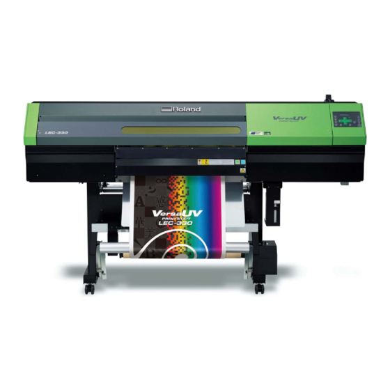
Most of the figures in this document depict the LEC-330.
Advertisement
Table of Contents

Related Manuals for Roland LEC-300A


Summary of Contents for Roland LEC-300A
- Page 1 Roland DG Corp. assumes no responsibility for any direct or indirect loss or damage which may occur with respect to any article made using this product.
-
Page 2: For Canada
You have the right to acquire, modify, and distribute the source code for this GPL/LGPL software. You can obtain the GPL/LGPL source code used in this product by downloading it from the following website. URL: http://www.rolanddg.com/gpl/ Roland DG Corp. has licensed the MMP technology from the TPL Group. -
Page 3: Table Of Contents
Contents To Ensure Safe Use ..................5 Pour utiliser en toute sécurité ..............12 Important Notes on Handling and Use.............20 Printer Unit ....................20 Ink Cartridges ....................21 Chapter 1 Introduction ..................23 1-1 Introduction ...................24 Features of the Machine ......................24 Features of ECO-UV inks .......................24 About This Manual .........................24 Other User's Manuals ........................24 1-2 Part Names and Functions ..............26... - Page 4 Contents 3-2 Using the Media Take-up System ............58 Loading Roll Media ........................58 Removing Taken-up Media ......................62 Chapter 4 Maintenance and Adjustment ............63 4-1 Daily Care and Maintenance ..............64 Disposing of Discharged Ink ......................64 Cleaning .............................66 Care and Maintenance of the Print Heads ................66 4-2 When Head Cleaning Is Not Effective ...........67 Performing More Powerful Cleaning..................67 When Powerful Cleaning Is Not Effective ................69...
- Page 5 Contents Adjusting Head Height to Match Media Thickness ............106 Correcting for Misalignment in Bidirectional Printing ........... 107 Correcting for Misalignment in Bidirectional Printing More Precisely ..... 108 Performing Feed Correction to Alleviate Horizontal Bands and the Like ....111 Performing Distance Correction During Cutting .............
- Page 6 7-3 About the Blade ...................167 7-4 Locations of the Power Rating and Serial Number Labels ....168 7-5 Specifications ..................169 Company names and product names are trademarks or registered trademarks of their respective holders. http://www.rolanddg.com/ Copyright © 2009 Roland DG Corporation...
-
Page 7: To Ensure Safe Use
To Ensure Safe Use Improper handling or operation of this machine may result in injury or damage to prop- erty. Points which must be observed to prevent such injury or damage are described as follows. About WARNING and CAUTION Notices Used for instructions intended to alert the user to the risk of death or WARNING severe injury should the unit be used improperly. - Page 8 To Ensure Safe Use Incorrect operation may cause injury WARNING WARNING Be sure to follow the operation pro- Never attempt to disassemble, repair, cedures described in this documenta- or modify the machine. tion. Never allow anyone unfamiliar Doing so may result in fire, electrical with the usage or handling of the shock, or injury.
- Page 9 Continuing to use the machine may Never place any flammable object result in fire, electrical shock, or injury. nearby. Never use a combustible Contact your authorized Roland DG aerosol spray nearby. Never use in Corp. dealer. any location where gases can ac- cumulate.
- Page 10 To Ensure Safe Use Important notes about the power cord, plug, and electrical outlet Never place any object on top or subject to Never allow to get wet. damage. Never bend or twist with undue force. Never make hot. Never pull with undue force. Dust may cause fire.
- Page 11 To Ensure Safe Use Ink, cleaning fluid, and discharged fluid are flammable and toxic WARNING WARNING Keep open flame away from the work Never drink or sniff ink, cleaning fluid, or discharged fluid, or allow them area. to come in contact with the eyes or Ink and discharged fluid are flam- skin.
- Page 12 To Ensure Safe Use This machine weighs 210 kg (463 lb.). Media weighs 20 kg (44 lb.). WARNING WARNING Install the machine in a location that When storing roll media, implement is level, stable, and able to bear the adequate safety measures to ensure that the stored media will not roll, fall, weight of the machine.
-
Page 13: Warning Labels
To Ensure Safe Use Warning Labels Warning labels are affixed to make areas of danger immediately clear. The meanings of these labels are as follows. Be sure to heed their warnings. Also, never remove the labels or allow them to become obscured. Flammable Ink and discharged fluid are flammable. -
Page 14: Pour Utiliser En Toute Sécurité
Pour utiliser en toute sécurité La manipulation ou l'utilisation inadéquates de cet appareil peuvent causer des blessures ou des dommages matériels. Les précautions à prendre pour prévenir les blessures ou les dommages sont décrites ci-dessous Avis sur les avertissements Utilisé pour avertir l'utilisateur d'un risque de décès ou de blessure ATTENTION grave en cas de mauvaise utilisation de l'appareil. - Page 15 Pour utiliser en toute sécurité L'utilisation incorrecte peut causer des blessures ATTENTION ATTENTION S'assurer de suivre les procédures Débrancher le câble d'alimentation d'utilisation décrites dans la docu- avant de procéder au nettoyage ou à mentation. Ne jamais permettre à l'entretien de l'appareil, et avant d'y quiconque ne connaît pas le fonc- fixer ou d'en retirer des accessoires tionnement ou la manutention de...
- Page 16 Pour utiliser en toute sécurité PRUDENCE PRUDENCE Utiliser l'appareil dans un endroit Ne jamais grimper ni s'appuyer sur propre et bien éclairé. la machine. Travailler dans un endroit sombre ou La machine n'est pas conçue pour sup- encombré peut causer un accident; porter le poids d'une personne.
- Page 17 En outre, prévoir suffisamment d'espace le câble d'alimentation et communiquer pour que la prise électrique soit facile avec le représentant Roland DG Corp. d'accès. autorisé. S'il se produit des étincelles, de la Ne jamais placer d'objet inflam- fumée, une odeur de brûlé, un bruit...
- Page 18 Pour utiliser en toute sécurité Remarques importantes à propos du câble d'alimentation, de la fiche et de la prise électrique Ne jamais déposer aucun objet sur le Ne jamais laisser l'eau toucher le câble, la câble, sur la fiche ou sur la prise car fiche ou la prise.
- Page 19 Pour utiliser en toute sécurité L'encre, les liquides nettoyants et les liquides usées sont inflammables et toxiques ATTENTION ATTENTION Ne pas approcher une flamme nue de Ne jamais boire l'encre, le liquide de l'espace de travail. nettoyage ni les liquides usés, ne L'encre et les liquides usés sont inflam- pas en respirer les vapeurs et ne pas mables.
- Page 20 Pour utiliser en toute sécurité Le poids de cet appareil est de 210 kg (463 lb.) Le poids du support est de 20 kg (44 lb.) ATTENTION ATTENTION Installer l'appareil à un endroit stable S'assurer de verrouiller les roulettes et plat et capable de supporter son de la base.
- Page 21 Pour utiliser en toute sécurité Vignettes d'avertissement Des vignettes d'avertissement sont apposées pour qu'il soit facile de repérer les zones dangereuses. La signification des vignettes est donnée ci-dessous. Respecter les aver- tissements. Ne jamais retirer les vignettes et ne pas les laisser s'encrasser. Inflammable L'encre et les liquides usés sont inflamma- bles.
-
Page 22: Important Notes On Handling And Use
Important Notes on Handling and Use This machine is a precision device. To ensure the full performance of this machine, be sure to observe the following important points. Failure to observe them may not only result in loss of performance, but may also cause malfunction or breakdown. Printer Unit This machine is a precision device. -
Page 23: Ink Cartridges
Ink cartridges come in various types. Use a type that is compatible with the printer. Also, be sure to use only genuine items from Roland DG Corp. Never subject to impact or attempt to disassemble. Never drop or shake forcefully. The impact may rupture the internal pouch and cause the ink to leak. -
Page 25: Chapter 1 Introduction
Chapter 1 Introduction... -
Page 26: Introduction
Features of ECO-UV inks The LEC-300A/330 uses ECO-UV inks. ECO-UV inks are fixed to the media instantly by ultraviolet light. This makes it possible to perform printing on media that is difficult to print using conventional inks. ECO-UV inks are available in a line-up of six colors (cyan, magenta, yellow, black, white, and gloss). - Page 27 1-1 Introduction (2) Roland VersaWorks Quick Start Guide This describes the installation, setup, and basic operation for Roland VersaWorks, the included software raster image processor (RIP). (3) White and Gloss Ink Guide Read this after reading (2). It describes the special methods of creating printing data and performing printing when using white ink or gloss ink.
-
Page 28: Part Names And Functions
1-2 Part Names and Functions Printer Unit Loading lever Front cover Side cover Be sure to close this when You remove this when you You operate this when you you perform printing. perform maintenance. load media. Operation panel You use this to perform various operations. - Page 29 1-2 Part Names and Functions *The figures in this document depict the LEC-330. Cutting carriage Print-head carriage The blade and the separating knife The print heads are inside this. are inside here. UV emitter This is the ultraviolet (UV) LED. It emits light only during printing.
-
Page 30: Operation Panel
1-2 Part Names and Functions Operation Panel Display screen BUSY light BASE POINT key This displays various This lights up during You use this when you setting menus and printing and other such want to set the print- other information. operations. -
Page 31: Media Take-Up System
1-2 Part Names and Functions Media Take-up System AUTO switch MANUAL switch This makes the direction of rota- You use this when you tion for take-up during printing want to operate the media change automatically. take-up system manually. Take-up cable This is connected to the printer. -
Page 33: Chapter 2 Basic Operation
Chapter 2 Basic Operation... -
Page 34: Before Starting Operations
2-1 Before Starting Operations Before Starting the Day's Work The ingredients in white ink tend to settle. Each day, before starting the day's operations, be sure to carry out the following steps. Allowing the ink to stand without carrying out these steps can cause the settled material to harden, resulting in malfunction or other problems. -
Page 35: Switching The Power On And Off
2-2 Switching the Power On and Off Switching the Power On and Off This machine has a main power switch and a sub power switch. Switch on both to use the machine. Whenever printing is finished, switch off the sub power. You also flip down the loading lever to the rear of the machine. -
Page 36: The Power-Saving Feature
2-2 Switching the Power On and Off The Power-saving Feature This machine is provided with a power-saving feature that switches to a low-power "sleep mode" when a fixed interval passes with no operation. The factory default for the time after which the machine switches to the sleep mode is 30 minutes. -
Page 37: Loading And Cutting Off Media
2-3 Loading and Cutting Off Media Loading Media Media may be of one of two types: media wound onto a paper tube (called “roll media”) and media not rolled in this way (called “sheet media”). This section explains how to load media, using roll media as an example. - Page 38 2-3 Loading and Cutting Off Media Attach the media flanges to the roll media. If the inner diameter of the roll-media core measures 3 inches, fit the media flanges onto the core, then turn each knob clockwise all the way to keep the media flanges from falling out. 2 inches 3 inches ...
- Page 39 2-3 Loading and Cutting Off Media Secure the stoppers in place in alignment with the width of the media. Make sure the media flanges are straight. Correct media feed is impossible if either of the media flanges is at an angle. Screws Stoppers Not OK...
- Page 40 2-3 Loading and Cutting Off Media Make sure both edges of the media are above the grit rollers, then place pinch rollers over all grit rollers covered by the media. Placing the pinch rollers inside each of the grit patterns ensures that they are positioned above the grit rollers.
- Page 41 2-3 Loading and Cutting Off Media Secure the media in place so that it is without slack. Hold the media at the center and pull it out, being sure to keep it straight. Make sure all areas of the media are taut. ...
- Page 42 2-3 Loading and Cutting Off Media Clamp the edges of the media with the media clamp. Move the media clamps as shown in the figure below. Left media clamps Right media clamps Line up the edge of the media Line up the edge of the media with the centers of the holes.
- Page 43 2-3 Loading and Cutting Off Media Important Note When Using the Media Clamps Insert the media clamps firmly all the way until they engage with an audible click, and make sure they will not come loose. Incorrect mounting may cause the media to catch or snag and make cor- rect printing impossible, or may lead to malfunction or poor printing quality.
-
Page 44: Cutting Off The Media
2-3 Loading and Cutting Off Media Cutting Off the Media Some media may be thick or may be composed of plastic or other hard material. For such media, never perform cutoff using . Doing so may cause malfunction or other problems. Procedure ... - Page 45 2-3 Loading and Cutting Off Media Some types of media may remain on the platen after cutoff. If the media remains on the platen, remove it by hand. When you cut off media while using the short media clamps, then depending on the media, it may come loose from the media clamps.
-
Page 46: Starting Printing
2-4 Starting Printing Getting Ready to Receive Data from a Computer When you have finished loading media, then follow the steps below. This procedure enables the machine to receive data from the computer and perform output. When printing data that includes cutting paths is received, you can also carry out cutting immediately after performing printing. -
Page 47: Printing Tests And Cleaning
We recommend performing a printing test to check for problems such as dot drop-out before you carry out actual printing. If problems such as dot drop-out are found, clean the print heads. How to Perform a Printing Test Printing test LEC-300A LEC-330 Hold down for one second or longer. - Page 48 Repeat this procedure to display the groups of only the heads that require cleaning. NORMAL CL. LEC-300A : Of groups A or B, cleaning is performed only for the group displayed. LEC-330 : Of groups A through C, cleaning is performed only for the group displayed.
- Page 49 2-4 Starting Printing LEC-330 Press CLEANING... >> Cleaning starts. When it finishes, the screen shown in the figure appears NORMAL CL. again. Press W 736mm Press to go back to the original screen. SETUP SHEET ROLL Perform a printing test again to make sure the dot drop-out has been cor- rected.
-
Page 50: If Ink Runs Out
2-5 If Ink Runs Out Checking for Remaining Ink Procedure Press MENU INK REMAINING Press several times. Press Press W 736mm Press to go back to the original screen. SETUP SHEET ROLL Amount of ink remaining Much Little The display shows an approximate guide to the amount of remaining ink, which may differ somewhat from the actual amount remaining. -
Page 51: If Ink Runs Out
2-5 If Ink Runs Out If Ink Runs Out When ink runs out, a warning beep sounds and printing pauses (unless the default settings have been changed). Pull out the empty ink cartridge and insert a new one. Printing resumes. Important Notes on Replacing Cartridges ... - Page 52 2-5 If Ink Runs Out Pull out the empty ink cartridge and immediately insert the new one. Replace with an item of identi- cal type and color. Keep the labeled side face up. Insert and remove slowly, one at a time. ...
-
Page 53: Performing Cutting
2-6 Performing Cutting To Perform Cutting To perform cutting, carry out the procedure described below. Move the media clamps to locations where they don’t clamp the media. Alter- natively, remove the media clamps. Media clamps When you're performing cutting only, then if you're cutting roll media, allow the media to hang down from the rear of the machine. -
Page 54: Performing A Cutting Test
2-6 Performing Cutting Hints and Tips for Cutting Setting the [PREFEED] menu item to “ENABLE” makes the machine automatically feed out media and take it up again before cutting. This makes it unnecessary to run out media to the rear of the machine before the operation. ... -
Page 55: Making The Setting For Blade Force
2-6 Performing Cutting Making the Setting for Blade Force Procedure Press FORCE 50gf 60gf to enter the value. Press to finish making the setting, and go W 736mm back to the original screen. SETUP SHEET ROLL Pressing enters the cutting configuration menu. You can also make the settings for other cut- ting conditions in addition to the blade force. -
Page 57: Chapter 3 Operation Of The Media Take-Up System
Chapter 3 Operation of the Me- dia Take-up System... -
Page 58: The Media Take-Up System
3-1 The Media Take-up System Features of the Media Take-up System Using the media take-up system lets you perform printing while the media is taken up automatically. This makes possible unattended operation at night and efficient printing of lengthy media. Operating Conditions for the Media Take-up System Never Use When Performing Cutting Never use the media take-up system when you're performing cutting operations. -
Page 59: About The Paper Tube
To purchase a replacement, contact your authorized Roland DG Corp. dealer or Roland DG Corp. Chapter 3 Operation of the Media Take-up System... -
Page 60: Using The Media Take-Up System
3-2 Using the Media Take-up System Loading Roll Media Pass the media through the printer. Move the dancer roller toward the rear. Dancer roller Load the roll media. P.35, "Loading Media" Pull back the loading lever. The media is secured in place. - Page 61 3-2 Using the Media Take-up System Press to adjust the length of the media to be pulled out. You can adjust the length of the media in 10-millimeter steps by pressing To pull out media continuously, hold down Fasten the media in place with tape at three locations (the center and both edges) so that the media is not at an angle.
- Page 62 3-2 Using the Media Take-up System Make the setting for the direction of automatic take-up and perform take-up of the media onto the paper tube. Press The media is pulled out and the screen shown in the figure appears. ...
- Page 63 3-2 Using the Media Take-up System ■ Take-up with inward curl Ensure there is no slack. Press W 736mm Making the setting is complete when the screen shown in the figure (the top menu) appears. When you begin take-up, take care to ensure that the end of the media does not become rolled or creased.
-
Page 64: Removing Taken-Up Media
3-2 Using the Media Take-up System Removing Taken-up Media CAUTION Removal of taken-up roll media from the unit is a task which must be carried out by two or more persons. If dropped, such items may cause injury. Cut off the media. ... -
Page 65: Chapter 4 Maintenance And Adjustment
Chapter 4 Maintenance and Adjustment... -
Page 66: Daily Care And Maintenance
4-1 Daily Care and Maintenance Disposing of Discharged Ink The drain bottle collects discharged fluid. Dispose of collected material before the bottle becomes full. The message shown in the figure appears when a certain amount of discharged fluid has collected in the bottle. - Page 67 4-1 Dairy Care and Maintenance Attach the emptied bottle and reset the discharged-fluid count. Attach the emptied bottle. Press RESET DRAIN COUNTER Press a second time. MAINTENANCE DRAIN BOTTLE Press W 736mm Press to go back to the original screen. SETUP SHEET ROLL WARNING...
-
Page 68: Cleaning
P. 70, "Cleaning Using the Cleaning Kit" Note: The print heads are components that wear out. Periodic replacement is required, with the frequency of replacement depending on use. Purchase them from your autho- rized Roland DG Corp. dealer. Chapter 4 Maintenance and Adjustment... -
Page 69: When Head Cleaning Is Not Effective
Repeat this procedure to display the groups of only MEDIUM CL. the heads that require cleaning. LEC-300A : Of groups A or B, cleaning is performed only for the group displayed. LEC-330 : Of groups A through C, cleaning is performed only for the group displayed. - Page 70 We recommend performing the printing test on transparent or silver-colored media. Start cleaning. Press If You Chose "MEDIUM CL." LEC-300A CLEANING... The screen shown in the figure appears, then cleaning starts. >> When it finishes, the screen shown in the figure appears. Go ...
-
Page 71: When Powerful Cleaning Is Not Effective
4-2 When Head Cleaning Is Not Effective Press W 736mm Press to go back to the original screen. SETUP SHEET ROLL When Powerful Cleaning Is Not Effective If problems such as dot drop-out persist even after you have performed powerful cleaning several times, then use the cleaning kit to clean the heads. -
Page 72: Cleaning Using The Cleaning Kit
When Hardening of the Ink on Printed Material Is Insufficient Clean the UV emitter using the cleaning kit. If you use up the cleaning kit, purchase a new one from your authorized Roland DG Corp. dealer. The print heads are components that wear out. Periodic replacement is required, with the frequency of replacement depending on use. - Page 73 4-3 Cleaning Using the Cleaning Kit Change to the print-head manual-cleaning mode. Remove any media. Press MENU SUB MENU Press several times. Press SUB MENU MAINTENANCE Press Press MAINTENANCE CLEANING Press OPEN MAINTE- NANCE COVER Open the front cover and remove the maintenance cover.
- Page 74 4-3 Cleaning Using the Cleaning Kit Touch the location shown in the figure to discharge any static electricity. Preparations are complete when this screen ap- FINISHED? pears. Clean using the cleaning stick. Be especially careful to clean away any fibrous dust (lint). ...
- Page 75 4-3 Cleaning Using the Cleaning Kit Perform cleaning in the sequence shown in the figure below. Never rub the nozzle surface of the head. Gently stroke the sponge. Clean only the metal frame. Never rub with force. Area to clean Area to clean *While working with the cleaning swab, be careful not to touch the print head surfaces directly.
- Page 76 4-3 Cleaning Using the Cleaning Kit Clean the locations shown in the figure. *The figures in this document depict the LEC-330. Area to clean Area to clean Quit the manual cleaning mode. Press CLOSE SIDE COVER The screen shown in the figure appears. ...
- Page 77 4-3 Cleaning Using the Cleaning Kit Open the front cover and attach the maintenance cover. Screws Screws Maintenance cover. Close the front cover. MAINTENANCE CLEANING Press Press W 736mm Press to go back to the original screen. SETUP SHEET ROLL Perform a printing test to verify the results of the procedure.
-
Page 78: Replacing Consumable Parts
4-4 Replacing Consumable Parts Replacing the Wipers The wipers are components that you use when TIME FOR WIPER REPLACE cleaning the print heads. When the screen displays a message like the one shown, it means the item Press needs to be replaced. Replace with new items. CAUTION Be sure to perform operations as specified by these instructions, and never touch any area not specified in the instructions. - Page 79 4-4 Replacing Consumable Parts Touch the location shown in the figure to discharge any static electricity. Preparations are complete when this screen ap- FINISHED? pears. Replace the wipers. Use the included tweezers. Detach the old wipers. Detach the hook and pull up and out. ...
- Page 80 4-4 Replacing Consumable Parts Attach the hook. Hook Quit the [REPLACE WIPER] menu. Press CLOSE SIDE COVER Attach the side cover. Screws Side cover Hook Screws Press CLEANING... >> After the process to quit the wiper replacement mode, the screen shown in the figure appears.
-
Page 81: Replacing The Blade
4-4 Replacing Consumable Parts Replacing the Blade If the blade becomes dull, replace it with the included replacement blade. CAUTION Be sure to perform operations as specified by these instructions, and never touch any area not specified in the instructions. Sudden movement of the machine may cause injury. - Page 82 4-4 Replacing Consumable Parts Replace the blade. Remove the blade holder. Remove the old blade. Press this pin Blade holder Old blade Install a new blade. Blade holder New blade Reinstall the blade holder. If installed without supporting the screw Insert until in this way, cutting quality may become the collar is...
-
Page 83: Replacing The Separating Knife
4-4 Replacing Consumable Parts Tighten the screw. Tug the blade holder upward to make sure it does not come loose. Quit the blade replacement mode. Close the front cover. MAINTENANCE REPLACE KNIFE Press Press W 736mm Press to go back to the original screen. - Page 84 4-4 Replacing Consumable Parts Press MAINTENANCE REPLACE KNIFE Press several times. Press NOW PROCESSING.. The cutting carriage moves to a location where blade replace- ment is possible, and then the screen shown in the figure OPEN FRONT appears. COVER ...
- Page 85 4-4 Replacing Consumable Parts Tighten the screw. Take care to ensure that the knife does not slip out of position at this time. Quit the blade replacement mode. Close the front cover. MAINTENANCE REPLACE KNIFE Press Press W 736mm Press to go back to the original screen.
-
Page 86: Adjustment Of White Ink
4-5 Adjustment of White Ink When white ink is used, dot drop-out or other problems that impede normal ink discharge may occur even when powerful cleaning or manual cleaning of the print heads has been performed. This can occur because the ingredients in white ink tend to settle, and may harden if allowed to stand for a lengthy time. - Page 87 4-5 Adjustment of White Ink Press W 736mm Press to go back to the original screen. SETUP SHEET ROLL Chapter 4 Maintenance and Adjustment...
-
Page 88: When Not In Use For A Prolonged Period
4-6 When Not in Use for a Prolonged Period Keep Performing Maintenance Switch on the power once every two weeks. Switch on the sub power once every two weeks. When you turn on the power, the machine automati- cally performs some operations such as those to keep the print heads from drying out. Allowing the machine to stand completely unused for a prolonged period may damage the print heads, so be sure to switch on the power to perform these automatic operations. -
Page 89: When Moving The Unit
4-7 When Moving the Unit Procedures from Preparing to Move Through Reinstalling To move the machine, you must completely drain all ink inside the machine and secure the print heads in place with packing materials to protect them. Attempting to move the machine without first doing this may result in damage to internal components due to leaking ink or damage to the heads. - Page 90 4-7 When Moving the Unit Secure the print heads in place. Remove the drain bottle and detach the drain-bottle stand. Then attach the drain-tube cover. Detach the blade holder. Raise the loading lever. Secure the print heads in place using the packing material. ...
-
Page 91: Chapter 5 Feature Reference
Chapter 5 Feature Reference... -
Page 92: Pausing Or Canceling Output
5-1 Pausing or Canceling Output Canceling Output Before It Finishes Procedure Press Hold down for one second or longer. Stop sending output data from the computer. Description pauses output. Pressing a second time here resumes printing, but a horizontal stripe is produced at the location where printing was stopped. -
Page 93: Setting The Print-Start Position
5-2 Setting the Print-start Position Setting the Print-start Position Procedure to move the cutting carriage. Align the center of the blade with the new print-start position. Printing area Print-start position Feed-direction Scan-direction start position start position Press W 600mm This indicates that the printing-start position has been set. - Page 94 5-2 Setting the Print-start Position possible width at the position. This feature is also available when you're printing or cutting various test patterns, and can help you use media with less waste. Note, however, that the left and right positions are not restored to their defaults for test patterns.
-
Page 95: Accommodating Various Kinds Of Media
5-3 Accommodating Various Kinds of Media Using Transparent Media Procedure Press MENU MENU SUB MENU SUB MENU Press several times. Press twice. EDGE DETECTION ENABLE DISABLE to select "DISABLE." Press to enable the setting. The settings are changed and the screen shown in the figure appears. -
Page 96: Speeding Up Printing For Narrow Media
5-3 Accommodating Various Kinds of Media Press W 736mm Press to go back to the original screen. SETUP SHEET ROLL Description The platen uses suction to grip the media and keep it stable. When media comes loose from the platen because it is warped or wrinkled, increasing the suction force may help correct the problem. -
Page 97: Preventing Soiling Of The Media And Dot Drop-Out During Printing
5-3 Accommodating Various Kinds of Media minimum amount necessary, and this can be expected to yield the fastest printing. Note, however, that the range of print-head movement is limited to the maximum scanning width that is printed. Also, the maximum scanning width printed is reset every time printing of a page finishes. Range of print-head movement when set to "OFF"... -
Page 98: Printing Media That Warps Easily
5-3 Accommodating Various Kinds of Media Press W 736mm Press to go back to the original screen. SETUP SHEET ROLL Description Ink tends to collect on the surface of the heads when you use media prone to buildup of static charge, when the ambient temperature is low, or when the head height is set to “HIGH. -
Page 99: Default Setting
5-3 Accommodating Various Kinds of Media Replace the short media clamps with the long ones. Remove the short media clamps. Pull back while hold- Push here. ing down the area. Attach the long media clamps. Insert until it clicks into place. -
Page 100: How To Load Sheet Media
5-3 Accommodating Various Kinds of Media How to Load Sheet Media To load and use sheet media, follow the steps below. Load the sheet media. Measure the thickness of the sheet media. If the measured value is 0.5 millimeters or more, increase the height of the print heads. ... - Page 101 5-3 Accommodating Various Kinds of Media Open the front cover. Align the end of the sheet media with the location shown in the figure. Sheet media Align here Pull back the loading lever. The sheet media is secured in place. Loading lever ...
- Page 102 5-3 Accommodating Various Kinds of Media Make sure that media feed is stable. If any of the situations described below takes place, problems such as the print heads striking the sheet media may occur, resulting in malfunction or the like. Reload the sheet media. If the problem persists, the sheet media cannot be used.
- Page 103 5-3 Accommodating Various Kinds of Media Press and hold Hold down until the print-end position reaches the platen. For media that passes through the media discharge port of ①, be sure to comply with the following. Otherwise problems such as the print heads striking the sheet media may occur, resulting in malfunction or the like.
-
Page 104: Changing How The Printer Operates
5-4 Changing How the Printer Operates Executing Environment Matching Automatically Procedure Press MENU CUTTING MENU Press several times. Press CUTTING MENU AUTO ENV. MATCH Press Press AUTO ENV. MATCH DISABLE ENABLE to select "ENABLE." Press to enable the setting. ... -
Page 105: Setting The Interval Until Activation Of The Sleep Mode
5-4 Changing How the Printer Operates Press W 736mm Press to go back to the original screen. SETUP SHEET ROLL Description This lets you change, according to your purpose, the operation that takes place when an ink cartridge is empty. "STOP"... -
Page 106: Deactivating The Sleep Mode
5-4 Changing How the Printer Operates Deactivating the Sleep Mode Procedure Press MENU SUB MENU Press several times. Press SUB MENU SLEEP Press several times. Press SLEEP SETTING Press Press SETTING ENABLE DISABLE to select "DISABLE." Press to enable the setting. -
Page 107: Returning All Settings To Their Initial Values
5-4 Changing How the Printer Operates Description This sets the language and units of measurement displayed on the printer's screen. Default Setting [MENU LANGUAGE]: ENGLISH [LENGTH UNIT]: mm [TEMP. UNIT]: ˚C Returning All Settings to Their Initial Values Procedure Press MENU SUB MENU... -
Page 108: Optimizing Printing To Match Media Thickness
5-5 Optimizing Printing to Match Media Thickness Adjusting Head Height to Match Media Thickness Procedure Press MENU HEAD HEIGHT Press several times. Press HEAD HEIGHT Open the front cover. Move the lever to adjust the height of the head. Moving the lever to "HIGH"... -
Page 109: Correcting For Misalignment In Bidirectional Printing
5-5 Optimizing Printing to Match Media Thickness in Bidirectional Printing," p. 108, "Correcting for Misalignment in Bidirectional Printing More Precisely" Default Setting [HEAD HEIGHT]: LOW Correcting for Misalignment in Bidirectional Printing Procedure Print a test pattern. Press MENU ADJUST BI-DIR Press ... -
Page 110: Correcting For Misalignment In Bidirectional Printing More Precisely
5-5 Optimizing Printing to Match Media Thickness Go back to the original screen. Press W 736mm Press to go back to the original screen. SETUP SHEET ROLL Description The bidirectional-printing mode (in which the heads perform printing during both their outbound pass and return pass) offers the advantage of being able to shorten printing times, but subtle misalignment occurs during the outbound and return passes. - Page 111 We recommend performing the printing test on transparent or silver-colored media. Enter the correction values that you read. Enter the corresponding correction values for H1 through H6 (H1 through H3 on LEC-300A). Press DETAIL SETTING SETTING NO.1...
- Page 112 5-5 Optimizing Printing to Match Media Thickness Press DETAIL SETTING SETTING NO.2 Press to select. Use set the correction value. Only LEC-330 Press to finish making the settings for [SET- TING NO.2]. Press DETAIL SETTING SETTING NO.3 ...
-
Page 113: Performing Feed Correction To Alleviate Horizontal Bands And The Like
5-5 Optimizing Printing to Match Media Thickness Performing Feed Correction to Alleviate Horizontal Bands and the Like Procedure Print a test pattern. Press MENU CALIBRATION Press several times. Press CALIBRATION TEST PRINT Press to start printing. Read the correction values from the test pattern. In the printing example shown below, "-0.40"... - Page 114 5-5 Optimizing Printing to Match Media Thickness Description The movement distance of media experiences subtle changes due to the thickness of the media . When the movement distance becomes discrepant, horizontal stripes are more likely to occur during print- ing. We recommend performing correction to match the media you're using. Also, perform the actual printing in an operating environment identical to that used for the test pattern.
-
Page 115: Performing Distance Correction During Cutting
5-5 Optimizing Printing to Match Media Thickness Performing Distance Correction During Cutting Procedure Press MENU CUTTING MENU Press several times. Press CUTTING MENU CALIBRATION Press twice. Press twice. FEED SETTING 0.00% 0.00% to make the setting for the cor- rection value. -
Page 116: Making Various Adjustments For Cutting
5-6 Making Various Adjustments for Cutting Making the Cutting Conditions Set on the Machine Take Precedence Procedure Press MENU CUTTING MENU Press several times. Press CUTTING MENU CUTTING PRIOR Press several times. Press CUTTING PRIOR COMMAND MENU to select "MENU."... - Page 117 5-6 Making Various Adjustments for Cutting Description This enables you to check and verify the settings for the cutting conditions using cutting-test results. P. 52, "Performing a Cutting Test" [FORCE]: This sets the force (pressure) of the blade. [SPEED]: This sets the speed of cutting. [OFFSET]: This makes the blade-offset setting for the blade.
-
Page 118: Adjusting The Cutting-In Amount
5-6 Making Various Adjustments for Cutting Adjusting the Cutting-in Amount When you want to perform accurate and fine Min. 0 mm Max. 2.5 mm adjustment of the cutting-in amount, such as when cutting media with thin carrier paper, you can obtain good results by adjusting the tip of the Amount blade. - Page 119 5-6 Making Various Adjustments for Cutting to move the cutting carriage. You can perform cutting-test printing at any location you want. Print-start position Scan-direction Feed-direction start location start location Press Execute the [CUT TEST PRINT] menu item. Press MENU CUT TEST PRINT...
- Page 120 5-6 Making Various Adjustments for Cutting Check the results of the cutting test and make adjustments. Open the front cover. Check the results of the cutting test and make adjustments. P. 114, "Fine-tuning the Cutting Conditions," p. 116, "Adjusting the Cutting-in Amount" ...
-
Page 121: Preventing Pulling Of The Media With Undue Force When Performing Cutting Only
5-6 Making Various Adjustments for Cutting Description Hardened ink is thick. This means that the cutting conditions when you're cutting a printed surface are different from the cutting conditions when you're cutting a surface that hasn't been printed. When you're cutting a printed surface, use this [CUT TEST PRINT] to adjust the cutting conditions. Note: These adjustments are general suggestions. -
Page 122: Correcting Misalignment Of The Printing And Cutting Positions
5-6 Making Various Adjustments for Cutting Correcting Misalignment of the Printing and Cutting Positions Procedure Check the setting for the [AUTO ENV. MATCH] menu item. Make sure the [AUTO ENV. MATCH] menu item is set to "ENABLE." P. 102, "Executing Environment Matching Automatically" Execute the [ADJUST BI-DIR] menu item. - Page 123 5-6 Making Various Adjustments for Cutting Print and cut a test pattern for setting the correction values. Press PRINT - CUT ADJ. TEST PRINT 2 Press to execute From the test pattern, read the value at the location. Test pattern Cutting line Check the value on the [SCAN] side.
- Page 124 5-6 Making Various Adjustments for Cutting Check the results of adjustment. Press PRINT - CUT ADJ. TEST PRINT Press to execute. If the printing and cutting lines are aligned, adjustment is complete. If further adjustment is needed, go back to step and fine- tune the adjustment.
-
Page 125: Performing Printing And Cutting Separately
5-7 Performing Printing and Cutting Separately To Perform Printing and Cutting Separately When you remove printed media and then reload it and perform cutting, you carry out alignment to prevent misalignment of the printing results and the cut lines. You do this at times such as when, for example, you perform lamination or other processing after printing, then reload the media and perform cutting. -
Page 126: Aligning Automatically And Cutting
5-7 Performing Printing and Cutting Separately Aligning Automatically and Cutting When you make the setting for reading crop marks when sending cutting data from the computer, alignment is performed with the presence or absence of crop marks determined automatically. For in- formation on how to make the setting, refer to the documentation for the software RIP you're using. -
Page 127: Aligning Manually And Cutting
5-7 Performing Printing and Cutting Separately If this does not resolve the problem, then perform alignment manually. P. 125, "Aligning Manually and Cutting" If the crop marks cannot be detected easily because of the effects of media warping or the like, then perform alignment manually. -
Page 128: Correcting Misalignment For Printing And Cutting When Using Crop Marks
5-7 Performing Printing and Cutting Separately Set the align points. to align the center of the blade with the loca- tion shown in the figure. Hold down for one second or longer. SETTING ALIGN POINT 1 The number of the align point you set is automatically deter- mined. - Page 129 5-7 Performing Printing and Cutting Separately Execute the [ADJUST BI-DIR] menu item. Load the media. P. 35, "Loading Media," p. 98, "How to Load Sheet Media" Perform bidirectional adjustment. P. 107, "Correcting for Misalignment in Bidirectional Printing," p. 108, "Correcting for Misalignment in Bidi- rectional Printing More Precisely"...
- Page 130 5-7 Performing Printing and Cutting Separately From the test pattern, read the correction value at the location. Test pattern Check the value on Cutting line the [SCAN] side. Correction-value scale Check the value on Scan direction the [FEED] side. The point where the cutting line intersects the correction-value scale is the correction value.
- Page 131 5-7 Performing Printing and Cutting Separately Description Depending on the composition of the media, the positioning of printing and cutting may be misaligned even when you're using crop marks. Make corrections for misaligned printing and cutting for the media you're using. Default Setting [F] (feed direction): 0.00 mm [S] (scanning direction): 0.00 mm...
-
Page 132: Installation Environment
5-8 Gloss Ink Features and Printing Methods Features of Gloss Ink The ECO-UV Gloss ink that this unit uses can impart a glossy feel to the printed item, as well as enhanc- ing weatherability and robustness*. Also, depending on the printing settings, you can even deliberately eliminate glossiness and produce a matte finish, or perform fill overprinting using gloss ink to raise the printed surface and create an embossed finish. -
Page 133: White Ink Features And Printing Methods
5-9 White Ink Features and Printing Methods Features of White Ink The ECO-UV white ink that this unit uses achieves high density and concealment, and is capable of providing attractive results when white and CMYK inks are overprinted. This ink is suited to printing on transparent media, and lets you create results intended to be viewed from the back (the side opposite the printed surface) by reversing the image and changing the sequence in which the white ink and CMYK inks are printed. -
Page 134: Saving The Printer Settings To Match The Media
5-10 Saving the Printer Settings to Match the Media Saving Optimized Media Settings As Preset Values Procedure Press MENU PRESET Press Press Press to select any one from "NAME1" to "NAME8." Press to save. The present menu settings are saved in the preset you chose ... -
Page 135: Loading A Saved Preset
5-10 Saving the Printer Settings to Match the Media [PRINT-CUT ADJ.] P. 120, "Correcting Misalignment of the Printing and Cutting Positions" [CROP-CUT ADJ.] P. 126, "Correcting Misalignment for Printing and Cut- ting When Using Crop Marks" Up to eight types of presets can be saved. You can assign a name to each one. Using media names for these may aid recognition and clarity. - Page 136 5-10 Saving the Printer Settings to Match the Media Press NAME to enter a character. Press NAME SAMPLE_ to enter the next character. Enter the following characters in the same way. When you're finished entering text, press Press W 736mm Press...
-
Page 137: Making The Network Settings
5-11 Making the Network Settings Setting the IP Address, Subnet Mask, Etc. Procedure Press MENU SYSTEM INFO. Press several times. Press SYSTEM INFO. NETWORK Press Press NETWORK IP ADDRESS to choose the item whose setting you want to make. ... -
Page 138: Viewing Information About The Media And The System
5-12 Viewing Information about the Media and the System Displaying the Amount of Media Remaining Procedure Press MENU SHEET REMAIN Press several times. Press SHEET REMAIN SET LENGTH Press Press SET LENGTH 0.0 m to set the amount of media re- 25.0 m maining. -
Page 139: Verifying The Setting For The Amount Remaining Every Time The Media Is Changed
5-12 Viewing Information about the Media and the System Verifying the Setting for the Amount Remaining Every Time the Media Is Changed Procedure Press MENU SHEET REMAIN Press several times. Press SHHET REMAIN AUTO DISPLAY Press twice. Press AUTO DISPLAY DISABLE... -
Page 140: Printing The Amount Of Remaining Media
5-12 Viewing Information about the Media and the System Printing the Amount of Remaining Media Procedure Press MENU SHEET REMAIN Press several times. Press SHHET REMAIN PRINT MEMO Press to perform printing. Press W 736 mm L 25.0 m Press to go back to the original screen. -
Page 141: Viewing The Serial Number, Firmware Version, And Other Information
5-12 Viewing Information about the Media and the System Viewing the Serial Number, Firmware Version, and Other Information Procedure Press MENU SYSTEM INFO. Press several times. Press SYSTEM INFO. SERIAL NO. to choose the information you want to view. ... -
Page 142: Viewing The Network Settings
5-12 Viewing Information about the Media and the System Viewing the Network Settings Procedure Press MENU SYSTEM INFO. Press several times. Press SYSTEM INFO. NETWORK Press Press NETWORK IP ADDRESS to choose the information you want to view. ... -
Page 143: Performing Maintenance
5-13 Performing Maintenance Draining Ink and Performing Internal Washing Procedure Press MENU SUB MENU Press several times. Press SUB MENU INK CONTROL Press twice. Press INK CONTROL HEAD WASH Press twice. Press to execute. Description This drains the ink inside the printer and washes the interior using cleaning SOL INK cartridges as a preliminary procedure for moving the printer or conducting maintenance. -
Page 144: Menu List
5-14 Menu List Main Menu Press To the [CUT TEST PRINT] menu To the [NAME8] menu To the [NAME] menu MENU PRESET LOAD PRESET LOAD NAME1 LOAD NAME2 LOAD NAME3 LOAD NAME4 LOAD NAME5 LOAD NAME6 LOAD NAME7 LOAD NAME8 To the [NAME1] menu To the [NAME8] menu PRESET... - Page 145 5-14 Menu List Continued Continued Continued To the [NAME8] menu PRESET NAME NAME NAME NAME1 To the [LOAD] menu NAME NAME NAME2 NAME NAME NAME3 NAME NAME NAME4 NAME NAME NAME5 NAME NAME NAME6 NAME NAME NAME7 NAME NAME NAME8 To the [NAME1] menu To the [DETAIL SETTING] menu MENU...
- Page 146 5-14 Menu List Continued MENU HEAD HEIGHT HEAD HEIGHT To the [MAINTENANCE] menu MENU SUB MENU EDGE DETECTION SUB MENU EDGE DETECTION ENABLE ENABLE SUB MENU VACUUM POWER. VACUUM POWER AUTO AUTO SUB MENU FULL WIDTH S FULL WIDTH S FULL FULL SUB MENU...
- Page 147 5-14 Menu List Continued To the [NETWORK] menu MODEL MODEL MENU SYSTEM INFO . LEC-330 LEC-300A SYSTEM INFO . MODEL SYSTEM INFO . SERIAL NO . SERIAL NO . ZS00001 SYSTEM INFO . ECO-UV C M Y K Gl W SYSTEM INFO .
- Page 148 5-14 Menu List Continued To the [TEST PRINT 2] menu To the [AUTO ENV. MATCH] menu MENU CUTTING MENU PRINT-CUT ADJ. CUTTING MENU PRINT-CUT ADJ. TEST PRINT (*1) PRINT-CUT ADJ. SETTING PRINT-CUT ADJ. TEST PRINT 2 To the [TEST PRINT] menu To the [TEST PRINT 2] menu CUTTING MENU CROP-CUT ADJ.
-
Page 149: Language And Unit Menu
5-14 Menu List Language and Unit Menu Hold down and switch on the sub power. MENU LANGUAGE ENGLISH LENGTH UNIT TEMP UNIT Cleaning Menu Press To the [POWERFUL CL.] menu NORMAL CL. NORMAL CL. CLEANING NORMAL CL. MEDIUM CL. MEDIUM CL. CLEANING MEDIUM CL. -
Page 150: Cutting Configuration Menu
5-14 Menu List Cutting Configuration Menu Press FORCE SPEED OFFSET UP SPEED 50 gf 50 gf 30 cm/s 30 cm/s 0.250 mm 0.250 mm 30 cm/s 30cm/s Chapter 5 Feature Reference... -
Page 151: Chapter 6 What To Do If
Chapter 6 What to Do If... -
Page 152: The Machine Doesn't Run
6-1 The Machine Doesn't Run lighted, it means that a correct connection to the The Printer Unit Doesn't Run network has not been made. Make sure the network Is the power switched on? routing is suitable. Try connecting the computer and Switch on the printer's main power, then press the the machine to the same hub, or connecting them sub power switch and make sure the sub power... -
Page 153: Attractive Printing Is Impossible
6-2 Attractive Printing Is Impossible Printed Results Are Coarse or Contain Horizontal Stripes When you are performing bidirectional printing, use the [ADJUST BI-DIR] menu item to carry out Do the print heads show dot drop-out? correction. The optimal adjustment value may vary, Carry out a printing test and make sure no dot drop- depending mainly on the thickness of the media. -
Page 154: Colors Are Unstable Or Uneven
6-2 Attractive Printing Is Impossible wind or blown air. These factors may lead to missing P. 132, "Saving Optimized Media Settings As Preset dots or reduced printing quality. Values" P. 133, "Loading a Saved Preset" Is the printer being used in a location sub- ject to severe changes in the operating environment? Colors Are Unstable or Uneven... -
Page 155: Cutting Is Misaligned Or Skewed
6-2 Attractive Printing Is Impossible Setting [AUTO ENV. MATCH] to "ENABLE" performs Perform cleaning periodically. matching to the environment to correct for mis- P. 66, "Cleaning" alignment. P. 102, "Executing Environment Matching Automati- Cutting Is Misaligned or Skewed cally"... -
Page 156: The Media Jams
6-3 The Media Jams The Media Jams If an error message is displayed because the media has jammed, immediately correct the problem. Failure to do so may damage the print heads. P. 161, [MOTOR ERROR TURN POWER OFF] Is the media warped or wrinkled? Many factors can cause warping or wrinkling. -
Page 157: The Media Cannot Be Taken Up Smoothly
6-4 The Media Cannot Be Taken Up Smoothly The Media Cannot Be Taken Up Smoothly Is media feed unstable? Various factors can make media feed unstable. Refer to the following and correct the problem. P. 156, "Media Wrinkles or Shrinks, or Feed Is Unstable" Is the paper tube installed correctly? Securely insert the paper tube onto the end caps. -
Page 158: Media Wrinkles Or Shrinks, Or Feed Is Unstable
6-5 Media Wrinkles or Shrinks, or Feed Is Unstable A variety of problems can occur if the media feed is not smooth. This can cause such problems as poor printing quality, contact with the media by the print heads, misaligned positioning, or media jams. -
Page 159: The Print Heads Stopped Moving
If the Heads Still Do Not Move If the heads still do not move, carry out the following emergency response measure, then contact your authorized Roland DG Corp. dealer. 1. Switch off the main power. 2. Open the front cover. -
Page 160: If A Message Appears
6-7 If a Message Appears [INSTALL DRAIN BOTTLE] These are the main messages that appear on the machine's display to prompt correct op- Check whether the drain bottle is installed. Install the eration. They do not indicate any error. Follow drain bottle, then press the prompts and take action accordingly. -
Page 161: If An Error Message Appears
After you switch off the power, inform your send the data again. authorized Roland DG Corp. dealer of the number that appeared on the display. The size of the data being output is too small. - Page 162 6-8 If an Error Message Appears can operate. [SHEET TOO SMALL CONTINUE?] Operation cannot be continued. Switch off the sub The size of the data is larger than the print- power. The displayed temperature is the current ing or cutting area of the loaded media. ambient temperature of the installation location.
- Page 163 Switch off the sub power. After you switch off the This error may be caused by such factors as a mistake power, inform your authorized Roland DG Corp. in loading the media, a media jam, or an operation dealer.
-
Page 165: Chapter 7 Specifications
Chapter 7 Specifications... -
Page 166: Usable Media
7-1 Usable Media Conditions for Usable Media Media width 182 to 762 mm (7.2 to 30 inches) A) Cuttable media thickness 0.08 to 0.22 mm (3.2 to 8.6 mil) (depending on media composition) B) Maximum media thickness (including backing paper) Printing only: 1.0 mm (39 mil) When performing cutting: 0.4 mm (15 mil) C) Roll outer diameter... -
Page 167: Printing Or Cutting Area
7-2 Printing or Cutting Area Maximum Area The printing or cutting area along the horizontal plane (the direction in which the carriage moves) is determined by the position of the pinch rollers. 210mm Max. 736 mm (29 in.) (8.3 in.) Media Max. -
Page 168: Media-Cutoff Location During Continuous Printing
7-2 Printing/Cutting Area Media-cutoff Location During Continuous Printing When a media-cutoff command is sent from the computer, the cutoff location on the media is as shown in the figure below. Second page 75mm (3 in.) Location where separated Margin (setting on the computer) First page Chapter 7 Specifications... -
Page 169: About The Blade
7-3 About the Blade The cutting conditions and the service life of the blade change according to the media and the operat- ing environment, even when using identical blades. The service life also differs according to the type of blade. A rough guide is shown below. Amount of Blade life* Blade... -
Page 170: Locations Of The Power Rating And Serial Number Labels
7-4 Locations of the Power Rating and Serial Number Labels Serial Number This is required when you seek maintenance, servicing, or support. Never peel off the label or let it get dirty. Power Rating Use an electrical outlet that meets the requirements for voltage, frequency, and amperage given here. -
Page 171: Specifications
AC 100 to 240 V ±10%, 4.2A, 50/60 Hz P o w e r c o n - During operation Approx. 370 W sumption LEC-300A : 14.4 W Sleep mode LEC-330 : 15.3 W Acoustic noise During operation 64 dB (A) or less... - Page 172 Exclusive stands, power cord, blade, blade holder (XD-CH2), media clamps, replacement blade for separating knife, clean- ing kit, software RIP (Roland VersaWorks) , User's Manual, etc. The length of printing or cutting is subject to the limitations of the program.
- Page 180 R1-091026...
Need help?
Do you have a question about the LEC-300A and is the answer not in the manual?
Questions and answers