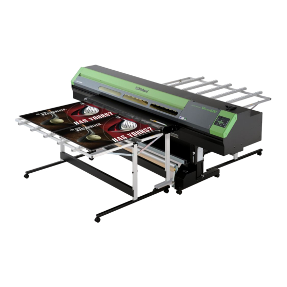
Roland VersaUV LEJ-640 Setup Manual
Hide thumbs
Also See for VersaUV LEJ-640:
- User manual (176 pages) ,
- Supplement manual (24 pages) ,
- Service notes (321 pages)

Related Manuals for Roland VersaUV LEJ-640


Summary of Contents for Roland VersaUV LEJ-640
- Page 1 Setup Guide Read this first. This describes the setup tasks and important conditions about the installation location that must be met in order to enable use of this machine.
- Page 2 Roland DG Corp. assumes no responsibility for any direct or indirect loss or damage which may occur through use of this product, regardless of any failure to perform on the part of this product.
-
Page 3: Table Of Contents
Important Note on Draining Ink ....................60 9. When Moving the Unit ................61 Procedures from Preparing to Move Through Reinstalling ..........61 Company names and product names are trademarks or registered trademarks of their respective holders. http://www.rolanddg.com/ Copyright © 2011-2016 Roland DG Corporation... -
Page 4: To Ensure Safe Use
To Ensure Safe Use Improper handling or operation of this machine may result in injury or damage to property. Points which must be observed to prevent such injury or damage are described as follows. About WARNING and CAUTION Notices Used for instructions intended to alert the user to the risk of death or WARNING severe injury should the unit be used improperly. - Page 5 To Ensure Safe Use Incorrect operation may cause injury WARNING WARNING Be sure to follow the operation proce- Never attempt to disassemble, repair, or dures described in this documentation. modify the machine. Never allow anyone unfamiliar with the Doing so may result in fire, electrical shock, usage or handling of the machine to or injury.
- Page 6 Never your authorized Roland DG Corp. dealer. use if any component is damaged. Continuing to use the machine may result in Never place any flammable object nearby.
- Page 7 To Ensure Safe Use Important notes about the power cord, plug, and electrical outlet Never place any object on top or subject to Never allow to get wet. damage. Never make hot. Never bend or twist with undue force. Never pull with undue force. Dust may cause fire.
- Page 8 To Ensure Safe Use Ink, cleaning fluid, and discharged fluid are flammable and toxic WARNING CAUTION Ensure adequate ventilation for the work Keep open flame away from the work area. area. Failing to perform ventilation may result in a Ink and discharged fluid are flammable. health hazard or danger of combustion due Never store ink, cleaning fluid, or dis- to ink fumes.
- Page 9 To Ensure Safe Use This machine weighs 400 kg (882 lb.). Media weighs 40 kg (88 lb.). WARNING WARNING Install the machine in a location that is Be sure to lock the stand's casters. level, stable, and able to bear the weight If the machine should begin to topple, a ma- of the machine.
- Page 10 To Ensure Safe Use Warning Labels Warning labels are affixed to make areas of danger immediately clear. The meanings of these labels are as follows. Be sure to heed their warnings. Also, never remove the labels or allow them to become obscured. Flammable Ink and discharged fluid are flammable.
-
Page 11: Pour Utiliser En Toute Sécurité
Pour utiliser en toute sécurité La manipulation ou l'utilisation inadéquates de cet appareil peuvent causer des blessures ou des dommages matériels. Les précautions à prendre pour prévenir les blessures ou les dom- mages sont décrites ci-dessous. Avis sur les avertissements Utilisé... - Page 12 Pour utiliser en toute sécurité L'utilisation incorrecte peut causer des blessures ATTENTION ATTENTION S'assurer de suivre les procédures Débrancher le câble d'alimentation avant d'utilisation décrites dans la documen- de procéder au nettoyage ou à l'entretien tation. Ne jamais permettre à quiconque de l'appareil, et avant d'y fixer ou d'en ne connaît pas le fonctionnement ou la retirer des accessoires en option.
- Page 13 électrique. Si un objet ou du liquide s'infiltre dans l'appareil, débrancher immédiatement Caractéristiques le câble d'alimentation et communiquer avec le représentant Roland DG Corp. autorisé. Ne jamais placer d'objet inflammable à proximité de l'appareil. Ne jamais utiliser de produit inflammable en aérosol à...
- Page 14 S i u n e r a l l o n g e o u u n e b a n d e sures. Communiquer avec le représentant d'alimentation électrique sont utilisées, Roland DG Corp. Autorisé. s'assurer qu'elles correspondent aux caractéristiques de l'appareil (tension, Ne pas utiliser le cordon électrique...
- Page 15 Pour utiliser en toute sécurité Remarques importantes à propos du câble d'alimentation, de la fiche et de la prise électrique Ne jamais déposer aucun objet sur le câble, sur Ne jamais laisser l'eau toucher le câble, la fiche la fiche ou sur la prise car cela risque de les ou la prise.
- Page 16 Pour utiliser en toute sécurité L'encre, les liquides nettoyants et les liquides usées sont inflam- mables et toxiques ATTENTION ATTENTION Ne pas approcher une flamme nue de Ne jamais boire l'encre, le liquide de l'espace de travail. nettoyage ni les liquides usés, ne pas L'encre et les liquides usés sont inflam- en respirer les vapeurs et ne pas laisser mables.
- Page 17 Pour utiliser en toute sécurité Le poids de cet appareil est de 400 kg (882 lb.) Le poids du support est de 40 kg (88 lb.) ATTENTION ATTENTION Installer l'appareil à un endroit stable et S'assurer de verrouiller les roulettes de plat et capable de supporter son poids.
- Page 18 Pour utiliser en toute sécurité Vignettes d'avertissement Des vignettes d'avertissement sont apposées pour qu'il soit facile de repérer les zones dangere- uses. La signification des vignettes est donnée ci-dessous. Respecter les avertissements. Ne jamais retirer les vignettes et ne pas les laisser s'encrasser. Inflammable L'encre et les liquides usés sont inflam- mables.
-
Page 19: Setup Guide
Setup Guide... -
Page 20: Installation Environment
1. Installation Environment Deciding On an Installation Site Install in a quiet, stable location offering good operating conditions. An unsuitable location can cause accident, fire, faulty operation, or breakdown. WARNING Install the machine in a location that is level, stable, and able to bear the weight of the machine. -
Page 21: Temperature And Humidity
1. Installation Environment Temperature and Humidity Maintain the specified temperature and humidity even when the machine is not in use. If temperatures are too high or too low, it may cause malfunction. During operation: Temperature 20 to 32˚C (68 to 90˚F), relative humidity 35 to 80% (no condensation) During non-operation: Temperature 5 to 40˚C (41 to 104˚F), relative humidity 20 to 80% (no condensation) -
Page 22: Included Items
2. Included Items The following items are packed together with the unit. Make sure they are all present and accounted for. Stand stay (1) Dancer roller (1) Stand leg (left) (1) Stand leg (right) (1) Rail slider (1) Paper tube (1) Arm / Arm retaining Shafts (2) Power cord (1) - Page 23 2. Included Items Hexagonal wrench Replacement blades for Cartridge-slot labels Head-unit tool (1) (5 mm) (1) separating knife (1) (1 of each) Cleaning sticks Cleaning fluid (1) Tweezers (1) Replacement wipers (6) Setup guide White and Gloss Ink Software RIP (1) User's Manual (1) (this document) (1) Guide (1)
-
Page 24: Assembling And Installing
3. Assembling and Installing Step 1: Assemble the Stand CAUTION Unpacking and installation must be carried out by six or more persons. Otherwise the machine or the stand may fall, resulting in injury. Attach the left and right stand legs to the stand stay. ... - Page 25 3. Assembling and Installing Loosely tighten the bolts in the 8 locations shown in the figure. Fully tighten all the loosely-tightened bolts. 4 places 4 places Lower the levers of all the casters. The casters are locked. Remove the accessories box. Lower Caster...
- Page 26 3. Assembling and Installing Attach the Rail Slider and the Arm to the Stand Legs. Attach the arm to the rail slider. Secure the arm with the arm retaining screw. Rail slider Orient this side toward the rear. Arm retaining screw ...
- Page 27 3. Assembling and Installing Attach the dancer roller to the stand legs. Remove the packing material at the location shown in the figure. Packing material Align the bolt holes, and loosely tighten the bolts. Loosely tighten the bolt on the stand leg (right) first. Fully tighten all the loosely-tighten bolts.
- Page 28 3. Assembling and Installing Attach the paper tube. Pull the dancer roller back toward you. Dancer roller Loosen the arm retaining screw. Set the paper tube on the end cap on the stand leg (right) securely. Press the end cap on the arm to the paper tube, and set it in securely. As shown in the figure, press down the top of the arm with your hand and tighten the arm retaining screw.
-
Page 29: Step 2: Mount The Machine
3. Assembling and Installing Step 2: Mount the Machine CAUTION Unpacking and installation must be carried out by six or more persons. Otherwise the machine or the stand may fall, resulting in injury. Procedure Place the machine on the stand. Mount the machine aligning the holes on the under side of the machine with the projections on the top of the stand. -
Page 30: Step 3: Installing The Media Holder
3. Assembling and Installing Step 3: Installing the Media Holder Procedure Place the shafts on the stand. Shafts Pass the media holder (left) through the front shaft. Pass it through from the right edge (as seen from the back of the machine). Hook the media holder (left) on the shaft in the back. - Page 31 3. Assembling and Installing Move the Right media holder to the left side of the shafts. Pass it through from the right edge (as seen from the back of the machine). Hook the media holder (right) on the shaft in the back. Attach the media holder retaining screw.
-
Page 32: Step 4: Attach The Media Guide
3. Assembling and Installing Step 4: Attach the Media Guide Procedure Move the dancer roller toward the rear. Dancer roller Remove the screws at the both ends. Use a commercially available screwdriver. Screw Screw Remove the Remove the screw. - Page 33 3. Assembling and Installing Loosen the screws near the center (in 2 locations). Screw Screw Loosen the Loosen the screw. screw. Hook the media guide on the loosened screws. Media guide Engage. Engage. Tighten the screws. The media guide is secured. ...
-
Page 34: Step 5: Install The Drain Bottle
3. Assembling and Installing Step 5: Install the Drain Bottle Remove the drain-tube cover and attach the bottle stand. Attach the drain-tube cover to the underside of the machine for storage. Procedure Remove the drain-tube cover. Secure the bottle stand in place. Using the bolts that held the drain-tube cover in place, secure the bottle stand in place. - Page 35 3. Assembling and Installing From the back of the machine, attach the drain bottle. At the location shown in the figure, secure in place the part you removed in step Fasten using the bolt provided, which is attached to the underside of the machine. Back of the machine Screw...
-
Page 36: Step 6: Remove The Packing Materials
3. Assembling and Installing Step 6: Remove the Packing Materials Tape and other packing materials are attached to the machine to protect it from vibration during transporta- tion. When the installation is complete, remove these materials. Remove all packing materials. Any that remain may cause faulty operation or breakdown when the power is switched on. -
Page 37: Step 7: Attach The Front Cover 2
3. Assembling and Installing Step 7: Attach the Front Cover 2 Attach the front cover 2. Make sure you secure the front cover 2 with the retaining screws. Front cover 2... -
Page 38: Attach The Media Hold Down Unit And The Rigid Media Table
3. Assembling and Installing Attach the Media Hold Down Unit and the Rigid Media Table When printing on the rigid media, the media hold down unit and the rigid media tables must be attached. CAUTION Never climb or lean on the media hold down unit or the rigid media tables. - Page 39 3. Assembling and Installing Attach the front cover 2 to the media hold down unit. Make sure you secure the front cover 2 with the retaining screws. Front cover 2 Not OK Not OK...
- Page 40 3. Assembling and Installing Extend the media carrier section of the rigid media table as shown in the figure. Raise the media carrier section as far as it will go, then lower it slightly to lock it into place. Lock! Lock! Locked Not locked...
- Page 41 3. Assembling and Installing CAUTION Pinching hazard. Use care to avoid pinching fingers when collapsing the rigid media tables. Hold this part when collapsing the table. Hold this part when collapsing the table.
- Page 42 3. Assembling and Installing Locate the hooks on the left and right sides of the rigid media table, and hook them onto the pins. When attaching the rigid media table to the front of the machine, hook the hooks onto the pins on the media hold down unit.
- Page 43 3. Assembling and Installing Lower the levers of all the casters. The casters are locked. Caster Lower...
-
Page 44: Connecting The Cables
4. Connecting the Cables Connecting the Cable of the Take-up Unit Peel off the tape. Tape Pass the take-up unit cable through at the locations shown in the figure, and connect Cable clamp Take-up unit cable Take-up unit... -
Page 45: Connecting The Power Cord And The Network Cable
4. Connecting the Cables Connecting the Power Cord and the Network Cable WARNING Connect to electrical outlet that complies with this machine's ratings (for voltage, frequency, and current). Incorrect voltage or insufficient current may cause fire or electrical shock. WARNING Connect to ground. -
Page 46: Installing The Ink Cartridges
5. Installing the Ink Cartridges Filling with Ink for the First Time When installing ink cartridges for the first time, clean the print heads with the cleaning solution, and then fill with ink of each color. This operation requires four SOL INK cleaning cartridges. *For SOL INK cartridges and ink cartridges, be sure to use new ones. - Page 47 5. Installing the Ink Cartridges <Gloss/White mode> Hold down on the operation panel and switch on the main power switch. When the message shown below appears on the display screen, release the oper- ation-panel buttons. SET INK MODE CMYKGlW <EUVS ink mode> Hold down on the operation panel and switch on the main power switch.
-
Page 48: Affixing The Cartridge-Slot Labels
5. Installing the Ink Cartridges Press The sub power switches off automatically. This completes selection of the ink mode. Go on to the next step "Affixing the Cartridge-slot Labels" Affixing the Cartridge-slot Labels Procedure Open the ink cartridge cover. Knob Hold the knob. - Page 49 5. Installing the Ink Cartridges Ink mode Gloss mode Cartridge-slot labels to affix After affixing White mode Ink mode EUVS ink mode Cartridge-slot labels to affix After affixing Gloss/White mode Ink mode Cartridge-slot None labels to affix...
-
Page 50: Installing The Ink Cartridges
Insert each color ink cartridge into the slot labeled with the matching color. If you insert wrong car- tridges when filling ink, the condition cannot be restored easily. Contact your authorized Roland DG Corp. dealer or us., if you filled ink with wrong cartridges inserted. - Page 51 5. Installing the Ink Cartridges Clean the print heads using the SOL INK cleaning cartridge. Check the selected ink mode. SELECT INK TYPE ECO UV CMYKGlW Ink mode Ink mode display Gloss mode ECO-UV CMYKGlGl White mode ECO-UV CMYKWW Gloss/White mode Ink mode display ECO-UV CMYKGlW...
- Page 52 5. Installing the Ink Cartridges Make sure the drain bottle is installed. INSTALL DRAIN BOTTLE Press Insert the SOL INK cleaning cartridges into slots 1, 2, 3, and 4. SET CL-LIQUID 1 2 3 4 FILLING INK... >> When this screen appears, pull out the SOL INK cleaning REMOVE CL-LIQUID 1 2 3 4...
- Page 53 5. Installing the Ink Cartridges Insert the ink cartridges for the respective colors. Before inserting ink cartridges, shake each of them 50 times (about 15 seconds). If ink components precipitate, it will not be possible to print with correct colors. So that the ink mixes well, shake each ink cartridge horizontally with a stroke length of around 5 cm (2 in.) from each end of the ink cartridge.
- Page 54 5. Installing the Ink Cartridges Make sure the drain bottle is installed. CHECK DRAIN BOTTLE Press When this screen appears, filling with ink is finished. SETUP SHEET ROLL Be Sure to Keep the Ink Cartridge Cover Closed at All Times. The ink cartridge cover prevents the ink cartridges from being exposed to direct sunlight or strong illumination.
-
Page 55: Network Settings
6. Network Settings Introduction This machine has a built-in print server as a network interface. When you use the print server, you can send output data to the machine from anywhere on the network. TCP/IP is used as the protocol. Make sure the machine is connected to the network by an Ethernet cable. - Page 56 6. Network Settings Click [Properties]. The [Ethernet Properties] dialog box appears. (On Windows 7, the [Local Area Connection Status] dialog box appears.) If the [User Account Control] dialog box appears, click [Continue]. Select [Internet Protocol Version 4 (TCP/IPv4)], and then click [Properties].
-
Page 57: Step 2: Make The Network Settings On The Printer
6. Network Settings Step 2: Make the Network Settings on the Printer Important The addresses used in this section are merely example settings. For detailed information about the settings, consult your network administrator. Set the IP address. Press Press several times until the screen shown on the MENU... - Page 58 6. Network Settings to select the address number. SUBNET MASK 000 . 000 . 000 . 000 [SUBNET MASK]: 255.255.255.000 Note: For the subnet mask, make the setting the same value as the one used by the computer. Here, "255.255.255.000" is entered by way of example. ...
-
Page 59: Step 3: Make The Port Settings For The Software Rip
6. Network Settings Step 3: Make the Port Settings for the Software RIP The settings for the software RIP will be made here. For the output destination, use the IP address set for the machine. For the setup procedures, refer to the documentation of the instructions for the software RIP. ... -
Page 60: Installation Of Ventilating Equipment
Ventilating Equipment In preparing ventilating devices, please note the following points. You will be required to use the ventilating devices recommended by Roland DG Corporation. For the details of the recommended products, contact your authorized Roland DG Corp. dealer. - Page 61 7. Installation of Ventilating Equipment Attach the hose to the connection port on the unit. Connecting port: Diameter of 38 mm (1.5 inches) Insert all the way.
-
Page 62: When Not In Use For A Prolonged Period
8. When Not in Use for a Prolonged Period Keep Performing Maintenance Switch on the power once every two weeks. Switch on the sub power once every two weeks. When you turn on the power, the machine automatically performs some operations such as those to keep the print heads from drying out. Allowing the machine to stand completely unused for a prolonged period may damage the print heads, so be sure to switch on the power to perform these automatic operations. -
Page 63: When Moving The Unit
Insert each color ink cartridge into the slot labeled with the matching color. If you insert wrong car- tridges when filling ink, the condition cannot be restored easily. Contact your authorized Roland DG Corp. dealer or us., if you filled ink with wrong cartridges inserted. - Page 64 9. When Moving the Unit Thereafter, follow the on-screen instructions to carry out the operations. After cleaning has finished, the sub power is automatically switched off. WARNING Never put discharged fluid or ink closed to fire. Doing so may cause the blaze. CAUTION To store discharged fluid temporarily, keep it in the provided drain bottle or in a durable container such as a metal can or polyethylene tank, and...
- Page 68 R3-160719...
Need help?
Do you have a question about the VersaUV LEJ-640 and is the answer not in the manual?
Questions and answers