
Related Manuals for SEA USER 2 24V DG ALL IN


Summary of Contents for SEA USER 2 24V DG ALL IN
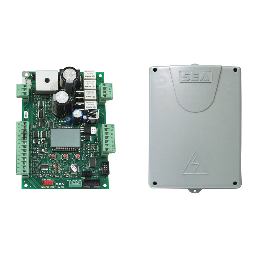
- Page 1 International registered trademark n. 2.777.971 USER 2 - 24V DG “ALL IN” ELECTRONIC CONTROL UNIT 24V FOR SWING GATES 67411656...
-
Page 2: Table Of Contents
USER 2 - 24V DG “ALL IN” International registered trademark n. 2.777.971 INDEX DETAILS ............................3 CONNECTIONS..........................5 DESCRIPTION OF THE COMPONENTS..................6 GENERAL INFORMATION ......................7 QUICK START ..........................8 SELFLEARNING WORKING TIME....................9 SELECTION OF SETTINGS .......................10 RADIO TRANSMITTER SELF LEARNING WITH RECEIVER ON BOARD OF CONTROL UNIT ............................17 DELETE TRANSMITTERS ......................17 FUNCTIONING LOGICS......................18... -
Page 3: Details
USER 2 - 24V DG “ALL IN” International registered trademark n. 2.777.971 Details General An appliance shall be provided with an instruction manual. The instruction manual shall give instructions for the installation, operation, and user maintenance of the appliance. The installation instructions shall specify the need for a grounding-type receptacle for connection to the supply and shall stress the importance of proper grounding. - Page 4 USER 2 - 24V DG “ALL IN” International registered trademark n. 2.777.971 g) The Stop and/or Reset button must be located in the line-of-sight of the gate. Activation of the reset control shall not cause the operator to start. h) A minimum of two (2) WARNING SIGNS shall be installed, one on each side of the gate where easily visible. i) For gate operators utilizing a non-contact sensor: 1) See instructions on the placement of non-contact sensors for each Type of application, 2) Care shall be exercised to reduce the risk of nuisance tripping, such as when a vehicle, trips the sensor while the gate is...
-
Page 5: Connections
USER 2 - 24V DG “ALL IN” International registered trademark n. 2.777.971 CONNECTIONS WARNING: The control unit is designed with the automatic detection of not used N.C. inputs (photocells, Stop and Limit switch) except the SAFETY EDGE input. RADIO MODULE (CNA) 13 12 11 10 9 Receiver module connector JOLLY... -
Page 6: Description Of The Components
USER 2 - 24V DG “ALL IN” International registered trademark n. 2.777.971 DESCRIPTION OF THE COMPONENTS POWER DISPLAY DOWN PROG JOLLY MF1 - MF2 = Mosfet motor 2 CN1 = Input/Output connector MF3 - MF4 = Mosfet motor 1 CN2 = Limit switch, electro-lock connector POWER = 24V~ power supply connection CN3 = Motors connector PROG = Programming connector... -
Page 7: General Information
USER 2 - 24V DG “ALL IN” International registered trademark n. 2.777.971 GENERAL INFORMATION The information in this section of the manual are only for technicians or for qualified or authorized installers. GENERAL CHARACTERISTICS The USER 2 24V DG “ALL IN” control unit has been designed to manage one or two low voltage swing gate operators with or without electronic limit switches. -
Page 8: Quick Start
USER 2 - 24V DG “ALL IN” International registered trademark n. 2.777.971 QUICK START PROGRAMMING BUTTONS MENU MENU LANGUAGE ITALIANO DOWN OK to exit Menu Skip this step if you do not want to program a transmitter or press the button of the next Press the TX to be stored... -
Page 9: Selflearning Working Time
USER 2 - 24V DG “ALL IN” International registered trademark n. 2.777.971 WORKING TIMES SELF LEARNING The control unit is pre-set with the default settings, to start the control unit with the DEFAULT settings just keep pressed the UP and DOWN buttons at the same time power supplying the control unit the display shows the message init. -
Page 10: Selection Of Settings
USER 2 - 24V DG “ALL IN” International registered trademark n. 2.777.971 SELECTION OF THE SETTINGS The settings of the control unit are made through the UP, DOWN and OK buttons. The UP and DOWN buttons to scroll through the MENUS and SUBMENUS. - Page 11 USER 2 - 24V DG “ALL IN” International registered trademark n. 2.777.971 MENU FUNCTIONS TABLE USER 2 24V DG “ALL IN” Description MENU Default Set value tal ano Italian engl sk English 1 - langvage tal ano fran(a s French espanol Spanish dut(k...
- Page 12 USER 2 - 24V DG “ALL IN” International registered trademark n. 2.777.971 PRESS AT THE SAME TIME FOR 5 SECONDS TO ENTER OR TO EXIT THE SPECIAL MENU DOWN SPECIAL MENU FUNCTIONS TABLE USER 2 24V DG “ALL IN” To ENTER the Special Menu keep pressed UP and DOWN at the same time for 5 seconds. To EXIT the Special Menu pressed END or keep pressed UP and DOWN at the same time for 5 seconds.
- Page 13 USER 2 - 24V DG “ALL IN” International registered trademark n. 2.777.971 Description Set Value MENU SP Default Disabled 15 - open ng sloudoun 2 Setting from 5 to 100 Disabled 16 - (los ng sloudoun 2 Setting from 5 to 100 Pre-flashing active only Only (los ng before closing...
- Page 14 USER 2 - 24V DG “ALL IN” International registered trademark n. 2.777.971 Description Set Value MENU SP Default Nor al Normal N.C. contact Nor al 29 - edge Edge is active and protected by a 8k2 resistor Photocell active in (LOS NG closing Photocell active in...
- Page 15 USER 2 - 24V DG “ALL IN” International registered trademark n. 2.777.971 Description Set Value MENU SP Default 24Vaux output always ALUAYS power supplied 24V output active only N (Y(LE during cycle 24Vaux output power OPEN NG supplied only during opening 24Vaux output power (LOS NG 32 - 24u avx...
- Page 16 USER 2 - 24V DG “ALL IN” International registered trademark n. 2.777.971 Description Set Value MENU SP Default Adjust the amperometric 42 -OPEN NG TOLERAN(E tolerance in relation to the 0 100 otor 1 detected stop in opening Adjusts the amperometric 43 - (LOS NG TOLERAN(E tolerance in relation to the 0 100...
-
Page 17: Radio Transmitter Self Learning With Receiver On Board Of Control Unit
USER 2 - 24V DG “ALL IN” International registered trademark n. 2.777.971 RADIO TRANSMITTER SELF LEARNING WITH RECEIVER ON BOARD OF CONTROL UNIT WARNING: Make the radio transmitters programming before you connect the antenna and insert the receiver into the special CMR connector (if available) with turned off control unit. -
Page 18: Functioning Logics
If the password has been forgotten, the only way to unlock the control unit is to contact the SEA technical assistance, which will assess whether to provide the procedure to unlock the control unit or not. -
Page 19: Start, Stop, Pedestrian Start, Antenna, Photocell Connections
USER 2 - 24V DG “ALL IN” International registered trademark n. 2.777.971 START - STOP - PEDESTRIAN START - ANTENNA - PHOTOCELL Photocell 1 and Photocell 2 Connections + = 24VL COM = 0V PH1 = Photocell contact 1 PH2 = Photocell contact 2 Note1: For the autotest connect in the menu 32-24uavk the TX to the 24VAux clamp and activate the Autotest function. -
Page 20: Amperometric Management, Electro-Lock, Warning Lamp, Edge Connections
USER 2 - 24V DG “ALL IN” International registered trademark n. 2.777.971 AMPEROMETRIC MANAGEMENT AMPEROMETRIC DEVICE FOR ELECTROMECHANICAL OPERATORS This control unit comes with an obstacle detection system working only on electromechanical operators allowing to have the reversing on obstacles and the automatic detection of the stops. The sensitivity is adjustable for single leaf and single opening and closing direction through the torque parameter. -
Page 21: Limit Switch, External Receiver Connections
USER 2 - 24V DG “ALL IN” International registered trademark n. 2.777.971 LIMIT SWITCH Limit switch If not connected they don't have to be bridged. For the limit switch function the presence of the limit switches in both closing and opening is necessary. It is possible to activate the function anti-intrusion. -
Page 22: Power Supply And Motors Connections
USER 2 - 24V DG “ALL IN” International registered trademark n. 2.777.971 POWER SUPPLY - MOTORS 115V~ 230V~ 3,6 A delayed fuse on 230V ~ power supply . 6,3A delayed fuse on 115V ~ power supply. FLIPPER ALPHA STD BETA Motor 2 Output for Motor 2 connection... -
Page 23: Connection Of Batteries
USER 2 - 24V DG “ALL IN” International registered trademark n. 2.777.971 CONNECTION OF BATTERIES TO BATTERY CHARGER CARD Cod.23101105 NOTE: On the test menu it is possible to = charge 200mA see batteries charge level. = charge 360mA = charge 800mA GND PSOL BAT 28V (BAT) -
Page 24: Alarms Indications, Alarm Signals
USER 2 - 24V DG “ALL IN” International registered trademark n. 2.777.971 ALARMS INDICATIONS Signals Kind of alarm Solutions FA LVRE OTOR Motors current failure Sure there are no short circuits on the motors or on the control unit. Make sure there are no short circuits on the wiring or on the control unit and 24V Power supply FA LVRE24 no overloads. -
Page 25: Trouble Shooting
Materials handling must be made with appropriate vehicles.. WARRANTY LIMITS For the guarantee see the sales conditions on the official SEA price list. SEA reserves the right to make any required modification or change to the products and/or to this manual without any advanced notice obligation. 67411656... - Page 26 PAYMENT: Method of payments and terms are notified by SEA and displayed on the commercial invoice. DELIVERY: The delivery time on the invoice is not binding and represents an estimated delivery. Shipments costs will be charged to the buyer and SEA is not responsible for delays and/or damages occurred to the products during shipment.
Need help?
Do you have a question about the USER 2 24V DG ALL IN and is the answer not in the manual?
Questions and answers