Table of Contents
Advertisement
Quick Links
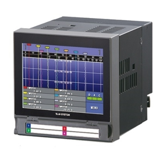
73VR1100 PAPERLESS RECORDER
STARTUP GUIDE
- Read Before Installation -
1.
POINTS OF CAUTION ...................................................................... 2
2.
PACKAGE INCLUDES... .................................................................... 5
3.
ITEMS TO PREPARE........................................................................ 6
4.
COMPONENT IDENTIFICATION ........................................................... 7
5.
EXTERNAL DIMENSIONS .................................................................. 9
6.
INSTALLING THE UNIT .................................................................... 10
7.
PREPARATION & WIRING TO THE UNIT ................................................ 12
8.
SETTING UP THE RECORDER ............................................................ 15
9.
LET'S START RECORDING ............................................................... 23
Contents
- 1 -
EM-7399-A Rev.9
Advertisement
Table of Contents

Subscribe to Our Youtube Channel
Related Manuals for M-system 73VR1100


Summary of Contents for M-system 73VR1100
-
Page 1: Table Of Contents
73VR1100 PAPERLESS RECORDER STARTUP GUIDE – Read Before Installation – Contents POINTS OF CAUTION ..............2 PACKAGE INCLUDES............... 5 ITEMS TO PREPARE................ 6 COMPONENT IDENTIFICATION ............7 EXTERNAL DIMENSIONS ..............9 INSTALLING THE UNIT ..............10 PREPARATION & WIRING TO THE UNIT ..........12 SETTING UP THE RECORDER ............ -
Page 2: Points Of Caution
• Supplying any level of power other than specified above can damage the 73VR1100 or the power source. • The power cables and the signal I/O cables for the 73VR1100 must be located sepa- rately. • The main circuit cables (high voltage and high current), the signal I/O cables, and the power cables should not be bundled together or placed near each other. - Page 3 • Do not use the 73VR1100 in an environment where flammable gases are present. This may result in an explosion. • Do not disassemble or modify the 73VR1100 in any way. Doing so may result in a fire or an electrical shock.
- Page 4 73VR1100 is without external power supply. • The data will be reset to its default status when the battery is used up while the 73VR1100 is left without power supply for a long time period. The clock adjustment will be nec- essary once the power is restored.
-
Page 5: Package Includes
PACKAGE INCLUDES... Please confirm that all items mentioned below are included in the package. Paperless Recorder Startup guide (this booklet) Mounting bracket (two pieces) Software CD (73VRPAC2) Not included for desktop type. – 5 –... -
Page 6: Items To Prepare
• CF card reader The CF card reader is required to read the card contents into a PC. • Refer to Users Manuals stored in the 73VRPAC2 CD for detailed operations of the 73VR1100. Paperless Recorder (model: 73VR1100) Users Manual, Connecting with I/O devices ............ -
Page 7: Component Identification
Insert a CF Card. (4) Eject Button Used to retrieve the CF Card. (5) Reset Button Used to restart the 73VR1100. (6) CF Card Access Indicator LED Red light turns on during the CF Card is accessed. (7) USB Connector Connect an USB flash-memory. - Page 8 (11) Power Indicator LED (12) Power Input Terminal (13) RUN Output Terminal (8) RS-485 Terminal Block Used to connect the 73VR1100 to its I/O devices via RS-485. (9) LAN Port Connects the LAN cable (10BASE-T or 100BASE-TX) (10) RUN Output Indicator LED Green light turns on in normal conditions;...
-
Page 9: External Dimensions
EXTERNAL DIMENSIONS Unit: mm (inch) ■ PANEL MOUNT TYPE 136.5 (5.37) 133 (5.24) 151.5 (5.96) 29.2 2 to 26 panel thickness 144 (5.67) (1.15) (.08 to 1.02) Attach the mounting bracket either on the top/bottom or on the sides. – 9 –... - Page 10 DESKTOP TYPE 136.5 (5.37) 144 (5.67) 133 (5.24) 29.2 (1.15) – 10 –...
-
Page 11: Installing The Unit
INSTALLING THE UNIT Mount the 73VR1100 on the surface of a panel. ■ ADAPTABLE PANEL Panel thickness: 2 to 26 mm Material: Steel ■ PANEL CUTOUT Unit: mm ■ SINGLE MOUNTING ■ VERTICAL CLUSTERED MOUNTING (max. 3 units) Number (mm) - Page 12 ■ PANEL MOUNTING (1) Insert the 73VR1100 from the front side of the panel. (2) Remote the sheets covering the mounting bracket holes. Fix two mounting brackets either on the sides or on the top and bottom of the unit. Tighten screws.
-
Page 13: Preparation & Wiring To The Unit
(5) Close the front cover. NOTES – Hot to Take the CF Card Out – (1) When the 73VR1100 is recording data, touch [ MENU ] key on the right bottom on the screen and touch [ Stop ] to stop the recording. - Page 14 SETTING UP & CONNECTING I/O DEVICES ■ SETTING UP THE R1M-GH2 Node address and signal type must be set. (1) Node address Set the rear rotary switch to ‘1.’ If the power is supplied to the R1M-GH2 when setting the address, turn off and on the power supply to enable the new setting.
- Page 15 *1. Internal terminating resistors are used for the devices at both end of a transmission line. Close across the terminals DB and TR for the 73VR1100, T2 and T3 for the R1M-GH2. *2. Install shielded cables to all sections and ground them at a single point.
-
Page 16: Setting Up The Recorder
(model: R1M-GH2) ☛ See the 73VR1100 User’s Manual (EM-7399-C, Section 6) for the setting details. (1) Insert the CF card into the 73VR1100. Turn on the power supply to the 73VR1100. NOTES – Creating Files in the CF Card –... - Page 17 (3) Touch [ Config. ]. (4) Touch [Quick setup ] in Main setup view. (5) ‘Basic setting’ view is on the screen. Touch [ Next ]. NOTES – Control Key Functions – Cancel : Return to Main setup view without ap- plying changes made in Quick setup.
- Page 18 (7) ‘Node setting’ view is on the screen. Touch [ Node 1 ] field to show available options. Choose ‘R1M-GH2’ and touch [ Next ]. (8) ‘Enable/disable pens’ view is on the screen. Touch [ Next ]. (9) Available selections for ‘Enable/disable pens’ are on the screen.
- Page 19 (11) ‘ A nalog/Discrete pens’ view is on the screen. Touch [ Next ]. (12) Available selections for ‘ A nalog/Discrete pens’ are on the screen. Choose ‘ A nalog’ for Pen 1. Touch [ Next ]. (13) ‘Tag’ view is on the screen. Touch [ Next ].
- Page 20 (15) ‘Engineering unit’ view is on the screen. Touch [ Next ]. (16) Default engineering units are on the screen. Touch these units to change. Touch the current unit selection for Pen 1 and a keypanel appears on the screen. The following is an example to set ‘V’...
- Page 21 (17) ‘Channel’ view is on the screen. Touch [ Next ]. (18) Default channel numbers are on the screen. Touch these channel numbers to change. Touch the current unit selection for Pen 1 and a keypanel appears on the screen. Enter ‘1’...
- Page 22 (21) ‘Input range’ view is on the screen. Touch [ Next ]. (22) Default input ranges are on the screen. Touch these range value fields to change. Touch the current selections for Pen 1 and a keypanel appears on the screen. Enter ‘-5.0’...
- Page 23 (25) Now the basic setting is complete. Touch [ Record ]. NOTES Scaling range is automatically set as the plot position for the pen when you use Quick setup. – 23 –...
-
Page 24: Let's Start Recording
LET’S START RECORDING CONFIRMING THE 73VR1100 OPERATION WITH SIMULATED INPUT Confirm that the 73VR1100 is functioning properly using a simulated input signal. Connect a voltage simulator to Channel 1 terminals (+ to 1, – to 2) and supply 5V DC. - Page 25 • ‘Trend View,’ ‘Overview,’ ‘Bargraph View’ and ‘Graphic View’ plotting recorded data in real time. • ‘Retrieve View’ and ‘ A larm History’ showing data stored in the CF card. ☛ See 73VR1100 Users Manual (EM-7399-C, Section 8) for detail. Trend View Overiew...
Need help?
Do you have a question about the 73VR1100 and is the answer not in the manual?
Questions and answers