Table of Contents
Advertisement
Quick Links
Advertisement
Table of Contents

Subscribe to Our Youtube Channel
Related Manuals for M-system TR30 Series


Summary of Contents for M-system TR30 Series
- Page 1 Paperless Recorder TR30 Series PAPERLESS RECORDER Model: TR30-G USERS MANUAL 5-2-55, Minamitsumori, Nishinari-ku, Osaka 557-0063 JAPAN Tel: +81-6-6659-8201 Fax: +81-6-6659-8510 http://www.m-system.co.jp/ E-mail: info@m-system.co.jp TR30-G USERS MANUAL EM-8631-G Rev.16...
-
Page 2: Table Of Contents
Ta ble of Con tents 1. Introduction 1.1 User manual compatible versions ......................8 1.2 Precautions ............................9 1.3 Component identification ......................... 10 2. Installation 2.1 Preparations ............................ 12 2.2 Installation and wiring ........................12 2.3 Preparation of configurator software ....................13 2.3.1 Configurator software for the TR30: TRGCFG .................. - Page 3 3.8.3 Analog input (AI) ............................36 Assignment of the I/O module to AI ....................36 Assignment of remote I/O to AI .......................38 Assignment of SLMP device to AI....................40 Assignment of control input to AI ....................42 Assignment of time input to AI ......................42 Basic setting (AI)..........................44 Alarm zone setting (AI) ........................46 Upward setting / Downward setting (AI) ..................48...
- Page 4 3.9 Web server setting ......................... 108 3.9.1 Name setting ............................108 3.9.2 Trend screen display setting ........................109 Pen setting ............................ 109 Page name setting .........................111 3.9.3 Login ID / password / port address setting ..................... 112 3.9.4 Trend graph orientation setting (vertical/horizontal) ................114 3.10 Recording method setting ......................
- Page 5 4.3.2 Operation ............................... 147 Switch pages ..........................147 Switch scale (%, scaling value) ....................147 Change the maximum/minimum value of the scale ..............148 Switch between show / hide pen ....................149 Expand / compress the time axis ....................150 Compare graphs (Shifting the scale orientation)................
- Page 6 4.11.2 Operation .............................. 179 Write comment ..........................179 Open event summary ........................180 Open comment summary ......................180 4.12 Change setting ..........................181 4.12.1 Alarm threshold ............................ 182 4.12.2 E-mail setting ............................184 Address list setting ........................184 Report setting ..........................185 4.12.3 Pen configuration ..........................
- Page 7 7. Appendix 7.1 Primary method of operation of the touch panel ................207 7.2 Troubleshooting ..........................208 7.2.1 Lamp display ............................208 7.2.2 SD card ..............................208 7.2.3 Web server .............................208 7.2.4 TRGCFG ..............................209 7.2.5 LAN connection ............................210 7.2.6 Wi-Fi connection ............................. 210 7.2.7 Internet ..............................
-
Page 8: Introduction
1. Introduction Thank you for choosing M-System. Before use, please check the following information. 1.1 User manual compatible versions The versions compatible with this User Manual are as follows. ■ UNIT VERSION This User Manual is compatible with model TR30-G Unit version 2.2 or later. -
Page 9: Precautions
• With power on, the battery is not drained. When total power off period is approx. 2 years, the battery cannot backup the calendar clock. The calendar clock cannot keep correct date and time. • The battery is not replaceable by customer. When replacement is required, consult M-System. ■ AND .. -
Page 10: Component Identification
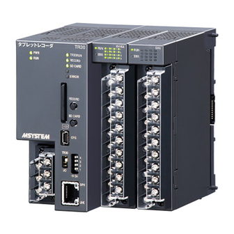
1.3 Component identification FRONT VIEW SIDE VIEW Positioning Guide Status Indicator LEDs TR30 RUN Logging Button SD Card Slot RECORD SD CARD SD Button ERROR Configuration Connector Configuration Select SW RECORD SD CARD Function Setting DIP SW Terminal Fixing Screw Terminal Block for TR30... - Page 11 ■ ETHERNET INDICATOR LED COLOR FUNCTION Green ON during full duplex transmission Amber ON while link is established. ■ CONFIGURATOR SELECT SW SW POSITION CONFIGURATION OBJECT TR30 Configuring the TR30 (*) Configuring the R30 series I/O modules (*) Factory setting ■...
-
Page 12: Installation
• User Manual for each of the above *1 *1. The software programs are available for downloading at M-System web site. ➔ http://www.m-system.co.jp/ In addition, depending on the system configuration, a Wi-Fi router or a fixed IP address contract is necessary. -
Page 13: Preparation Of Configurator Software
2.3.1 Configurator software for the TR30: TRGCFG Installation Download TRGCFG from the website of M-System, and complete the installation simply by extracting it into any folder. Use the shortcut to TRGCFG.exe which has been extracted to the desktop as required. - Page 14 NOTES • If the driver software is not automatically installed, and the added COM port is not listed in the options, please download the driver from M-System website http://www.m-system.co.jp and install it. • The added COM port No. varies from PC to PC.
-
Page 15: Configurator Software For The I/O Module: R30Cfg
2.3.2 Configurator software for the I/O module: R30CFG Installation Please install by referring to the R30CFG User Manual. R30CFG startup (1) Set the [Configuration Select Switch] of the device as [I/O]. TR30 RUN RECORD SD CARD Configuration ERROR Connector Configuration Select SW RECORD TR30... -
Page 16: Explanation About The Basic Working And Terms
2.4 Explanation about the basic working and terms Term Explanation 4 types of input channels and 1 type of output channel are defined in a device. The I/O signals are in the form of fully encoded digital data. : Analog input (16 bit signed integer, unsigned integer) Channel : Digital input (1 bit) : Pulse input (32 bit unsigned integer, signed integer, floating point) -
Page 17: Setting
3. Setting 3.1 Setting flow Before starting to record using a device, follow the procedure given below to configure the setting. Setting during initial startup ▼ Network setting ▼ System setting ▼ I/O module connection setting ▼ Remote I/O connection setting ▼... -
Page 18: Setting During Initial Startup
3.2 Setting during initial startup In order to prevent exhaustion of the battery being used for calendar IC backup in this device, the calendar clock backup is disabled in the factory shipment setting. Hence, in its initial state, it will not work using the cor- rect time. - Page 19 (5) Click on the [Date/Time] button. The current time of the PC which is in use is initially displayed. Enter the time to be set and click on the [Apply] button. The time which you have set is applied in the calendar IC of the device. Initial Screen Con rm access mode 1.
-
Page 20: Network Setting
3.3 Network setting The TR30 is equipped with Web server functions. With the help of these functions, a PC, tablet terminal or smartphone can be used for remote monitoring. And, setting changes can either be made via a network, or the FTP server function can be used to transfer or delete data which is stored in the device from a PC. -
Page 21: Connect Using A Local Area Network (Lan)
3.3.1 Connect using a local area network (LAN) Depending on the server functions of the TR30 which are used, please set according to the table below. Please consult the network administrator for details about the setting. Server function which is used Network setting for the TR30 Web server FTP server... -
Page 22: Set The Ip Address
3.3.3 Set the IP address Use TRGCFG to configure the network setting. (1) Set the [Configuration Select Switch] of the device as [TR30]. TR30 RUN RECORD SD CARD Configuration ERROR Connector Configuration Select SW RECORD TR30 SD CARD TR30 V (-) (2) Connect the PC and the device using a USB cable. -
Page 23: Enable Setup Via A Network
3.3.4 Enable setup via a network Setup can be done using TRGCFG via a network. Please set up TRGCFG by following the procedure given below. (1) Set the [Configuration Select Switch] of the device as [TR30]. TR30 RUN RECORD SD CARD Configuration ERROR Connector... - Page 24 (6) Click on the [Upload to device] button to transfer the setting to the device, and then restart to the TR30 to activate the setting. In TRGCFG, press the [Back] button and return to the [Initial Screen]. Initial Screen Con rm access mode 1.
- Page 25 (8) Double-click on the line containing the connection destination to be registered and display the registration dialog. Set the name and connection destination (Domain name or IP address), and click on the [OK] but- ton. Up to 32 connection destinations can be registered. Initial Screen Connect 1.
-
Page 26: System Setting
3.4 System setting You can set a system name and description of your choice and display it on the Web screen. (1) Set the [Configuration Select Switch] of the device as [TR30]. TR30 RUN RECORD SD CARD Configuration ERROR Connector Configuration Select SW RECORD... -
Page 27: Name
Refer to the following and configure the required setting such as the name. Name Set the Name (1, 2, 3) using less than 32 characters. Language Select the language to be used on the Web screen as Japanese or English. Time zone Set the time zone in Hours: (-12 to 13) and Minutes: (0 to 59) JST is [+09: 00]. -
Page 28: Built-In I/O Module Setting
3.5 Built-in I/O module setting Next, please set each of built-in modules. Please use R30CFG for setting. (1) Set the [Configuration Select Switch] of the device as [I/O]. TR30 RUN RECORD SD CARD Configuration ERROR Connector Configuration Select SW RECORD TR30 SD CARD TR30... -
Page 29: Remote I/O Connection Setting
3.6 Remote I/O connection setting Using the Modbus/TCP master function of the TR30, I/O can be expanded using remote I/O nodes with a Mod- bus/TCP slave function. Switching HUB TR30 Slave 0 Slave 1 Slave 2 Slave 3 A maximum of 12 remote I/O nodes can be connected to 1 device. Please set different IP addresses which do not overlap with the address of the TR30 for the remote I/O (Slave 0 to Slave 11). -
Page 30: Slmp Device Connection Setting
3.7 SLMP device connection setting Using the SLMP client function of the TR30, I/O can be expanded using SLMP devices. Switching HUB MELSEC iQ-R MELSEC iQ-F MELSEC Q Series Series Series CPU Module CPU Module CPU Module TR30 Slave 0 Slave 1 Slave 2 At the maximum of 12 SLMP devices can be connected to single TR30 device. -
Page 31: I/O Setting
3.8 I/O setting Next, please configure the I/O setting. Use TRGCFG to configure the setting. (1) Set the [Configuration Select Switch] of the device as [TR30]. TR30 RUN RECORD SD CARD Configuration ERROR Connector Configuration Select SW RECORD TR30 SD CARD TR30 V (-) (2) Connect the PC in which TRGCFG is installed with the device, and start up TRGCFG. - Page 32 NOTES The parameters for which the engineering unit value is set in TRGCFG can be set between ±10,000,000,000. The maximum number of digits that can be entered after the decimal point equals the number of digits which is displayed on the screen. For example, since the scale 0% for the analog input has an initial value of 0.000, when [123.4567890] is entered, it is rounded off to 3 digits after the decimal point to match the initial value 0.000, and therefore becomes [123.457].
-
Page 33: I/O Slave Setting
3.8.1 I/O slave setting Modbus/TCP remote I/O and SLMP devices that are used to communicate with the TR30 must be identified with each IP address and relevant settings. The Pause period and Timeout setting are common to all slave devices. Assignment of remote I/O (1) In the [Input/Output] screen, click on the [I/O slave setting] button. -
Page 34: Assignment Of Slmp Device
Assignment of SLMP device (1) In the [Input/Output] screen, click on the [I/O slave setting] button. Input/Output I/O slave setting Slave setting 1. Click 2. Double-click (2) Double-click on the row containing the slave to be set to open the slave setting. (3) Choose [SLMP ...]. -
Page 35: Communication Setting
3.8.2 Communication Setting (1) In the [Input/Output] screen, click on the [I/O slave setting] button. (2) Click on the [Communication] to display the Communication setting. Input/Output I/O slave setting Communication setting 1. Click 2. Click 3. Enter • Pause period Considering the communication pertaining to all the registered slaves and all the channels as one batch, set the time from one communication batch to the next. -
Page 36: Analog Input (Ai)
3.8.3 Analog input (AI) Analog input signals can be monitored for a maximum of 64 points (AI1 to AI64). Please assign the analog input from the connected I/O module or remote I/O to the TR30 by following the procedure given below. Assignment of the I/O module to AI (1) Click on the [Analog input (AI)] button on the [Input/Output] screen to display the [Analog input (AI)] screen. - Page 37 (3) Set the [CH setting] as [I/O module] to enable the [Module address] and [CH No.]. Please enter the CH value to be assigned. 2. Enter 1. Select In case of analog input, up to 4 ch can be assigned per module. Module category Compatible module CH No.
-
Page 38: Assignment Of Remote I/O To Ai
Assignment of remote I/O to AI (1) Go first through the I/O slave setting for the remote I/O device. ➔ 3.8.1 I/O slave setting (2) Display the [AI setting] just as in case of the I/O module. Input/Output Analog input (AI) AI setting 1. - Page 39 (3) Set the [CH setting] as [Modbus/TCP], and enter the [Modbus/TCP slave No.], [Modbus/TCP register type] and [Modbus/TCP register address]. 1. Select 2. Enter Parameter Description Modbus/TCP slave No. Enter the slave No. (0 to 11) set in (1). Modbus/TCP register type Select from [Input Register (3X)] or [Holding Register (4X)].
-
Page 40: Assignment Of Slmp Device To Ai
Assignment of SLMP device to AI (1) Go first through the I/O slave setting for the SLMP device. ➔ 3.8.1 I/O slave setting (2) Display the [AI setting] just as in case of the I/O module. Input/Output Analog input (AI) AI setting 1. - Page 41 (3) Set the [CH setting] as [SLMP], and enter the parameters in the table below. 2. Enter 1. Select 3. Enter Parameter Description Slave No. Enter the slave No. (0 to 11) set in (1). SLMP device Choose the device code of the SLMP device to be connected. SLMP device No.
-
Page 42: Assignment Of Control Input To Ai
Assignment of control input to AI Input values can be specified from remote locations by writing values in the internal registers using the Mod- bus/TCP slave function. NOTES Please see [3.11.4 Modbus/TCP slave] and [7.3.7 Modbus/TCP slave] for information on the Modbus/TCP slave function and internal registers. - Page 43 (2) Set the [CH setting] as [Time], and select the item to be used as the input value from [hour / minutes / seconds]. 1. Select 2. Select TR30-G USERS MANUAL EM-8631-G Rev.16...
-
Page 44: Basic Setting (Ai)
Basic setting (AI) Once the assignment is complete, configure the following basic setting. Click on the [OK] button to temporarily store the setting. AI setting Enter Parameter Description CH name Set a name for the channel which is less than 16 characters. Set a description for the channel which is less than 16 characters using the tag name, CH comment etc. - Page 45 The CH name and CH comment which have been set are displayed in the initial screen or the trend of the Web screen. CH name CH comment TR30-G USERS MANUAL EM-8631-G Rev.16...
-
Page 46: Alarm Zone Setting (Ai)
Alarm zone setting (AI) Configure alarm zone setting corresponding to the input values. A maximum of 5 zones can be set, and dead- band can also be set between zones. (1) Click on the [Alarm zone setting] button in the [AI setting] to display the [Alarm zone setting]. AI setting AI alarm zone setting Click... - Page 47 (2) Set various parameters by referring to the table below. Parameter Description Partitions Set the number of partitions to be used. You can select from: Not to be used / 2 / 3 / 4 / 5. Name Set a name which is less than 32 characters for each zone. Color Set a color to represent each zone which will be displayed on the Web screen.
-
Page 48: Upward Setting / Downward Setting (Ai)
Upward setting / Downward setting (AI) This event occurs when the zone which has been set in the zone setting is changed. (1) Click on the [Alarm zone setting] button in the [AI setting] to display the [Alarm zone setting]. Click on the tab [Upward] or [Downward]. - Page 49 Message Acknowledge Event No. Message TR30-G USERS MANUAL EM-8631-G Rev.16...
-
Page 50: Alarm Output (Ai)
Alarm output (AI) A specific DO can be turned ON for each zone. The DO channel to be operated needs to be first assigned in [Discrete output (DO)]. (1) Click on the [Alarm zone setting] button in the [AI setting] to display the [Alarm zone setting]. Click on the [Alarm output] button of a specific zone to display the [Alarm output]. - Page 51 (2) Double-click on the DO channel to be operated and set as ON/OFF. Alarm output 1. Double-click 2. Select (3) Once the setup is complete, press the [OK] button and temporarily store the setting. CAUTION • Before configuring these setting, configure the DO setting. ➔...
-
Page 52: Reset Totalized Value (Ai)
Reset totalized value (AI) The cumulative total value of a specific PI can be reset during zone transition. (1) Click on the [Alarm zone setting] button in the [AI setting] to display the [Alarm zone setting]. Click on the [Reset totalized value] button in a specific zone to display the [Reset totalized value]. AI setting AI alarm zone setting 1. - Page 53 (2) Double-click on the PI channel to be operated and set as Disable / Enable. Reset totalized value 1. Double-click 2. Select (3) Once the setup is complete, press the [OK] button and temporarily store the setting. TR30-G USERS MANUAL EM-8631-G Rev.16...
-
Page 54: Reset Function Value (Ai)
Reset function value (AI) The operation of a specific OI can be reset during zone transition. (1) Click on the [Alarm zone setting] button in the [AI setting] to display the [Alarm zone setting]. Click on the [Reset function value] button in a specific zone to display the [Reset function value]. AI setting AI alarm zone setting 1. - Page 55 (2) Double-click on the OI channel to be operated and set as Disable / Enable. Reset function value 1. Double-click 2. Select (3) Once the setup is complete, press the [OK] button and temporarily store the setting. Use the above procedure to set all the CHs. The CH setting for which the setting is complete in the [Analog input (AI)] screen can also be copied to other CHs and only the required portions can be edited.
-
Page 56: Discrete Input (Di)
3.8.4 Discrete input (DI) Digital input signals can be monitored for a maximum of 64 points (DI1 to DI64). Please assign the digital input from the connected I/O module or remote I/O to the device by following the procedure given below. Assignment of the I/O module to DI (1) Click on the [Discrete input (DI)] button in the [Input/Output] screen to display the [Discrete input (DI)] screen. - Page 57 (2) Set the [CH setting] as [I/O module] to enable the [Module address] and [CH No.]. Please enter the CH value to be assigned. 1. Select 2. Enter In case of discrete input, up to 16 ch can be assigned per module. Card type Compatible card CH No.
-
Page 58: Assignment Of Remote I/O To Di
Assignment of remote I/O to DI (1) Go first through the I/O slave setting for the remote I/O device. ➔ 3.8.1 I/O slave setting (2) Display the [AI setting] just as in case of the I/O module. Input/Output Discrete input (DI) 1. - Page 59 (3) Set the [CH setting] as [Modbus/TCP], and enter the [Modbus/TCP slave No.], [Modbus/TCP register type] and [Modbus/TCP register address]. 1. Select 2. Enter Parameter Description Modbus/TCP slave No. Enter the slave No. (0 to 11) set in (1). Modbus/TCP register type Select from [Input (1X)] or [Coil (0X)].
-
Page 60: Assignment Of Slmp Device To Di
Assignment of SLMP device to DI (1) Go first through the I/O slave setting for the SLMP device. ➔ 3.8.1 I/O slave setting (2) Display the [DI setting] just as in case of the I/O module. Input/Output Discrete input (DI) 1. - Page 61 (3) Set the [CH setting] as [SLMP], and enter the parameters in the table below. 1. Select 2. Enter 3. Enter Parameter Description Slave No. Enter the slave No. (0 to 11) set in (1). SLMP device Choose the device code of the SLMP device to be connected. SLMP device No.
-
Page 62: Assignment Of Analog Input (Ai) For Di
Assignment of analog input (AI) for DI A specific bit among 16 bits of AI word data can be assigned to a DI. (1) Display the [DI setting] just as in case of the I/O module. Input/Output Discrete input (DI) 1. -
Page 63: Assignment Of Control Input To Di
Assignment of control input to DI Input values can be specified from remote locations by writing values in the internal registers using the Mod- bus/TCP slave function. NOTES Please see [3.11.4 Modbus/TCP slave] and [7.3.7 Modbus/TCP slave] for information on the Modbus/TCP slave function and internal registers. -
Page 64: Basic Setting (Di)
Basic setting (DI) Once the assignment is complete, configure the following basic setting. Click on the [OK] button to temporarily store the setting. DI setting Enter Enter TR30-G USERS MANUAL EM-8631-G Rev.16... - Page 65 Parameter Description CH name Set a channel name which is less than 16 characters. CH comment Set a description for the channel which is less than 16 characters using the tag name, etc. If the ON/OFF in the input signal and the ON/OFF in the application signal are the reverse of each Invert logic other, put a check in the check box.
- Page 66 Message Acknowledge Event No. Message CAUTION If the new memory block lasts for a short time, data on a memory block which has not been transferred to the SD card may get overwritten. Set the new memory block interval as a multi- ple of 10 seconds.
-
Page 67: Alarm Output (Di)
Alarm output (DI) A specific DO can be turned ON for each status. (1) Click on the [Alarm output] button in the [DI setting] to display the [Alarm output]. Double-click on the DO channel to be operated and set as ON/OFF. DI setting Alarm output 3. -
Page 68: Pulse Input (Pi)
3.8.5 Pulse input (PI) Pulse input signal can be monitored for a maximum of 32 points (PI1 to PI32). 32 bit integer data such as energy data can also be assigned to PI. Please assign the pulse input from a remote I/O which has been connected to the device by following the pro- cedure given below. - Page 69 (3) Set the [CH setting] as [I/O module] to enable the [Module address] and [CH No.]. Please enter the CH value to be assigned. 1. Select 2. Enter In case of pulse input, up to 2 ch can be assigned per module. Module category Compatible module CH No.
-
Page 70: Assignment Of Remote I/O To Pi
Assignment of remote I/O to PI (1) Go first through the I/O slave setting for the remote I/O device. ➔ 3.8.1 I/O slave setting (2) Display the [PI setting] just as in case of the I/O module. Input/Output Pulse input (PI) PI setting 1. - Page 71 Modbus/TCP register address If you do not want to reverse the higher and lower registers, remove the check from the [Invert] check box. To use the remote I/O which is a product of M-System, put the check. (4) Set the parameters in the following table.
-
Page 72: Assignment Of Slmp Device To Pi
Assignment of SLMP device to PI (1) Go first through the I/O slave setting for the SLMP device. ➔ 3.8.1 I/O slave setting (2) Display the [PI setting] just as in case of the I/O module. Input/Output Pulse input (PI) PI setting 1. - Page 73 (3) Set the [CH setting] as [SLMP], and enter the parameters in the table below. 1. Select 2. Enter 3. Enter Parameter Description Slave No. Enter the slave No. (0 to 11) set in (1). SLMP device Choose the device code of the SLMP device to be connected. Set the device No.
-
Page 74: Assignment Of Control Input To Pi
Assignment of control input to PI Input values can be specified from remote locations by writing values in the internal registers using the Mod- bus/TCP slave function. NOTES Please see [3.11.4 Modbus/TCP slave and 7.3.7 Modbus/TCP slave for information on the Modbus/TCP slave function and internal registers. - Page 75 (2) Set the [CH setting] as [Analog accumulation], and enter the [AI CH No.], [Counter rate], [Time unit] and [Low-end cutout]. 1. Select 2. Enter Analog Accumulation Analog input is treated as pulse input. 12000 Unit Time 10000 AI% data The rectangular area equals “Counter Rate.”...
-
Page 76: Assignment Of The Discrete Input (Di) To Pi
Assignment of the Discrete Input (DI) to PI The cumulative total can be obtained by considering the DI input values as the number of pulses. (1) Display [PI setting Dialogue] as same case of Remote I/O device. Input/Output Pulse input (PI) PI setting 1. - Page 77 (2) Set the [ CH setting] [DI], and set each parameter as shown below. 1. Select 2. Enter 3. Enter Item Description DI CH Number Select the CH Number of DI assigned. Select the measuring mode from ON/OFF/UP/DOWN, determining of input values based on sample signal of every on second.
-
Page 78: Basic Setting (Pi)
Basic setting (PI) Once the assignment is complete, please configure the following basic setting. Click on the [OK] button to temporarily store the setting. PI setting Parameter Description CH name Set a channel name which is less than 16 characters. Set a description for the channel which is less than 16 characters using the tag name, CH comment etc. -
Page 79: Alarm Zone Setting (Pi)
Alarm zone setting (PI) Configure alarm zone setting corresponding to the input values. A maximum of 5 zones can be set, and dead- bands can also be set between zones. (1) Click on the [Alarm zone setting] button in the [PI setting] to display the [PI Alarm zone setting]. PI setting PI alarm zone setting Click... -
Page 80: Upward Setting / Downward Setting (Pi)
Upward setting / Downward setting (PI) This event occurs when the zone which has been set in the alarm zone setting is changed. (1) Click on the [Alarm zone setting] button in the [PI setting] to display the [PI Alarm zone setting]. Click on the tab [Upward] or [Downward]. - Page 81 Message Acknowledge Event No. Message CAUTION If the new memory block lasts for a short time, data on a memory block which has not been transferred to the SD card may get overwritten. Set the new memory block interval as a multi- ple of 10 seconds.
-
Page 82: Alarm Output (Pi)
Alarm output (PI) A specific DO can be turned ON for each zone. (1) Click on the [Alarm zone setting] button in the [PI setting] to display the [PI Alarm zone setting]. Click on the [Alarm output] button in a specific zone to display the [Alarm output]. PI setting PI alarm zone setting 1. - Page 83 (2) Double-click on the DO channel to be operated and set as ON/OFF. Alarm output 1. Double-click 2. Select (3) Once the setup is complete, press the [OK] button and temporarily store the setting. CAUTION • Configure the DO setting before configuring these setting. ➔...
-
Page 84: Reset Totalized Value (Pi)
Reset totalized value (PI) During zone transition, the cumulative total value of a specific PI can be reset. (1) Click on the [Alarm zone setting] button in the [PI setting] to display the [PI Alarm zone setting]. Click on the [Reset totalized value] button in a specific zone to display the [Reset totalized value]. PI setting PI alarm zone setting 1. - Page 85 (2) Double-click on the PI channel to be operated and set as Disable/Enable. Reset totalized value 1. Double-click 2. Select (3) Once the setup is complete, press the [OK] button and temporarily store the setting. TR30-G USERS MANUAL EM-8631-G Rev.16...
-
Page 86: Reset Function Value (Pi)
Reset function value (PI) During zone transition, the operation of a specific OI can be reset. (1) Click on the [Alarm zone setting] button in the [PI setting] to display the [PI Alarm zone setting]. Click on the [Reset function value] button in a specific zone to display the [Reset function value]. PI setting PI alarm zone setting 1. - Page 87 (2) Double-click on the OI channel to be operated and set as Disable / Enable. Reset function value 1. Double-click 2. Select (3) Once the setup is complete, press the [OK] button and temporarily store the setting. Set each CH by following the above procedure. The CH setting for which the setting is complete in the [Pulse input (PI)] screen can also be copied to other CHs and only the required portions can be edited.
-
Page 88: Function Input (Oi)
3.8.6 Function input (OI) Function input can be done for a maximum of 32 points (OI1 to OI32). Please use the following procedure to configure the setting for the device. Basic setting (OI) Configure the following basic setting. Click on the [OK] button to temporarily store the setting. OI setting Parameter Description... - Page 89 ■ Operation specifications Operation name Formula Parameters K1, K2, K3, A0: Constant Addition and K1X1 + K2X2 + K3X3 + A0 X1, X2, X3: AI1 - 64, DI1 - 64, PI1 - 32, OI1 - 32 subtraction Use engineering unit values. DI: ON=1.0, OFF=0.0 K1, K2, A0, A1, A2: Constant Multiplication (K1X1 + A1)(K2X2 + A2) + A0...
- Page 90 ■ Action when there is an error Operation name Process When K2X2 + A2 = 0, consider the previous value as the operation value. Division Record the contents in the system log. When X1 is negative, consider the previous value as the operation value. Square root Record the contents in the system log.
-
Page 91: Alarm Zone Setting (Oi)
Alarm zone setting (OI) Configure alarm zone setting corresponding to the input values. A maximum of 5 zones can be set, and dead- bands can also be set between zones. (1) Click on the [Alarm zone setting] button in the [OI setting] to display the [OI Alarm zone setting]. OI setting OI alarm zone setting 1. -
Page 92: Upward Setting / Downward Setting (Oi)
Upward setting / Downward setting (OI) This event occurs when the zone which has been set in the alarm zone setting is changed. (1) Click on the [Alarm zone setting] button in the [OI setting] to display the [OI Alarm zone setting]. Click on the tab [Upward] or [Downward]. - Page 93 Message Acknowledge Event No. Message TR30-G USERS MANUAL EM-8631-G Rev.16...
-
Page 94: Alarm Output (Oi)
Alarm output (OI) A specific DO can be turned ON for each zone. (1) Click on the [Alarm zone setting] button in the [OI setting] to display the [OI Alarm zone setting]. Click on the [Alarm output] button in a specific zone to display the [Alarm output]. OI setting OI alarm zone setting 1. - Page 95 (2) Double-click on the DO channel to be operated and set as ON/OFF. Alarm output 1. Double-click 2. Select (3) Once the setup is complete, press the [OK] button and temporarily store the setting. CAUTION • Configure the DO setting before configuring these setting. ➔...
-
Page 96: Reset Totalized Value (Oi)
Reset totalized value (OI) During zone transition, the cumulative total value of a specific PI can be reset. (1) Click on the [Alarm zone setting] button in the [OI setting] to display the [OI Alarm zone setting]. Click on the [Reset totalized value] button in a specific zone to display the [Reset totalized value]. OI setting OI alarm zone setting 1. - Page 97 (2) Double-click on the PI channel to be operated and set as Disable/Enable. Reset totalized value 1. Double-click 2. Select (3) Once the setup is complete, press the [OK] button and temporarily store the setting. TR30-G USERS MANUAL EM-8631-G Rev.16...
-
Page 98: Reset Function Value (Oi)
Reset function value (OI) During zone transition, the operation of a specific OI can be reset. (1) Click on the [Alarm zone setting] button in the [OI setting] to display the [OI Alarm zone setting]. Click on the [Reset function value] button in a specific zone to display the [Reset totalized value]. OI setting OI alarm zone setting 1. - Page 99 (2) Double-click on the OI channel to be operated and set as Disable / Enable. Reset function value 1. Double-click 2. Select (3) Once the setup is complete, press the [OK] button and temporarily store the setting. Please set each CH by following the above procedure. The CH setting for which the setting is complete in the [Pulse input (PI)] screen can also be copied to other CHs and only the required portions can be edited.
-
Page 100: Discrete Output (Do)
3.8.7 Discrete output (DO) Discrete output (DO1 to DO64) can be output from a maximum of 64 points. Please assign the discrete output from the connected I/O module or remote I/O to the device by following the procedure given below. Assignment of the I/O module to DO (1) Click on the [Discrete output (DO)] button in the [Input/Output] screen to display the [Discrete output (DO)] screen. - Page 101 In case of discrete output, up to 16 ch can be assigned per module. Module type Compatible module CH No. Slot address CH No. in the module R30YN16A 16 ch module R30YN16C CH10 CH11 CH12 CH13 CH14 CH15 CH16 N: Slot address TR30-G USERS MANUAL EM-8631-G Rev.16...
-
Page 102: Assignment Of Remote I/O To Do
Assignment of remote I/O to DO (1) Go first through the I/O slave setting for the remote I/O device. ➔ 3.8.1 I/O slave setting (2) Display the [DO setting] just as in case of the I/O module. Input/Output Discrete output (DO) DO setting 1. -
Page 103: Assignment Of Slmp Device To Do
Assignment of SLMP device to DO (1) Go first through the I/O slave setting for the SLMP device. ➔ 3.8.1 I/O slave setting (2) Display the [DO setting] just as in case of the I/O module. Input/Output Discrete output (DO) DO setting 1. -
Page 104: Basic Setting (Do)
Basic setting (DO) Once the assignment is complete, please configure the following basic setting. Click on the [OK] button to temporarily store the setting. DO setting Enter Parameter Description CH name Set a channel name which is less than 16 characters. CH comment Set a description for the channel which is less than 16 characters using the tag name, etc. -
Page 105: Which Functions Assigned To Do
Which functions assigned to DO? The list of functions in which alarm output has been set is displayed. Input/Output Discrete output (DO) Which functions assigned to DO? 1. Click 2. Click TR30-G USERS MANUAL EM-8631-G Rev.16... -
Page 106: Copying The Ch Setting
3.8.8 Copying the CH setting The CH setting for which the setting is complete in the CH list screen (Example: Analog input (AI) screen) can also be copied to other CHs and only the required portions can be edited. 1. Right-click on the row to be copied Click on [Copy] 2. -
Page 107: Applying The Setting
3.8.9 Applying the setting To transfer the temporarily stored setting values to the device, please click on the [Back] button from the [Input/ Output] screen to return to the [Configuration], and then click on the [Upload to device] button. Input/Output Con guration Con rm uploading 1. -
Page 108: Web Server Setting
3.9 Web server setting You can set the page names, pen colors, etc. displayed on the Web server screens. 3.9.1 Name setting Set Name 1, 2 and 3 by referring to [3.4 System setting]. Name 1 Name 2 Name 3 TR30-G USERS MANUAL EM-8631-G Rev.16... -
Page 109: Trend Screen Display Setting
3.9.2 Trend screen display setting Pen setting You set the pen assignment, color and other setting for the trend displayed on the Web screen. You can display a maximum of 120 pens on a total of 30 pages with Pen 1 - Pen 4 on Page 1, Pen 5 - Pen 8 Page 2, etc. - Page 110 (6) Double-click on the row containing the pen number which you want to set. The [Pen setting] is displayed. 1. Double-click Pen setting 2. Enter Please configure the pen setting by referring to the table below. Click on the [OK] button to temporarily store the setting.
-
Page 111: Page Name Setting
Page name setting You can set the name of each page displayed in the trend screen. (1) Click on the [Page name] button in the [Pen] screen to display the [Page name] screen. Set a name which is less than 64 characters for each page. 1. -
Page 112: Login Id / Password / Port Address Setting
3.9.3 Login ID / password / port address setting Web browsing can be password locked. Please set as follows. You can also change the HTTP port address. (1) Start up TRGCFG. (2) Click on the [Download from device] button. (3) If the [Confirm access mode] is displayed, check that the device is correct, and click on the [Connect] but- ton. - Page 113 (5) Click on the [Communication] button. (6) The [Communication] screen is displayed. Click on the [Web server] button. The [Web server] screen is displayed. Con guration 1. Click Communication 2. Click Web server 3. Enter Please set various parameters by referring to the table below. Parameter Description Default value...
-
Page 114: Trend Graph Orientation Setting (Vertical/Horizontal)
3.9.4 Trend graph orientation setting (vertical/horizontal) Please see [4.1 Initial screen (Group selection screen)]. TR30-G USERS MANUAL EM-8631-G Rev.16... -
Page 115: Recording Method Setting
3.10 Recording method setting Recording data is first written into memory blocks in the internal memory of the unit. Once a specified time or number of samples is reached, the recording moves to the next memory block. During this transition, the recording data in the previous memory block is transferred to the SD card (if the SD card has been inserted). -
Page 116: Storing Rate
(6) Click on the [Record] button. The [Record] screen is displayed. Con guration Record 1. Click Please set the following parameters. Storing rate Set the storing rate. You can select from: 5 ms / 10 ms / 50 ms / 100 ms / 500 ms / 1 seconds / 2 seconds / 5 seconds / 10 seconds / 1 minute / 2 minutes / 5 minutes / 10 minutes / 15 minutes / 30 minutes /1 hour. -
Page 117: Start New Memory Block
Start new memory block Set the timing at which a new memory block is created. Please set various parameters by referring to the table below. Parameter Description Default value Usable transition intervals depend upon the selected storing rate. Interval With [Max] setting, a new memory block is created when the number of trend data points reaches 50000. -
Page 118: Communication Function Setting
3.11 Communication function setting 3.11.1 FTP server Using the FTP server function built into the TR30, you can perform remote transfer/deletion of files in the SD card inserted into the device. (1) Set the [Configuration Select Switch] of the device as [TR30]. TR30 RUN RECORD SD CARD... - Page 119 (6) Click on the [Communication] button. (7) The [Communication] screen is displayed. Click on the [FTP server] button. The [FTP server] screen is displayed. Con guration 1. Click Communication 2. Click 3. Select [Enable] FTP server 4. Enter Please set the items by referring to the table below. Parameter Description Default value...
-
Page 120: Ftp Client
3.11.2 FTP client You can use the FTP client function built into the TR30 to send the files stored in the SD card to the FTP server. (1) Set the [Configuration Select Switch] of the device as [TR30]. TR30 RUN RECORD SD CARD Configuration... - Page 121 (6) Click on the [Communication] button. (7) The [Communication] screen is displayed. Click on the [FTP client] button. The [FTP client] screen is displayed. Con guration 1. Click Communication 2. Click 3. Select [Enable] FTP client 4. Enter Please set the parameters by referring to the table below. Parameter Description Default value...
-
Page 122: Sntp
3.11.3 SNTP You can automatically correct the time using the SNTP client function built into the TR30. Automatic time correction is done at power on and 00:00, 06:00, 12:00 and 18:00 hours. (1) Set the [Configuration Select Switch] of the device as [TR30]. TR30 RUN RECORD SD CARD... - Page 123 (6) Click on the [Communication] button. (7) The [Communication] screen is displayed. Click on the [SNTP] button. The [SNTP] screen is displayed. Con guration 1. Click Communication 2. Click 3. Select [Enable] SNTP 4. Enter Please set the parameters by referring to the table below. Parameter Description Default value...
-
Page 124: Modbus/Tcp Slave
3.11.4 Modbus/TCP slave By using the Modbus/TCP slave function built into the TR30, you can perform various operations including online monitoring from outside. • By setting the internal registers as [Enable], operations such as [Start/stop recording], [Start new memory block] and [Comment insertion] can be performed from external devices such as PLCs. •... - Page 125 (6) Click on the [Communication] button. (7) The [Communication] screen is displayed. Click on the [Modbus/TCP slave] button. [Modbus/TCP slave] screen is displayed. Con guration 1. Click Communication 2. Click 3. Select [Enable] Modbus/TCP slave 4. Enter Please set the parameters by referring to the table below. Parameter Description Default value...
-
Page 126: Mail Reporting
3.11.5 Mail reporting Mail reporting can be done using the function built into the TR30. There are 2 kinds of mail reports: [Event report] which is sent during zone transition, and [Regular report] which are sent at preset times. The TR30 does not have a function to receive mail. SMPT / POP3 setting (1) Set the [Configuration Select Switch] of the device as [TR30]. - Page 127 (6) Click on the [Communication] button. (7) The [Communication] screen is displayed. Click on the [SMTP/POP3] button. The [SMTP/POP3] screen is displayed. Con guration 1. Click 2. Click 3. Select [Enable] Communication SMTP/POP3 4. Enter TR30-G USERS MANUAL EM-8631-G Rev.16...
- Page 128 Please set the parameters by referring to the table below. Parameter Description Default value Set the character code for the mail. Character code UTF-8 UTF-8 ISO-2022-JP SMTP over SSL Configure encrypted Connect setting. To use, set as [Enable]. Disable Configure SMTP authentication setting. Disable: Do not carry out SMTP authentication.
- Page 129 Setting examples for popular free e-mail services are shown in the following table (As of Nov. 2015). Parameter Yahoo mail (Yahoo Japan) Gmail (Google) SMTP over SSL Disable Enable SMTP authentication Automatic Automatic Before @ in the mail address Mail address Example: dl8 Example: dl8@gmail.com Registered password...
-
Page 130: Mail Setting
Mail setting (1) Set the [Configuration Select Switch] of the device as [TR30]. TR30 RUN RECORD SD CARD Configuration ERROR Connector Configuration Select SW RECORD TR30 SD CARD TR30 V (-) (2) Connect the PC in which TRGCFG is installed with the device, and start up TRGCFG. (3) Click on the [Download from device] button. - Page 131 (6) Click on the [E-mail] button. (7) The [E-mail] screen is displayed. Click on the [Address list] button. The [Address list] screen is displayed. Double-click on the Address list row to be registered, and register the Name and Address (mail address). You can register up to 32 addresses as the Address list.
- Page 132 (8) Click on the [Event report] button to display the [Event report] screen. Register the mail document for the event report here. Double-click on the row with the mail number to be registered as the event report. The registration screen is displayed.
- Page 133 (9) Click on the [Address list] button. The [Address list] screen is displayed. Double-click on the row containing the registered Address list, and select from: None / To / Cc. Mail registration 1. Click Address list 2. Double-click 3. Select TR30-G USERS MANUAL EM-8631-G Rev.16...
- Page 134 (10) Configure the setting related to the most recent input value report to be appended at the end of the mail document. Click on the [Attach CH data] (AI - DO) button. The [CH information (AI - DO)] screen is displayed. To dis- play it as the input value report, double-click on the row containing the relevant CH, and set it as [Enable].
- Page 135 (11) When the mail reporting is successful, configure the setting for the DO to be operated. Click on the [DO] button. The [DO] screen is displayed. Double-click on the row containing the CH to be operated, and select from: [None], [ON] and [OFF]. Mail registration 1.
- Page 136 (13) For regular reporting, please click on the [Regular report] button. The [Regular report] screen is displayed. Please configure the setting for [Mode], [Address list], [Subject], [Body text], [Attached CH data] and [DO operation] just as for the [Event report]. Con guration 1.
- Page 137 (14) For a [Regular report], you can specify the day (of the week) when it should be sent. Regular report 1. Click Specify day of week 2. Select (15) Please set the time to send the [Regular report] between 0 and 23 hours. To report, set the [Report] as [Enable].
- Page 138 (16) You can configure the report failure output setting to detect a mail reporting failure. Click on the [Delivery failure output] button. The [Delivery failure output] screen is displayed. Select from: [None] or [DO1 - 64]. Con guration 1. Click 2.
-
Page 139: Other Settings
3.12 Other settings 3.12.1 TRGCFG setting You can configure the setting so that the [Confirm access mode] is not displayed when connecting to the TR30. (1) Start up TRGCFG. (2) Remove the check against [Confirm access mode when connecting.] in the initial screen. (3) The [Confirm access mode] will no longer be displayed. -
Page 140: Ftp Status Monitoring
3.12.2 FTP status monitoring The status of data uploading by FTP can be confirmed during the setup procedure using one of the following methods. Checking by TRGCFG (1) Connect the TR30 to a PC with an USB cable. (2) Turn ON the function setting DIP SW1. TR30 RUN RECORD SD CARD... -
Page 141: Checking By A Terminal Software Program
Checking by a terminal software program (1) Connect the TR30 to a PC with an USB cable. (2) Turn ON the function setting DIP SW1. TR30 RUN RECORD SD CARD ERROR RECORD SD CARD Function Setting DIP SW TR30 V (-) (3) Start up the terminal software program and set as follows: Transmission speed: 38400 bps Data bit: 8... -
Page 142: How To Use The Web Server
4. How to use the Web server Please enter the domain name or IP address in the URL entry field of the browser. The [Group selection] screen is displayed. We shall now describe the method of operation method based on a tablet terminal (iPad). 4.1 Initial screen (Group selection screen) The trend screen consists of P1 - P30. -
Page 143: Menu Bar
4.2 Menu bar A common menu bar is displayed in screens other than the [Group selection] screen. 4.2.1 Display contents Error indicator Memory block indicator Screen lock indicator Current date Current time SD card indicator Start recording button Menu button Unacknowledged event indicator Menu button Tap the Menu button... -
Page 144: Error Indicator
Error indicator If a module which has been set is not actually inserted, the mark is displayed. ➔ 7.2 Troubleshooting Start recording button When recording into the device is in progress, the green color is ON ( ), and while recording is stopped, it is OFF ( Tap to start/stop recording. -
Page 145: Trend
4.3 Trend Tap the [Menu button ] and select [Trend ] to switch to the [Trend] screen. 4.3.1 Display contents The [Trend] screen consists of a [Menu bar], [Page selector] and [Trend area]. Menu bar Page selector Page name Trend area Digital display Scale Pen pointer... -
Page 146: Digital Display
Digital display If the color of the characters is black, it means that the current value is being displayed. When you scroll the trend graph, the top values of the graph are displayed, and the color of the characters becomes blue. Tap the [Digital display] to make the pen selected. -
Page 147: Operation
4.3.2 Operation Switch pages Tap the [Page selector] to switch pages. A maximum of 4 pens are assigned to 1 page. Even when the [Menu] is displayed, you can tap the button and switch pages. Switch scale (%, scaling value) You can switch the scale display between % and scaling value. -
Page 148: Change The Maximum/Minimum Value Of The Scale
Change the maximum/minimum value of the scale You can change the maximum value and minimum value of the scale. (1) Lock the screen. (2) Tap the [Digital display] for the pen that you want to change, and select the pen. (3) If you want to change the maximum value, tap the blank area to the right of the scale, and to change the minimum value, tap the blank area to the left of the scale. -
Page 149: Switch Between Show / Hide Pen
Switch between show / hide pen You can hide the trend graph for the selected pen. (1) Tap the [Pen color] in the [Digital display] of the pen that you want to hide. (2) The color of the characters for that pen number turns dark, and the trend graph for that pen is hidden. The [Pen pointer] is displayed as usual. -
Page 150: Expand / Compress The Time Axis
Expand / compress the time axis You can hide the trend graph for the selected pen. (1) Tap the [Menu button ] and display the [Menu]. (2) Tap [Compress time axis ], or [Expand time axis ] in the sub-menu. Each tap of the button causes the time axis on the trend graph to compress/expand. -
Page 151: Compare Graphs (Shifting The Scale Orientation)
Compare graphs (Shifting the scale orientation) You can shift the trend graph for a selected pen. (1) Tap [Screen lock indicator] and lock the screen. (2) Tap [Digital display] for the pen that you want to move, and make the pen selected. (3) Swipe the trend graph area in the desired direction. -
Page 152: Compare Graphs (Scale Expansion / Contraction)
Compare graphs (Scale expansion / contraction) You can expand/contract the trend graph of the selected pen. (1) Tap the [Screen lock indicator] and lock the screen. (2) Tap the [Digital display] for the pen that you want to move and make the pen selected. (3) If you Pinch in/Pinch out in the trend graph area, the graph expands/contracts. -
Page 153: Comment Entry
Comment entry You can write comments in a trend graph. Comments are displayed across all pages. The list of comments which have been entered can be checked in the [Comment summary] screen. (1) Tap the [Menu button (2) Tap [Write comment ] in the sub-menu. -
Page 154: New Event
4.4 New event Tap the [Menu button ] and select [New event ] to go to the [New event] screen. 4.4.1 Display contents The list of new events is displayed. During I/O setting in TRGCFG, if there are events for which there is a check against [Register new event] in the status setting for the zone in each channel, the information on such events is displayed in this screen. -
Page 155: Operation
4.4.2 Operation Filter the display by event number (New event) You can filter the display by event number. (1) Tap the [Event No.] button. (2) The [Event No.] is displayed. Tap the number that you want to display. Only the event for the selected event number is displayed. -
Page 156: Confirm An Unacknowledged Event (New Event)
Confirm an unacknowledged event (New event) An event which has been set as [Acknowledge: required] in the event log setting is displayed in orange color as an [Unacknowledged event]. It can be changed into a confirmed event by tapping. (1) Tap [ACK] for the event that you want to confirm. (2) The dialog [Acknowledge event?] is displayed. -
Page 157: Display Historical Trend
Display historical trend (1) Tap the event for which you want to display the trend and make it selected. (2) Tap the [Menu button ] and tap the [Go to Trend (Event)] button. (3) The historical trend screen containing the selected event is displayed. 1. -
Page 158: Delete From New Events
Delete from new events (1) Tap the new event that you want to delete and make it selected. (2) Tap the [Menu button ] and tap the [Delete event] button. (3) The event is deleted from the new event list. 1. -
Page 159: Overview
4.5 Overview Tap the [Menu button ] and select [Overview ] to switch to the [Overview] screen. 4.5.1 Display contents The alarm generation status of all channels is displayed. Specifically, in the background of the display area for each channel, the color of the area and status corre- sponding to its current value are displayed. -
Page 160: Operation
4.5.2 Operation Display the enlarged screen Tap the [CH selection button] to display the enlarged screen. If the AI data type has been set as [%], you can switch between the [Actual value] and [%] by tapping the measurement value. Tap to close ■... - Page 161 ■ Enlarged screen of DI, DO CH name CH comment Status comment Status color ■ Enlarged screen of PI, OI CH name CH comment Measurement value Engineering unit Zone color Zone name TR30-G USERS MANUAL EM-8631-G Rev.16...
-
Page 162: Event Summary
4.6 Event summary Tap the [Menu button ] and select [Event summary ] to switch to the [Event summary] screen. 4.6.1 Display contents The list of event logs is displayed. Unacknowledged event indicator Number lter Unacknowledged event Swipe to scroll Unacknowledged event (Event summary) If there is even one unacknowledged event in any of the memory blocks in internal memory, the mark is... -
Page 163: Operation
4.6.2 Operation Filter the display by event number (Event summary) You can filter the display by event number. (1) Tap the [Event No.] button. (2) The [Event No.] is displayed. Tap the number that you want to display. Only the event for the selected event number is displayed. -
Page 164: Confirm An Unacknowledged Event (Event Summary)
Confirm an unacknowledged event (Event summary) In the event log setting, events which have been set as [Acknowledge: required] are displayed in orange as [Unacknowledged events]. Tap to confirm the event. (1) Tap [ACK] for the event that you want to confirm. (2) The dialog [Acknowledge event?] is displayed. -
Page 165: Comment Summary
4.7 Comment summary Tap the [Menu button ] and select [Comment summary ] to go to the [Comment summary] screen. 4.7.1 Display contents The list of comments is displayed. The color of the characters during comment entry is also displayed as it is. Menu bar Block being selected Date... -
Page 166: Delete Comment
Delete comment You can delete any comment. (1) Tap on the comment that you want to delete to select it. The row containing the selected comment turns blue in color. (2) Tap the [Menu button (3) Tap [Delete comment ] in the sub-menu. (4) The confirmation dialog [Do you want to delete the selected comment?] is displayed. -
Page 167: Group Selection
4.8 Group selection Tap the [Menu button ] and select [Select group ] to return to the [Initial screen (group selection screen)]. For details, please see [4.1 Initial screen (Group selection screen)]. TR30-G USERS MANUAL EM-8631-G Rev.16... -
Page 168: Internal Memory
4.9 Internal memory Tap the [Menu button ] and select [Internal memory ] to go to the [Internal memory] screen. 4.9.1 Display contents The list of memory blocks in internal memory is displayed. Menu bar Memory block Block being selected SD card transfer complete icon Swipe to scroll... -
Page 169: Operation
4.9.2 Operation Call up data You can display the trend graph of the selected memory block. (1) Tap the memory block that you want to display to select it. The row containing the selected memory block turns blue in color. (2) Tap the [Menu button (3) Tap [Open historical trend ] in the sub-menu. -
Page 170: Delete Data
Delete data You can delete data in a memory block. (1) Tap the memory block that you want to delete to select it. The row containing the selected memory block turns blue in color. (2) Tap the [Menu button (3) Tap [Delete data ] in the sub-menu. -
Page 171: Transfer Data To The Sd Card
Transfer data to the SD card You can forcibly transfer memory block data to the SD card. (1) Tap the memory block whose data you want to transfer to the SD card. The row containing the selected memory block turns blue in color. (2) Tap the [Menu button (3) Tap [Transfer to SD ] in the sub-menu. -
Page 172: New Memory Block
New memory block You can forcibly perform transition of a memory block which is to be recorded. (1) Tap the [Menu button (2) Tap [New memory block ] in the sub-menu. (3) The confirmation dialog [Record in the next memory block?] is displayed. Tap the [OK] button. (4) After the transition, the [OK] is displayed. -
Page 173: Sd Card
4.10 SD card Tap the [Menu button ] and select [SD card ] to go to the [SD card] screen. 4.10.1 Display contents The list of data stored in the SD card is displayed. Menu bar Current folder Folder contents List of folders List of les [Reference] If the above folders are displayed in Windows 7 Explorer, they will appear as shown below. -
Page 174: Operation
4.10.2 Operation Select SD card file The data stored in the SD card is stored in a specified folder during each storing rate. ➔ 7.3.4 SD card Please change the folder to be displayed as described below, and select the desired data file. •... -
Page 175: Call Up Data
Call up data You can display a trend graph for the selected data file. (1) Select the data file that you want to display. The row containing the selected data file turns blue in color. (2) Tap the [Menu button (3) Tap [Display data ] in the sub-menu. -
Page 176: Delete Data
Delete data You can delete a selected data file. (1) Tap the data file that you want to delete to select it. The row containing the selected data file turns blue in color. (2) Tap the [Menu button (3) Tap [Delete data ] in the sub-menu. -
Page 177: Historical Trend
4.11 Historical trend You can display the trend for data stored in the SD card in internal memory (in TRD format). We now describe the method of operation of this screen. 4.11.1 Display contents The [Historical trend] screen broadly consists of a [Menu bar], [Page selector] and [Trend area]. Menu bar Page selector Page name... -
Page 178: Digital Display
Digital display The value at the top of the graph is displayed. Tap [Digital display] to make the pen selected. The background turns black. To unselect the pen, tap the scale display. Pen color CH name CH comment Digital display Pen selected % display NOTES... -
Page 179: Operation
4.11.2 Operation The method of operation is basically the same as the [Trend] screen. Please see [4.3 Trend]. Here, we describe the operations which are different from the [Trend] screen. Write comment You can add comments in the trend graph. Comments are displayed across all pages. The list of comments which have been entered can be checked in the [Comment summary] screen. -
Page 180: Open Event Summary
Open event summary You can display the summary of events containing the displayed data. (1) Tap the [Menu button (2) Tap the [Go to event summary ] in the sub-menu. (3) The [Event summary] screen is displayed. Please see [4.6 Event summary] for the method of operation. Open comment summary You can display the summary of comments containing the displayed data. -
Page 181: Change Setting
4.12 Change setting Tap the [Menu button ] and tap [Setting ] to display the [Setting] menu. NOTES To display screens other than [Reset local calibration], network connection permission is required for TRGCFG. ➔ 3.3.4 Enable setup via a network TR30-G USERS MANUAL EM-8631-G Rev.16... -
Page 182: Alarm Threshold
4.12.1 Alarm threshold You can change the alarm threshold for analog input, pulse input and function input. (1) Tap the [Alarm threshold] button from the [Setting]. (2) The [Alarm selection] screen for analog input is displayed. To change the alarm threshold for pulse input, tap the [PI] button, and to change the alarm threshold for function input, tap the [OI] button. - Page 183 (5) Once all the zones have been changed, tap the [OK] button on the top right. (6) The [confirmation] is displayed. Please tap the [OK] button. (7) After the setting are reflected, the [OK] is displayed. Please tap the [OK] button. 1.
-
Page 184: E-Mail Setting
4.12.2 E-mail setting You can change the Address list and the report content setting. Address list setting (1) Tap the [E-mail setting] button from the [Setting]. (2) The [E-mail setting] screen is displayed. Tap the [Address list] button. (3) Enter the [Name] and [E-mail address]. (4) Once all the changes are complete, tap the [OK] button. -
Page 185: Report Setting
Report setting (1) Tap the [E-mail setting] button from the [Setting]. (2) The [E-mail setting] screen is displayed. Tap the [Report setting] button. (3) Tap the [Edit] which is on the right of the report for which you want to make changes. (4) Set the [Subject, Body text, Mode and Address list]. - Page 186 (7) To generate a test mail, tap the [Test mail]. 1. Tap CAUTION When the [Mode] is disabled, the relevant event report setting is also changed accordingly. For temporarily disabling a particular mail registration, choose [None] in [Address list]. TR30-G USERS MANUAL EM-8631-G Rev.16...
-
Page 187: Pen Configuration
4.12.3 Pen configuration You can change the pen assignment. (1) Tap the [Pen configuration] button from the [Setting]. (2) Tap the pen that you want to change to make it selected. The background turns blue in color. Tap once again to display the [Edit pen configuration] screen. (3) Change the assignment, color and the lower limit/upper limit values, and tap the [OK] button. -
Page 188: Reset Local Calibration
4.12.4 Reset local calibration You can reset the setting values such as the maximum and minimum values for each pen in the trend graph. (1) Tap the [Reset local calibration] button from the [Setting]. (2) The confirmation dialog [OK to reset local calibration?] is displayed. Tap the [OK] button. (3) The local adjustment value is reset, and the trend graph position returns to the reset value. -
Page 189: Maintenance
4.13 Maintenance Tap the [Menu button ] and select [Maintenance ] to display the [Maintenance]. For details, please see [6.2 Maintenance from the Web screen]. TR30-G USERS MANUAL EM-8631-G Rev.16... -
Page 190: User Defined Screens
4.14 User defined screens Using HTML or JavaScript, you can freely create Web screens. Create a working folder on the PC, and copy the HTML or similar content file. Specify this folder in TRGCFG and send. You can retrieve the current values of data measured using the device as JavaScript data files. Please see [7.3.13 Data files for user defined screen creation]. -
Page 191: Unit Operation
5. Unit operation 5.1 SD card SD card insertion With the terminal surface of the SD card on your left, slowly push the SD card completely into the slot and then remove your hand. If it is correctly recognized, the [SD CARD] lamp comes ON. SD CARD LED ON TR30 RUN RECORD... -
Page 192: Recording
5.2 Recording Start recording Check that the SD card has been recognized. Keep the [RECORD] button pressed for at least 1 second to start recording. SD CARD LED ON TR30 RUN RECORD, SD CARD LED ON RECORD SD CARD SD CARD ERROR RECORD RECORD SD CARD SD CARD TR30 ①... -
Page 193: Stopping The Unit
5.3 Stopping the unit Stop recording, remove the SD card and then disconnect the power supply. TR30-G USERS MANUAL EM-8631-G Rev.16... -
Page 194: Maintenance
6. Maintenance 6.1 Maintenance using TRGCFG 6.1.1 Storage and retrieval of setting values Storage of the setting file TRGCFG can be used to store the setting information in a file. Click on the [Save file] button in the [Configuration] and specify the file path. Con guration 1. -
Page 195: Retrieval Of The Setting File
Retrieval of the setting file The setting information stored in the file can be retrieved using TRGCFG. (1) Click on the [Read file] button in the TRGCFG [Initial screen]. (2) Select the file and click on the [Open] button to retrieve the setting file. Initial Screen 1. -
Page 196: Maintenance
6.1.2 Maintenance Maintenance of the TR30 can be carried out from the [Maintenance] screen. (1) Set the [Configuration Select Switch] of the device as [TR30]. TR30 RUN RECORD SD CARD Configuration ERROR Connector Configuration Select SW RECORD TR30 SD CARD TR30 V (-) (2) Connect the PC in which TRGCFG is installed with the device, and start up TRGCFG. -
Page 197: Time Correction
Time correction Set the calendar clock in the TR30. Click on the [Date/Time] button in the [Maintenance] screen to display the [Date/Time] screen. The current time in the PC which is being used is initially displayed. Enter the time to be set and click on the [Apply] button to reflect the set time in the internal RTC (Real Time Clock) of the device. -
Page 198: Unit Version
Unit version Click on the [TR30-G version] button in the [Maintenance] screen to display the firmware version for the unit. After checking the contents, use the [Back] button to end. Maintenance 1. Click NOTES Please check the version of the I/O modules by using the R30CFG. System log Click on the [System log] button in the [Maintenance] screen to display the system log. -
Page 199: Preset Count
Preset count Click on the [Preset count] button in the [Maintenance] screen to set the preset value for the PI cumulative total data. Select the channel that you want to change, enter the preset value, and then click on the [Upload to device] button. -
Page 200: Initialization
Initialization Memory blocks can be initialized using the [Initialize] button in the [Maintenance] screen. Click on the [Initialize] button to display the [Initialize]. Click on the [Initialize memory block] button. The [confirmation] is displayed. Click on the [OK] button to initial- ize the memory block in the unit. -
Page 201: Ftp Client Test
FTP client test You can send a test FTP request using the [FTP client test] button in the [Maintenance] screen. Click on the [FTP client test] button to display the confirmation dialog. Click on the [OK] button to send the test file. If it cannot be sent, the ERROR lamp blinks. -
Page 202: User Defined Browser View
User defined browser view The screen can be freely built by creating html, js, css etc. files. Click on the [User defined browser view] button to display the [Select folder] screen. Select the working folder and click on the [Convert & Upload to device] button to transfer the data to the unit. Access [http://<TR30-IP address>/user/<content file name>] from the browser. -
Page 203: Maintenance From The Web Screen
6.2 Maintenance from the Web screen Some parameters can be changed even from the Web screen. NOTES To display screens other than the [Display status] screen, network connection authorization is required for TRGCFG. ➔ 3.3.4 Enable setup via a network 6.2.1 Storage and retrieval of setting values Retrieval of the setting file The setting file which is stored in the root folder of the SD card can be retrieved. -
Page 204: Storage Of The Setting File
Storage of the setting file (1) Tap the [Menu button ] to display the menu dialog. (2) Tap [Maintenance ] from the display switching buttons. The [Maintenance] is displayed. Tap the [Save Setting File] button. (3) The [Save Config File] screen is displayed. (4) Tap the input box and enter the file name using single byte alphanumeric characters. -
Page 205: Maintenance
6.2.2 Maintenance Time correction (1) Tap the [Menu button ] to display the menu dialog. (2) Tap [Maintenance ] from the display switching buttons. The [Maintenance] is displayed. Tap the [Time Setting] button. (3) The [Time Setting] screen is displayed. The current time on the terminal being used is initially displayed. (4) Set the date and time and tap the [OK] button. -
Page 206: System Log/Remote I/O Status Display
System log/remote I/O status display (1) Tap the [Menu button ] to display the menu dialog. (2) Tap [Maintenance ] from the display switching buttons. The [Maintenance] is display. Tap the [Status] button. (3) The [Status] screen is displayed. The [Remote I/O status lamp] and [System log] are displayed. Menu bar Remote I/O status lamp... -
Page 207: Appendix
7. Appendix 7.1 Primary method of operation of the touch panel The primary method of operation of the touch panel used in this User Manual is explained below. ■ Tap Lightly tap any point on the screen with your finger and immediately remove your finger. (a light rap) Use to select an item such as an icon or menu. -
Page 208: Troubleshooting
7.2 Troubleshooting 7.2.1 Lamp display Problem faced Checks to be done Method of handling The PWR LED does not Is the tablet recorder powered ON? Check the power supply. come on. The RUN LED does not Perform the same checks as in ---- come on. -
Page 209: Trgcfg
7.2.4 TRGCFG Problem faced Checks to be done Method of handling Unable to connect to the Is the COM port correct? Check the COM port. It should be the same as TR30. the COM number in the [USB Serial Port]. (When using a USB cable to ➔... -
Page 210: Lan Connection
7.2.5 LAN connection Problem faced Checks to be done Method of handling Unable to display the Web Is the IP address correct? Connect using a USB cable, and check the IP server screen via the LAN. address. ➔ 3.3.3 Set the IP address Has the LAN cable come out of the Connect the LAN cable securely. -
Page 211: Internet
7.2.7 Internet Problem faced Checks to be done Method of handling Unable to connect to the Does the information used to Check the setting of the router related to the Internet (provider). connect to the provider match the provider. (Please see the provider information setting in the router (User name, and the User Manual of the router) password, etc.)? -
Page 212: Run Contact
7.2.9 RUN contact Problem faced Checks to be done Method of handling Run contact is off. Has an R30 I/O module been If “module” has been specified in the CH set- installed? ting for the TRGCFG [Input/Output] - [Analog input(AI)], [Discrete input (DI)], [Pulse input (PI)] and[Discrete output (DO)], check if an I/O mod- ule has been installed in the specified slot. -
Page 213: Ftp Server
7.2.11 FTP server Problem faced Checks to be done Method of handling Unable to make an FTP Have the setting of the FTP server Set the mode in the FTP server setting in connection to the TR30 via function for the TR30 been ena- TRGCFG as [Enable]. -
Page 214: Reference Documents
7.3 Reference documents 7.3.1 Compatible terminals and browsers The following environments are verified operation. Terminal Compatible browser iPad, iPhone (iOS 10.2.1) Safari Android tablet (Android 6) Chrome 56.0.2924.87 Windows (7, 8.1, 10) Edge, Internet Explorer 11, Firefox 52.0, Chrome 57.0.2987.98 Browser Mouse operation Touch operation... -
Page 215: Storing Rate And Sampling Cycle
7.3.3 Storing rate and sampling cycle The event detection interval is the same as the sampling cycle. During new memory block, data is automati- cally transferred to the SD card. Storing rate Sampling cycle 5 ms 5 ms 10 ms 5 ms 50 ms 5 ms... -
Page 216: Sd Card
7.3.4 SD card Item Description Type SDHC FAT32 Format Do not use a format other than the one provided by the SD Association for the SD card. Create a file name using the YYMMDDHHMMSS of the first sample. Last character S: Standard time (When Daylight saving time is not used) D: Daylight saving time File name... - Page 217 ■ SD card replacement guidelines The approximate time for the SD card to become full is shown in the table below. Since these are only approx- imate values, they do not guarantee the time for which data can be recorded in the SD card. Further, the life of the SD card has not been considered.
- Page 218 If it is stored in a 4 GB SD card in the CSV format: Storing rate Transfer interval 16 pens 32 pens 64 pens 120 pens 5 ms 3 minutes (36,000 points) 34 hours 10 ms 5 minutes (30,000 points) 69 hours 50 ms 10 minutes (12,000 points)
-
Page 219: Memory Block
7.3.5 Memory block ■ Basic specifications Item Description Total space 4 GB (Uses around 2.5 GB) Number of blocks ■ Trend data Item Description Space 32 MB (50000 samples per block) Storing rate (Primary storing cycle/ 5, 10, 50, 100, 500 ms, 1, 2, 5, 10 seconds, 1, 2, 5, 10, 15, 30 minutes, 1 hour RTC synchronous) Record 4 bytes/sample with each pen Data format... -
Page 220: Ftp Server
7.3.6 FTP server Item Description Windows 7, 8.1, 10 Browser (Internet Explorer 11, Firefox 52.0, FTP client Application Chrome 57.0.2987.98) (Verified operation environment) Explorer FFFTP (1.98g) Maximum number of connections For FTP connection: can be changed (initial value : 21) Port address For passive: 45967 Function... -
Page 221: Modbus/Tcp Slave
7.3.7 Modbus/TCP slave Register map Register Channel Register Channel 10001 10033 DI33 10002 10034 DI34 10003 10035 DI35 10004 10036 DI36 10005 10037 DI37 10006 10038 DI38 10007 10039 DI39 10008 10040 DI40 10009 10041 DI41 10010 DI10 10042 DI42 10011 DI11 10043... - Page 222 Register Channel Register Channel 30001 30033 AI33 30002 30034 AI34 30003 30035 AI35 30004 30036 AI36 30005 30037 AI37 30006 30038 AI38 30007 30039 AI39 30008 30040 AI40 30009 30041 AI41 30010 AI10 30042 AI42 30011 AI11 30043 AI43 30012 AI12 30044 AI44...
- Page 223 Register Channel Register Channel 30201 PI1 (low) 30233 PI17 (low) 30202 PI1 (high) 30234 PI17 (high) 30203 PI2 (low) 30235 PI18 (low) 30204 PI2 (high) 30236 PI18 (high) 30205 PI3 (low) 30237 PI19 (low) 30206 PI3 (high) 30238 PI19 (high) 30207 PI4 (low) 30239...
- Page 224 Register Channel Register Channel 30401 OI1 (low) 30433 OI17 (low) 30402 OI1 (high) 30434 OI17 (high) 30403 OI2 (low) 30435 OI18 (low) 30404 OI2 (high) 30436 OI18 (high) 30405 OI3 (low) 30437 OI19 (low) 30406 OI3 (high) 30438 OI19 (high) 30407 OI4 (low) 30439...
-
Page 225: Internal Registers
Internal registers ■ Operation (recording and transition) Register Item Type Description 0 : Stop 08001 Recording 1 : Record 08002 Transition 1 : Run (Automatically returns to 0 after executed) ■ Status Register Item Type Description 0 : Standing by 18001 SD card recording 1 : Recording in progress... - Page 226 ■ SD card operation (Sub-folder creation and deletion) Register Item Type Description Set the string using ASCII code. 48301 Sub-folder name 1 (Only alphanumeric characters and _ allowed) (1st level) Lower 8 bits are valid. 48332 Set 0 at the end of the string. Set the string using ASCII code.
- Page 227 Control input (AI) Register Channel Register Channel 44001 44033 AI33 44002 44034 AI34 44003 44035 AI35 44004 44036 AI36 44005 44037 AI37 44006 44038 AI38 44007 44039 AI39 44008 44040 AI40 44009 44041 AI41 44010 AI10 44042 AI42 44011 AI11 44043 AI43 44012...
- Page 228 Control input (DI) Register Channel Register Channel 04001 04033 DI33 04002 04034 DI34 04003 04035 DI35 04004 04036 DI36 04005 04037 DI37 04006 04038 DI38 04007 04039 DI39 04008 04040 DI40 04009 04041 DI41 04010 DI10 04042 DI42 04011 DI11 04043 DI43 04012...
- Page 229 Control input (PI) Register Channel Register Channel 44201 PI1 (low) 44233 PI17 (low) 44202 PI1 (high) 44234 PI17 (high) 44203 PI2 (low) 44235 PI18 (low) 44204 PI2 (high) 44236 PI18 (high) 44205 PI3 (low) 44237 PI19 (low) 44206 PI3 (high) 44238 PI19 (high) 44207...
-
Page 230: Commands
Commands ■ Data and control functions CODE NAME Read Coil Status Digital output from the slave Read Input Status Status of digital Inputs to the slave Read Holding Registers General purpose register within the slave Read Input Registers Collected data from the field by the slave Force Single Coil Digital output from the slave Preset Single Register... -
Page 231: Data Range
Data range When the TR30-G device is used as a Modbus/TCP slave, the range of data returned from the slave to the Modbus master and data written by the master is as shown in the table below. Item Description • When the data type is [%] (0 to 10000; voltage/current data of R30 I/O modules or remote I/O devices): -2000 to 12000 •... -
Page 232: Slmp Client
7.3.8 SLMP Client Request Message Request Request Request Request Request destination destination destination destination destination Monitoring Request Header Subheader station multidrop multidrop Footer station unit I/O timer data network station station number number number number number Parameter Description Header Automatically added Subheader Fixed at 0x5000 Request destination station network number... -
Page 233: Command List
Command list The following table lists the commands and subcommands used to read in data from an SLMP device. Device Device code Command Subcommand Special register (SD) 00A9H 0403H 0002H Data register (D) 00A8H 0403H 0002H Link register (W) 00B4H 0403H 0002H Timer, Current value (TN) -
Page 234: Command List (Continued)
Command list (continued) The following table lists the commands and subcommands used to read in data from an SLMP device. Device Device code Command Subcommand Special relay (SM) 0403H 0000H Input (X) 0403H 0000H Output (Y) 0403H 0000H Internal relay (M) 0403H 0000H Latch relay (L) -
Page 235: Command List (Continued)
Command list (continued) The following table lists the commands and the subcommands used to write data to an SLMP device. Device Device code Command Subcommand Special relay (SM) 0091H 1402H 0003H Input (X) 009CH 1402H 0003H Output (Y) 009DH 1402H 0003H Internal relay (M) 0090H... -
Page 236: Communication Volume
7.3.9 Communication volume The communication volume when the trend screen is continuously drawn every 0.2 second is shown below. Number of pens assigned Communication volume 2 pens Around 1.5 GB/day 16 pens Around 1.9 GB/day 32 pens Around 2.2 GB/day 7.3.10 Number of characters that can be displayed on each screen The approximate number of characters that can be displayed on a Web screen is shown below. -
Page 237: Mail Report
7.3.12 Mail report Event report and regular report of device operate as follows. • Occurred event report and regular report are registered in a report queue. Mail is sent in order of registering in the report queue. • Maximum 64 of report are stored in the report queue. The report exceeded the max. limit is not registered and discarded. -
Page 238: Data Files For User Defined Screen Creation
7.3.13 Data files for user defined screen creation File name: ch_monitor.js Character code: UTF-8 Variable Description Variable definition format n_date Current date YYMMDD var n_date ="2015/04//04"; n_time Current time HHMMSS var n_time="11: 45: 00"; n_name Name var n_name="Osaka"; n_error Error status (0: OK 1: error) var n_error=1;... - Page 239 Variable Description Variable definition format data_pi[chs_pi] PI data (actual quantity) var data_pi=[0,100,…]; data_pi_point[chs_pi] PI data decimal point position var data_pi_point[1,2,3,0,…0]; data_oi[chs_oi] OI data (actual quantity) var data_oi=[0,100,…]; data_oi_point[chs_oi] OI data decimal point position var data_oi_point[1,2,3,0,…0]; data_do[chs_do] DO data (0: OFF 1: ON) var data_do=[0,1,…0];...
- Page 240 File name: ch_monitor.json Character code: UTF-8 Variable Description Variable definition format n_date Current date YYMMDD "n_date ": "2015/04/04", n_time Current time HHMMSS "n_time": "11: 45: 00", n_name Name "n_name": "Osaka", n_error Error status (0: OK 1: error) "n_error": 1, n_event Unconfirmed event (0: No 1: Yes) "n_event": 1, SD card status...
- Page 241 Variable Description Variable definition format data_oi_point[chs_oi] OI data decimal point position "data_oi_point": [1,2,3,0,…0], data_do[chs_do] DO data (0: OFF 1: ON) "data_do": [0,1,…0], data_do_s[chs_do] DO data (string) "data_do_s": ["DO1",…,"DO10"], "alarm_color_ai" alarm_color_ai[chs_ai] AI alarm zone color : ["#00FF00",...,"#000000"], alarm_color_ai_s[chs_ai] AI alarm zone name "alarm_color_ai_s": ["area1",…], "alarm_color_pi"...
-
Page 242: Version History
During recent years, as signature algorithm of SSL certificate migrates from SHA-1 to SHA-2, sending e-mail is not available even with an e-mail server which sends e-mail correctly. For users who are using the firm- ware version earlier than listed above, consult M-System. Customer Center M-System Co., Ltd. -
Page 243: Tr30-G Version 2.0 Revision History
7.4.5 TR30-G version 2.0 revision history • SLMP is supported. • Security is enhanced for the network communications between the TR30-G and the TRGCFG. • An alert message appears at the moment of setting data transfer if login IDs and/or passwords are blank or at the default values. -
Page 244: Licenses
7.5 Licenses exPat is built into TR30 and TRGCFG. Copyright (c) 1998, 1999, 2000 Thai Open Source Software Center Ltd and Clark Cooper Copyright (c) 2001, 2002, 2003, 2004, 2005, 2006 Expat maintainers. Permission is hereby granted, free of charge, to any person obtaining a copy of this software and associated documen- tation files (the "Software"), to deal in the Software without restriction, including without limitation the rights to use, copy, modify, merge, publish, distribute, sublicense, and/or sell copies of the Software, and to permit persons to whom the Software is furnished to do so, subject to the following conditions:...
Need help?
Do you have a question about the TR30 Series and is the answer not in the manual?
Questions and answers