M-system 47 Series Manual
Digital panel meters
Hide thumbs
Also See for 47 Series:
- Operating manual (254 pages) ,
- Manual (13 pages) ,
- Specifications (7 pages)
Table of Contents
Advertisement
Quick Links
Digital Panel Meters 47 Series
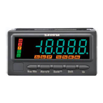
THERMOCOUPLE INPUT DIGITAL PANEL METER
(4-digit, LED display type)
Functions & Features
• 4-digit thermocouple input digital panel meter
• 1/8 DIN size
• Moving average function to suppress the display flickering
• Max. and Min. value display
• IP66 front panel
• Separable terminal block
• Rear terminal cover for safety strapped to the meter
96 (3.78)
48
(1.89)
Ma x/M in
Ala rm /
Init /
Sh ift
Up
MODEL: 47LT-1[1][2][3]-[4][5]
ORDERING INFORMATION
• Code number: 47LT-1[1][2][3]-[4][5]
Specify a code from below for each of [1] through [5].
(e.g. 47LT-101G-M2/Q)
• Specify the specification for option code /Q
(e.g. /C01/S01/SET)
INPUT – Field-selectable
1: (PR), K (CA), E (CRC), J (IC), T (CC), B (RH), R, S, N
[1] DC OUTPUT
0: Without
Current
A: 4 – 20 mA DC (Load resistance 550 Ω max.)
D: 0 – 20 mA DC (Load resistance 550 Ω max.)
Voltage
4: 0 – 10 V DC (Load resistance 10 kΩ min.)
5: 0 – 5 V DC (Load resistance 5000 Ω min.)
6: 1 – 5 V DC (Load resistance 5000 Ω min.)
4W: -10 – +10 V DC (Load resistance 10 kΩ min.)
[2] ALARM OUTPUT
0: None
1: N.O. relay contact, 4 points
2: SPDT relay contact, 2 points
https://www.m-system.co.jp/
98.5 (3.88)
mm (inch)
47LT SPECIFICATIONS
[3] DISPLAY COLOR
R: Red
YR: Orange
G: Green
BG: Bluegreen
B: Blue
W: White
[4] POWER INPUT
AC Power
M2: 100 – 240 V AC (Operational voltage range 85 – 264 V, 50/60 Hz)
DC Power
R: 24 V DC
(Operational voltage range 24 V ±10 %, ripple 10 %p-p max.)
P: 110 V DC
(Operational voltage range 85 – 150 V, ripple 10 %p-p max.)
[5] OPTIONS
blank: none
/Q: With options (specify the specification)
SPECIFICATIONS OF OPTION: Q (multiple selections)
COATING (For the detail, refer to M-System's web site.)
Moving parts and indicators are not coated.
/C01: Silicone coating
/C02: Polyurethane coating
/C03: Rubber coating
TERMINAL SCREW MATERIAL
/S01: Stainless steel
EX-FACTORY SETTING
/SET: Preset according to the Ordering Information Sheet
(No. ESU-9512)
GENERAL SPECIFICATIONS
Construction: Panel flush mounting
Degree of protection: IP66; applicable to the front of the
panel meter mounted according to the specified panel
cutout
Connection: M3 separable screw terminal (torque 0.6 N·m)
Screw terminal: Nickel-plated steel (standard) or stainless
steel
Housing material: Flame-resistant resin (gray)
Isolation: Input to DC output to HH output or H output to
L output or LL output to power
Burnout: Upscale standard; downscale optional by
programming
Linearization: Standard
Cold junction compensation: CJC sensor attached to the
input terminals
Setting: (Front button)
MODEL: 47LT
ES-9512 Rev.11 Page 1/8
Advertisement
Table of Contents

Related Manuals for M-system 47 Series


Summary of Contents for M-system 47 Series
- Page 1 /Q: With options (specify the specification) mm (inch) SPECIFICATIONS OF OPTION: Q (multiple selections) MODEL: 47LT-1[1][2][3]-[4][5] COATING (For the detail, refer to M-System's web site.) Moving parts and indicators are not coated. /C01: Silicone coating ORDERING INFORMATION /C02: Polyurethane coating •...
- Page 2 Input resistance: 1 MΩ minimum PERFORMANCE Burnout sensing: ≤ 0.1 μA Accuracy Default input type: K (CA) Display: ±1°C (or ±1.8°F) ±1 digit (PR, K, E, J, T) ±2°C (or ±3.6°F) ±1 digit (B, R, S, N) 47LT SPECIFICATIONS ES-9512 Rev.11 Page 2/8 https://www.m-system.co.jp/...
- Page 3 Input or DC output to alarm output to power: Reinforced insulation (300 V) Input to DC output: Basic insulation (300 V) RoHS Directive Protection against access to the terminal blocks: Finger protection (VDE 0660-514) 47LT SPECIFICATIONS ES-9512 Rev.11 Page 3/8 https://www.m-system.co.jp/...
- Page 4 Used to move on to the setting standby status and shift through display digits in each setting mode. Up button Used to choose setting value in each setting mode. Note: Refer to the operating manual for details on each function. 47LT SPECIFICATIONS ES-9512 Rev.11 Page 4/8 https://www.m-system.co.jp/...
- Page 5 98.5 (3.88) 96 (3.78) 12.5 (.49) 86 (3.39) 2 (.08) ■ REAR VIEW • Alarm Output • No Alarm Output 10–M3 SCREW 20–M3 SCREW TERMINAL TERMINAL 6.6 (.26) 2–M3 SCREW 4–M3 SCREW 91.5 (3.60) 47LT SPECIFICATIONS ES-9512 Rev.11 Page 5/8 https://www.m-system.co.jp/...
- Page 6 MODEL: 47LT MOUNTING REQUIREMENTS unit: mm + 0.8 – 0 min. 120 Panel thickness: 1.6 to 8.0 mm 47LT SPECIFICATIONS ES-9512 Rev.11 Page 6/8 https://www.m-system.co.jp/...
- Page 7 Loosen only the terminals 1 – 2 when connecting extension wires. Inductive Inductive Note: The section enclosed by broken line is only with Load (Coil) Load (Coil) DC output option. Diode, Varistor or Varistor or CR Circuit CR Circuit LOAD LOAD 47LT SPECIFICATIONS ES-9512 Rev.11 Page 7/8 https://www.m-system.co.jp/...
- Page 8 MODEL: 47LT Specifications are subject to change without notice. 47LT SPECIFICATIONS ES-9512 Rev.11 Page 8/8 https://www.m-system.co.jp/...
Need help?
Do you have a question about the 47 Series and is the answer not in the manual?
Questions and answers