M-system 47LV Operating Manual
Dc input digital panel meter 4 1/2 digit, led display type
Hide thumbs
Also See for 47LV:
- Specifications (7 pages) ,
- Operating manual (136 pages) ,
- Instruction manual (5 pages)
Table of Contents
Advertisement
Quick Links
OPERATING MANUAL
DC INPUT DIGITAL PANEL METER
(4 1/2 digit, LED display type)
BEFORE USE ....
Thank you for choosing M-System. Before use, please check
contents of the package you received as outlined below.
If you have any problems or questions with the product,
please contact M-System's Sales Office or representatives.
■ PACKAGE INCLUDES:
Digital panel meter ...................................................... (1)
Engineering unit sticker label sheet ........................... (1)
■ MODEL NO.
Confirm Model No. marking on the product to be exactly
what you ordered.
■ OPERATING MANUAL
This manual describes necessary points of caution when
you use this product, including installation, connection, ba-
sic maintenance procedures and detailed operations.
2.00 marked parameters are usable with the product ver-
sion 2.00 or higher.
POINTS OF CAUTION
■ CONFORMITY WITH EC DIRECTIVES
• This equipment is suitable for Pollution Degree 2 and In-
stallation Category II. Reinforced insulation (input or DC
output to alarm output to power: 300V) and basic insula-
tion (input to DC output: 300V) are maintained. Prior to
installation, check that the insulation class of this unit
satisfies the system requirements..
• Altitude up to 2000 meters
• The equipment must be installed such that appropriate
clearance and creepage distances are maintained to con-
form to CE requirements. Failure to observe these re-
quirements may invalidate the CE conformance.
• In order to enable the operator to turn off the power input
immediately, install a switch or a circuit breaker accord-
ing to the relevant requirements in IEC 60947-1 and IEC
60947-3 and properly indicate it.
■ POWER INPUT RATING & OPERATIONAL RANGE
Locate the power input rating marked on the product and
confirm its operational range as indicated below:
100 – 240V AC rating: 85 – 264V, 50/60 Hz, approx. 6.5VA
24V DC rating: 24V ±10%, approx. 3W
110V DC rating: 85 – 150V, approx. 3W
■ GENERAL PRECAUTIONS
• Before you remove the unit or mount it, turn off the power
supply and input signal for safety.
• Be sure to put the terminal cover on while the power is
supplied.
MODEL
■ ENVIRONMENT
• Indoor use
• When heavy dust or metal particles are present in the air,
install the unit inside proper housing with sufficient ven-
tilation.
• Do not install the unit where it is subjected to continuous
vibration. Do not subject the unit to physical impact.
• Environmental temperature must be within -10 to +55°C
(14 to 131°F) with relative humidity within 30 to 90% RH
in order to ensure adequate life span and operation.
• Be sure that the ventilation slits are not covered with ca-
bles, etc.
■ REQUIREMENTS TO ENSURE IP 66
• Observe the designated panel cutout size (W92 × H45
mm).
• The watertight packing included in the product package
must be placed behind the front cover.
• Both mounting brackets must be fastened tightly until
they hit the panel.
• Confirm visually that the packing is not contorted or ex-
cessively run off the edge after installation.
■ WIRING
• Make sure for safety that only qualified personnel per-
form the wiring.
• Do not install cables (power supply, input and output)
close to noise sources (high frequency line, etc.).
• Do not bind these cables together with those in which
noises are present. Do not install them in the same duct.
■ AND ....
The unit is designed to function as soon as power is sup-
plied, however, a warm up for 10 minutes is required for sat-
isfying complete performance described in the data sheet.
47LV
47LV
EM-9502-B Rev.3
P. 1 / 18
Advertisement
Table of Contents

Related Manuals for M-system 47LV


Summary of Contents for M-system 47LV
- Page 1 • Indoor use • When heavy dust or metal particles are present in the air, Thank you for choosing M-System. Before use, please check install the unit inside proper housing with sufficient ven- contents of the package you received as outlined below.
-
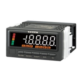
Page 2: Component Identification
47LV COMPONENT IDENTIFICATION n TOP VIEW Strap Specifications Watertight Sealing n FRONT VIEW n SIDE VIEW Mounting Bracket Terminal Cover (1) Main Display (2) Alarm Indicators Spn D/P Min Max (3) Function Indicators Max/Min Alarm/ Scale/ Shift (8) Up Button... -
Page 3: Installation
47LV INSTALLATION ■ HOW TO MOUNT THE UNIT ON A PANEL ■ PANEL CUTOUT unit: mm The watertight packing must be in place to hold the meter. + 0.8 – 0 Do not remove it. 1) Insert the unit into the panel cutout. - Page 4 47LV ■ CONNECTION DIAGRAM ALARM SUFFIX CODE 0: No alarm output • Input code: 1, 2 • Input code: 3 • Input code: 4 • Input code : 5, 6 DC OUTPUT – INPUT U(+) POWER V(–) COM – COM –...
-
Page 5: Setting Procedure
47LV SETTING PROCEDURE INITIAL SETTING FLOWCHART POWER ON Hold down Scale/ button for 3 seconds or more to move on to Scaling Setting Mode. Choose an input type and display scale values. Hold down Alarm/ button for 3 seconds or more to move on to Alarm Setting Mode. - Page 6 47LV ■ OPERATIONS IN MEASURING MODE • Switching the main display to MAX or MIN values Press Max/Min button to switch the main display to MAX or MIN values. ‘Max’ or ‘Min’ indicator turns on during the MAX/MIN display mode.
- Page 7 47LV ■ OPERATIONS IN SETTING MODES • Main display The main display shows the current settings while the panel meter is in the setting mode. • Shifting through setting parameters In any setting mode, pressing Alarm/ button shifts one parameter to the next. Pressing Scale/ button shifts one to the previous.
- Page 8 47LV ■ SCALING SETTING MODE Measuring Mode Hold down Scale/ button Hold down Alarm/ or Scale/ button for ≥3 seconds for ≥1 second Scaling Setting Mode Setting Parameters Scale/ Set value Shift Input Type Scale/ Alarm/ Scale/ Alarm/ Scale/ Set value...
- Page 9 47LV PARAMETER INDICATORS DISPLAY FUNCTION DEFAULT VALUE Measuring range -10 to +10V Input type Measuring range -5 to +5V Measuring range 0 to 5V Measuring range 1 to 5V Measuring range 0 to 20mA Measuring range 4 to 20mA Measuring range -1 to +1V...
- Page 10 47LV DEFAULT PARAMETER INDICATORS DISPLAY FUNCTION VALUE Decimal point position 2.00) 4 positions or none Decimal point position (10 –4 Analog output Proportional to the display value 2.00 function mode Proportional to the scaling value Analog output 0% (increasing) Analog output 0% adjustment:...
- Page 11 47LV ■ ALARM SETTING MODE Measuring Mode Hold down Alarm/ button Hold down Alarm/ or Scale/ button for ≥3 seconds for ≥1 second Alarm Setting Mode Setting Parameters Scale/ Set value Shift 2 / 4* Alarm Point Alarm/ Scale/ Alarm/...
- Page 12 47LV Alarm/ Scale/ Alarm/ Scale/ Shift -19999...19999 H Setpoint Alarm/ Scale/ Alarm/ Scale/ Shift LMHI / LMLO H Trip Action Alarm/ Scale/ Alarm/ Scale/ Shift 0000...9999 H Deadband Alarm/ Scale/ Alarm/ Scale/ Shift 00...99 H ON Delay Time Alarm/ Scale/...
- Page 13 47LV DEFAULT PARAMETER INDICATORS DISPLAY FUNCTION VALUE Dual alarm: L, H Alarm points Quad alarm: LL, L, H, HH LL setpoint* LL: Setpoint value 2.00 2.00 LL: Hi trip LL trip action LL: Lo trip LL deadband (hysteresis) LL: Deadband (hysteresis) value 2.00...
- Page 14 47LV DEFAULT PARAMETER INDICATORS DISPLAY FUNCTION VALUE HH setpoint* HH: Setpoint value 2.00 HH trip action 2.00 HH: Hi trip HH: Lo trip HH deadband (hysteresis) HH: Deadband (hysteresis) value 2.00 HH: ON delay time (seconds) HH ON delay time 2.00...
- Page 15 47LV • Alarm output pattern Alarm trips according to the setpoint and the trip action (direction) setting. P indicator turns on when all other alarm indicators are off. [Example] Typical LL / L / H / HH trip setting [Example] All trip points set to High setting...
- Page 16 47LV DEFAULT PARAMETER INDICATORS DISPLAY FUNCTION VALUE No moving averaging Moving average Moving average with 2 samples Moving average with 4 samples Moving average with 8 samples 2.00 Moving average with 16 samples 2.00 Moving average with 32 samples Moving average with 64 samples 2.00...
- Page 17 47LV ■ LOCKOUT SETTING MODE Measuring Mode Hold down Alarm/ + Max/Min button Hold down Alarm/ or Scale/ button at once for a preset time* for ≥1 second Lockout Setting Mode Setting Parameters Set value Shift OFF / ON Alarm Setting Lockout...
-
Page 18: Error Messages
M-System’s option, the repair, replacement or refund of the purchase price of any M-System product which is defective under the terms of this warranty. To submit a claim under this warranty, the purchaser must return, at its expense, the defective M-System product to the below address together with a copy of its original sales invoice.
Need help?
Do you have a question about the 47LV and is the answer not in the manual?
Questions and answers
Dear Sir/Madam My name Nida from Indonesia Do you sell Ampere Meter M-System 47LV-200R-M2 ? I need 2 pcs Please confirm my inquiry Thank you