Table of Contents
Advertisement
Quick Links
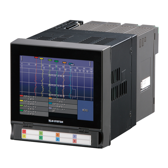
73VR3100 PAPERLESS RECORDER
STARTUP GUIDE
- Read Before Installation -
1.
POINTS OF CAUTION ...................................................................... 2
2.
PACKAGE INCLUDES... .................................................................... 5
3.
ITEMS TO PREPARE........................................................................ 6
4.
COMPONENT IDENTIFICATION ........................................................... 7
5.
EXTERNAL DIMENSIONS .................................................................. 9
6.
INSTALLING THE UNIT .................................................................... 10
7.
WIRING TO THE UNIT ..................................................................... 12
8.
SETTING UP THE RECORDER ............................................................ 13
9.
LET'S START RECORDING ............................................................... 20
10. MORE ABOUT THE 73VR3100 ........................................................... 23
Contents
- 1 -
EM-7397-A Rev.9
Advertisement
Table of Contents

Subscribe to Our Youtube Channel
Related Manuals for M-system 73VR3100


Summary of Contents for M-system 73VR3100
-
Page 1: Table Of Contents
COMPONENT IDENTIFICATION ............7 EXTERNAL DIMENSIONS ..............9 INSTALLING THE UNIT ..............10 WIRING TO THE UNIT ..............12 SETTING UP THE RECORDER ............13 LET’S START RECORDING ............... 20 10. MORE ABOUT THE 73VR3100 ............23 – 1 – EM-7397-A Rev.9... -
Page 2: Points Of Caution
POINTS OF CAUTION Thank you for choosing M-System. Before use, please read this manual carefully. If you have any problems or questions with the product, please contact M-System’s Sales Office or representatives. This product is for use in general industrial environments, therefore may not be suitable for applications which require higher level of safety (e.g. - Page 3 • Do not store or use the 73VR3100 in environments subject to chemical evaporation (such as that of organic solvents), or where there are chemicals and/or acids present in the air. • Do not use paint thinner or organic solvents to clean the 73VR3100. • Observe the environmental conditions when using the 73VR3100. • Wait at least for 5 seconds before turning on the power supply after it has been turned off. The 73VR3100 may not start up if the time interval is less than 5 seconds. n ENVIRONMENT • Indoor use • The 73VR3100 is designed to be mounted on a vertical panel. It is not suitable for a slanted or a horizontal panel surface. • Environmental temperature must be within 0 to 50°C (32 to 122°F) with relative humidity within 30 to 85% RH in order to ensure adequate life span and operation. • Desktop type cannot be mounted on a panel surface. • The handle and rubber feet cannot be detached from desktop type unit. n GROUNDING • Be sure to determine in advance the most stable grounding point in the environment and earth the 73VR3100’s FG terminal and that of connected devices (PC) to it in or- der to prevent electric shock to the operator and to protect the devices from dielectric breakdown.
- Page 4 - The color displayed on the LCD screen may appear different when seen from outside the specified viewing angle. - When the same image is displayed on the screen for a long time period, an afterim- age may appear when the image is changed. If this happens, turn off the 73VR3100 and wait 10 seconds before restarting it. • To prevent an afterimage: - Set the screensaver when you plan to display the same image for a long time pe- riod.
-
Page 5: Package Includes
PACKAGE INCLUDES... Please confirm that all items mentioned below are included in the package. Paperless Recorder I/O module (R3-x) instruction manual Mounting bracket (two pieces) Startup guide (this booklet) Not included for desktop type. Software CD (73VRPAC2) – 5 –... -
Page 6: Items To Prepare
ITEMS TO PREPARE • CF card Prepare one of the following model numbers: 1. Manufacturer: Hagiwara Solutions Model No.: MCF10P-xxxxS (Alternative model: CFI-xxxxDG) Capacity: 128 MB through 1 GB 2. Manufacturer: Apacer Technology Model name: CFC III Model No.: AP-CFxxxxE3ER-ETNDNRK Parts No.: 256 MB ... 81.2A010.1H34C 512 MB ... 81.2B010.1H34C 1 GB ... 81.2E010.1H34C Model No.: AP-CFxxxxE3ER-ETNDNR Parts No.: 256 MB ... 81.2A010.1H10C 512 MB ... 81.2B010.1H10C 1 GB ... 81.2E010.1H10C Capacity: 256 MB through 1 GB • CF card reader The CF card reader is required to read the card contents into a PC. • Refer to Users Manuals stored in the 73VRPAC2 CD-R for detailed operations of the 73VR3100. (1) Paperless Recorder (model: 73VR3100) Users Manual ....No. EM-7397-B (2) PC Configurator Software (model: 73VR31BLD) Users Manual ..No. EM-7397-C – 6 –... -
Page 7: Component Identification
(3) CF Card Slot (4) Eject Button Used to retrieve the CF Card. (5) Reset Button Used to restart the 73VR3100. (6) CF Card Access Indicator LED Red light turns on during the CF Card is accessed. (7) USB Connector Connect an USB flash-memory. - Page 8 I REAR VIEW (8) PC Configurator Port • With I/O Modules • Without I/O Modules (9) LAN Port (7) USB Connector (10) I/O Data Allocation DIP SW (11) Power LED (12) Power Input Terminal Block • I/O Module Assignment (8) PC Configurator Port Used to program with the R3 Configurator Software.
-
Page 9: External Dimensions
EXTERNAL DIMENSIONS Unit: mm (inch) · Panel mount type 135.5 (5.33) 151.5 (5.96) 245.1 (9.65) 144 (5.67) 29.5 2 – 26 (.08 – 1.02) (1.16) (panel thickness) Attach the mounting bracket either on the top/bottom or on the sides. – 9 –... - Page 10 · Desktop type 135.5 (5.33) 144 (5.67) 245.1 (9.65) 29.5 (1.16) The handle and rubber feet cannot be detached from desktop type unit. – 10 –...
-
Page 11: Installing The Unit
1434 (114 × n) – 6 Notes 1. The R3 I/O modules mounted on the second and the third 73VR3100 from the top cannot be removed in the vertical clustered mounting. 2. Dimensional tolerance ±3% unless otherwise specified. (±0.3 mm for <10 mm) 3. - Page 12 PANEL MOUNTING (1) Insert the 73VR3100 from the front side of the panel. (2) Remote the sheets covering the mounting bracket holes. Fix two mounting brackets either on the sides or on the top and bottom of the unit. Tighten screws.
-
Page 13: Wiring To The Unit
WIRING TO THE UNIT Before setting up the Paperless Recorder, connect power supply cables to the unit. n WIRE TYPE Please choose appropriate wires referring to the following conditions: • Terminal type: Euro type connector terminal • Wire diameter: 0.14 to 1.5 mm or AWG26 to 16 • Core wire type: Stranded or Single core (For stranded wires, use pin terminals.) • Exposed wire length: 10 mm n CONNECTING TO POWER SOURCE • Confirm the power input rating on the specification label. Rated Voltage Operational Voltage Range Power Consumption AC Power 100 – 240V AC 85 – 264V AC Approx. 27VA at 100V Approx. 46VA at 240V DC Power 24V DC... -
Page 14: Setting Up The Recorder
SETTING UP THE RECORDER Basic setup procedure is explained in this section, using an example of the following in- put modules to store data in a CF card in 1 second storing interval. Module Slot No. 1 Model R3-SS4S DC current input module Module Slot No. 2 Model R3-DA16S Discrete input module I/O DATA ALLOCATION DIP SWITCH The DIP switch (See Section 4) setting is used to assign required data area for each I/O module. Four (4) modes (1, 4, 8 and 16) are selectable depending upon the number of I/Os as in the table below. (1) Turn off the power supply to the unit. (2) Set DIP switch positions as indicated below: Module Slot No. 1 = Data Area 4 (SW1 = ON, SW2 = OFF) Module Slot No. 4 = Data Area 1 (SW4 = OFF) - Page 15 INSTALLING PC CONFIGURATOR SOFTWARE The 73VR3100 software package 73VRPAC2 includes a PC Configurator Software (model: 73VR31BLD) to help you easily set up the 73VR3100. (1) Start up the WIndows PC and insert the 73VRPAC2 CD. (2) After you have specified to install the 73VR31BLD, InstallShield window automati- cally appears on the screen. (3) Follow the step-by-step the instructions that will appear on the window.
- Page 16 CREATING A CONFIGURATION FILE ON THE 73VR31BLD Let us show you an example to creating a setting data for the following input modules and specifications. • I/O modules Module Slot No. 1: Model R3-SS4S (input range: 4 – 20mA, scale: 0 – 100°C) Module Slot No. 2: Model R3-DA16S • Storing interval: 1 second • Storing mode: Normal Recording is manually initiated and stopped. Data is continuously stored while the recording is on. • Input 1: Module Slot No. 1, Channel 1 • Input 2: Module Slot No. 2, Channel 1 n STARTING UP THE 73VR31BLD Go to Programs > 73VR > 73VR31BLD > 73VR31BLD_Vxxx to start the program.
- Page 17 n BASIC SETTING The figure below shows an initial view of the 73VR31BLD. Specify the following setting items: (1) System Operating mode: Normal (2) Data storing method Storing interval: 1 sec Storing setting: Normal (3) Input pen setting (Individual) – 17 –...
- Page 18 n INPUT 1 PEN SETTING Specify the following setting items: (1) Common setting Enable / Disable: Enable Analog / Discrete: Analog Channel No.: 1 Tag: INPUT 01 Unit: deg C (2) Detail setting Analog type: 0 to 100 percent Input range (L, H): 0.0 to 100.0 Eng. range (L, H): 0.0 to 100.0 Plot range (L, H): 0.0 to 100.0 Scale shift: 0 Normal / Logarithmic: Normal (3) Press [ > ] button to the right of [ Input 1 ] button to go to Input 2. ☛ See 73VR31BLD Users Manual Section 2 for detail. – 18 –...
- Page 19 n INPUT 2 PEN SETTING Specify the following setting items: (1) Common setting Enable / Disable: Enable Analog / Discrete: Discrete Channel No.: 65 Tag: INPUT 02 (2) Press [ > ] button to the right of [ Input 2 ] button to go to Input 2. NOTE – How to Count Channel No.? – Channel 1 of the Slot No. 2 module is assigned to that of Input 2. Slot No. 2 module, model R3-DA16S, is a discrete input module. Slot No. 1 module, model R3-SS4S, is an analog input module with Data Allocation Mode When you count how many channels are assigned to Slot No. 1 in order to assign the channels for Slot No. 2, it is calculated as: Data Allocation Mode for Slot No. 1 x 16 = 4 x 16 = 64. Then the Slot No. 2 starts at Channel 65. ☛ See 73VR31BLD Users Manual Section 2 for detail. – 19 –...
- Page 20 n INPUT 3 THROUGH INPUT 8 PEN SETTING Disable Input 3 through Input 8: (1) Common setting Enable / Disable: Disable (2) Press [ OK ] button to go back to the initial view. Basic setting using the PC Configurator Software is now complete. n SAVING CONFIGURATION FILE Save the configuration as a file in the CF card. (1) Press [ Write setting file ] under ‘File operation’ to call up ‘Save as’ window. (2) Locate the CF card and specify ‘73VR.VRP31’ as a file name, and click [ OK ]. (3) Click [ Close ] on the initial window or click [ X ] button on the title bar to quit the pro- gram. – 20 –...
-
Page 21: Let's Start Recording
LET’S START RECORDING READING IN SETTING FILE The setting file created on the 73VR31BLD is read into the 73VR3100 via the CF card. n INSERTING THE CF CARD (1) Turn off the power supply to the 73VR3100. (2) Open the front cover. (3) Insert the CF card so that its side without label is on the top. CF Card (4) Push it in until EJECT button is popped up. (5) Close the front cover. NOTES – Hot to Take the CF Card Out –... - Page 22 STARTING THE 73VR3100 (1) Turn on the power supply to the 73VR3100. NOTE The 73VR3100 creates files necessary for its operation in the CF card after its power sup- ply has been turned on. This operation may take some time. ☛ See 73VR3100 Users Manual Section 7 for detail. (2) Touch [ MENU ] on the Record view to show the menu keys. (3) Touch [ Start ] to start recording. – 22 –...
- Page 23 CONFIRMING DATA WITH SIMULATED INPUT (1) Connect a current signal simulator (e.g. M- System model C-HCL-A) to the input termi- nals (1 – 2) of the Slot No. 1 module (R3- SS4S). – Current Simulator R3-SS4 (2) Apply 12 mA and confirm that the recorder shows 50°C on the screen. (3) Apply a contact input signal to the Ch. 1 terminals of the Slot No. 2 module (R3- DA16S) and confirm that the recorder shows ON and OFF status according to the simulated input.
-
Page 24: 10. More About The 73Vr3100
10. MORE ABOUT THE 73VR3100 10.1 SETUP ON THE 73VR3100 VIEW The 73VR3100 can be configured via the front menu keys, without using the PC Configu- rator software. (1) Insert the CF card into the 73VR3100. (2) Turn on the power supply to the 73VR3100. (3) Touch [ MENU ] key on the screen to call up con- trol buttons. (4) Touch [ Config. ] key. (5) Select a menu item to start setting. ☛ See 73VR3100 Users Manual Section 4 for detail. – 24 –... - Page 25 10.2 DISPLAY VIEWS The 73VR3100 is available with: • ‘Trend View,’ ‘Overview’ and ‘Bargraph View’ plotting recorded data in real time. • ‘Retrieve View’ and ‘ A larm History’ showing data stored in the CF card. ☛ See 73VR3100 Users Manual Section 6 for detail. Trend View Overview Bargraph – 25 –...
Need help?
Do you have a question about the 73VR3100 and is the answer not in the manual?
Questions and answers