M-system 47DV Series Manual
Dc input digital panel meter
Hide thumbs
Also See for 47DV Series:
- Operating manual (34 pages) ,
- Operating manual (254 pages) ,
- Instruction manual (8 pages)
Table of Contents
Advertisement
Quick Links
Digital Panel Meters 47 Series
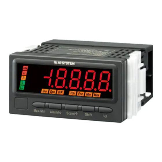
DC INPUT DIGITAL PANEL METER
(5½ digit, LCD display type)
Functions & Features
• 5 1/2 digit DC input digital panel meter
• Scaling range -20000 to 100000
• 1/8 DIN size
• Display color can be changed at alarm
• Bargraph indicator shows approximate measuring status
• 12 V or 24 V excitation supply
• External event trigger input
• RS-485 / Modbus RTU output
• Infrared interface
• BCD output
• Loop test output (DC output option)
• IP66 front panel
• Separable terminal block
• Safety terminal cover tethered to the device with a strap
96 (3.78)
48
(1.89)
Ma x/M in
Ala rm /
Sc ale /
Sh ift
Up
MODEL: 47DV-[1][2][3][4]-[5][6]
ORDERING INFORMATION
• Code number: 47DV-[1][2][3][4]-[5][6]
Specify a code from below for each of [1] through [6].
(e.g. 47DV-1111-M2/Q)
• Specify the specification for option code /Q
(e.g. /C01/S01/SET)
[1] INPUT
1: DC voltage
2: DC current
[2] DC OUTPUT
0: Without
1: With
[3] EXCITATION SUPPLY
1: +12 V sensor excitation
2: +24 V two-wire transmitter excitation
http://www.m-system.co.jp/
98.5 (3.88)
mm (inch)
47DV SPECIFICATIONS
[4] I/O OPTIONS
0: None
1: Alarm output: N.O. relay, 4 points
2: Alarm output: SPDT relay, 2 points
3: Alarm output: N.O. photo MOSFET relay, 4 points
(CE not available)
4: Network interface: RS-485 / Modbus RTU
5: BCD output
6: Event trigger input
7: Alarm output: N.O. relay, 4 points
+ Network interface: RS-485 / Modbus RTU
8: Alarm output: SPDT relay, 2 points +
Network interface: RS-485 / Modbus RTU
9: Alarm output: N.O. photo MOSFET relay, 4 points + BCD output
(CE not available)
A: Event trigger input + BCD output
[5] POWER INPUT
AC Power
M2: 100 – 240 V AC (Operational voltage range 85 – 264 V, 50/60 Hz)
DC Power
R: 24 V DC
(Operational voltage range 24 V ±10 %, ripple 10 %p-p max.)
P: 110 V DC
(Operational voltage range 85 – 150 V, ripple 10 %p-p max.)
[6] OPTIONS
blank: none
/Q: With options (specify the specification)
SPECIFICATIONS OF OPTION: Q (multiple selections)
COATING (For the detail, refer to M-System's web site.)
Moving parts and indicators are not coated.
/C01: Silicone coating
/C02: Polyurethane coating
/C03: Rubber coating
TERMINAL SCREW MATERIAL
/S01: Stainless steel
EX-FACTORY SETTING
/SET: Preset according to the Ordering Information Sheet
(No. ESU-9501)
RELATED PRODUCTS
• Resistor module (model: REM2-250)
• Connector terminal block (model: CNT)
• Special cable (model: HDR40)
• Infrared Communication Adaptor (model: COP-IRU)
• PC configurator software (model: 47DCFG)
Downloadable at M-System's web site.
MODEL: 47DV
ES-9501 Rev.16 Page 1/13
Advertisement
Table of Contents

Subscribe to Our Youtube Channel
Related Manuals for M-system 47DV Series


Summary of Contents for M-system 47DV Series
- Page 1 (inch) /Q: With options (specify the specification) MODEL: 47DV-[1][2][3][4]-[5][6] SPECIFICATIONS OF OPTION: Q (multiple selections) COATING (For the detail, refer to M-System's web site.) ORDERING INFORMATION Moving parts and indicators are not coated. • Code number: 47DV-[1][2][3][4]-[5][6] /C01: Silicone coating Specify a code from below for each of [1] through [6].
-
Page 2: General Specifications
Current rating: ≤ 22 mA DC position depending upon setting). ‘S.ERR’ (main display) • Shortcircuit Protection and ‘UNDER’ or ‘OVER’ (sub display) blinking when the input Current limited: 30 mA max. signal is out of the usable range. 47DV SPECIFICATIONS ES-9501 Rev.16 Page 2/13 http://www.m-system.co.jp/... -
Page 3: Input Specifications
DATA (Do 11...Do 68): BCD Output data in 6 digits The device is reset when RESET signal is turned on. Do 1x = LSD ... Do 6x = 6th LSD ■ Alarm Output: Relay contact 47DV SPECIFICATIONS ES-9501 Rev.16 Page 3/13 http://www.m-system.co.jp/... -
Page 4: Standards And Approvals
Dielectric strength: 2000 V AC @ 1 minute (input or excitation supply to DC output to HH output or H output to L output or LL output to network or BCD output or event trigger input to power to ground) 47DV SPECIFICATIONS ES-9501 Rev.16 Page 4/13 http://www.m-system.co.jp/... -
Page 5: External View
47Dx 47Dx RS-232-C *1. Internal terminating resistor is used when the device is at the end of a transmission line. *2. Install shield cables to all sections and ground them at single point. 47DV SPECIFICATIONS ES-9501 Rev.16 Page 5/13 http://www.m-system.co.jp/... - Page 6 6.6 (.26) 2–M3 SCREW 4–M3 SCREW 91.5 (3.60) • BCD Output, Event Trigger Input, Alarm Output (Photo MOSFET Relay) 10–M3 SCREW TERMINAL 2–M3 SCREW 14 15 16 EURO TYPE 50-pin CONNECTOR CONNECTOR TERMINAL 47DV SPECIFICATIONS ES-9501 Rev.16 Page 6/13 http://www.m-system.co.jp/...
- Page 7 MODEL: 47DV MOUNTING REQUIREMENTS unit: mm + 0.8 – 0 min. 120 Panel thickness: 1.6 to 8.0 mm 47DV SPECIFICATIONS ES-9501 Rev.16 Page 7/13 http://www.m-system.co.jp/...
- Page 8 Terminals with insulation sleeve do not fit. Applicable wire wize 0.3 to 1.25 mm V3/I3 3 max 4 min sensor output REM2 3.2 dia. – – sensor excitation +12V – – 12 max 47DV SPECIFICATIONS ES-9501 Rev.16 Page 8/13 http://www.m-system.co.jp/...
- Page 9 *1. When the device is located at the end of a transmission line via twisted-pair cable (when there is no cross-wiring), close across the terminal 12 – 13 with a leadwire. When the device is not at the end, no shortcircuit wire is required. 47DV SPECIFICATIONS ES-9501 Rev.16 Page 9/13 http://www.m-system.co.jp/...
- Page 10 Do12 1st LSD Do14 Do18 (polarity +, –) Digital Display Use Special cable (model: HDR40) and Connector Terminal Block (polarity +, –) (model: CNT). Refer to the cable’s data sheet for pin assignments. 47DV SPECIFICATIONS ES-9501 Rev.16 Page 10/13 http://www.m-system.co.jp/...
- Page 11 L OUTPUT ZERO LL OUTPUT Lc, LLc Connection Example TIMING : 11 S-TMR : 12 +6 V HOLD : 13 RESET : 14 ZERO : 15 2 kΩ 1.5 kΩ open contact collector 47DV SPECIFICATIONS ES-9501 Rev.16 Page 11/13 http://www.m-system.co.jp/...
-
Page 12: Viewing Angle
*1. DATA includes BCD Output, POL, OVF, HH, H, P, L, LL and RUN. *2. Wait for at least 20 ms between DAV turning off and the next REQ signal. REQ 1 47Dx REQ 2 47Dx REQ 3 47Dx 47DV SPECIFICATIONS ES-9501 Rev.16 Page 12/13 http://www.m-system.co.jp/... -
Page 13: System Configuration Examples
MDP-4R) * or MDP-4R) * Digital Panel Meter Digital Panel Meter (model: 47Dx) (model: 47Dx) *1. Insert lightning surge protectors recommended in this example if necessary. Specifications are subject to change without notice. 47DV SPECIFICATIONS ES-9501 Rev.16 Page 13/13 http://www.m-system.co.jp/...
Need help?
Do you have a question about the 47DV Series and is the answer not in the manual?
Questions and answers