
Related Manuals for Honeywell 2MLF-AV8A


Summary of Contents for Honeywell 2MLF-AV8A
- Page 1 Honeywell Process Solutions Analog Input Module 2MLF-AV8A, AC8A User's Guide ML200-AI R200 September 2010 Release 200 Honeywell...
- Page 2 In no event is Honeywell liable to anyone for any indirect, special or consequential damages. The information and specifications in this document are subject to change without notice.
- Page 3 About This Document This document describes the procedure to install and configure the 2MLF-AV8A and AC8A; Analog to digital voltage and current converters. Release Information Document Name Document Release Publication Number Date 2MLF-AV8A, AC8A User's Guide ML200-AI September 2010 References The following list identifies all documents that may be source of reference for material discussed in this publication.
- Page 4 Honeywell Global TAC – India Phone: +91-20- 6603-9400 Fascimile: +91-20- 6603-9800 Mail: Honeywell Automation India Ltd 56 and 57, Hadapsar Industrial Estate Hadapsar, Pune –411 013, India Email: Global-TAC-India@honeywell.com Korea Analog Input Module 2MLF-AV8A, AC8A User's Guide R200 Honeywell September 2010...
- Page 5 +886-7-536-2039 Mail: Honeywell Taiwan Ltd. 17F-1, No. 260, Jhongshan 2nd Road. Cianjhen District Kaohsiung, Taiwan, ROC Email: Global-TAC-Taiwan@honeywell.com Japan Contact: Honeywell Global TAC – Japan Phone: +81-3-6730-7160 Fascimile: +81-3-6730-7228 R200 Analog Input Module 2MLF-AV8A, AC8A User's Guide September 2010 Honeywell...
- Page 6 20th Floor, 1-16-1 Kaigan, Minato-ku, Tokyo 105-0022, Japan Email: Global-TAC-JapanJA25@honeywell.com Elsewhere Call your nearest Honeywell office. World Wide Web Honeywell Solution Support Online: http://www.honeywell.com/ps Training Classes Honeywell Automation College: http://www.automationcollege.com Analog Input Module 2MLF-AV8A, AC8A User's Guide R200 Honeywell September 2010...
- Page 7 WARNING, Risk of electrical shock: Potential shock hazard where HAZARDOUS LIVE voltages greater than 30 Vrms, 42.4 Vpeak, or 60 VDC may be accessible. R200 Analog Input Module 2MLF-AV8A, AC8A User's Guide September 2010 Honeywell...
- Page 8 Chassis Ground: Identifies a connection to the chassis or frame of the equipment shall be bonded to Protective Earth at the source of supply in accordance with national and local electrical code requirements. viii Analog Input Module 2MLF-AV8A, AC8A User's Guide R200 Honeywell September 2010...
-
Page 9: Table Of Contents
Installation environment ....................... 47 Handling precautions ......................48 Wiring ......................49 Precautions for wiring ......................49 Wiring examples ........................49 OPERATING PROCEDURES AND MONITORING ..... 53 Operating procedures ................... 53 R200 Analog Input Module 2MLF-AV8A, AC8A User's Guide September 2010 Honeywell... - Page 10 Example using PUT/GET instruction ................... 94 Output data range setting ....................97 PROGRAMMING ............... 107 Read/Write of operation parameter settings area ........107 Read operation parameters settings area (GET, GETP command) ........107 Analog Input Module 2MLF-AV8A, AC8A User's Guide R200 Honeywell September 2010...
- Page 11 Status check of A/D conversion module using System Monitor menu ....... 134 APPENDIX ................. 135 Appendix 1: Terminology ................135 Appendix 2: External dimensions ............. 138 External dimensions of 2MLF-AV8A/AC8A ................ 138 R200 Analog Input Module 2MLF-AV8A, AC8A User's Guide September 2010 Honeywell...
- Page 12 Table 5 – I/O area of A/D converted data ..............69 Table 6 – Setting area of run parameters ..............71 Table 7 – List of error codes ..................129 Analog Input Module 2MLF-AV8A, AC8A User's Guide R200 Honeywell September 2010...
- Page 13 Figure 5 – Characteristics of A/D conversion (voltage input) ........19 Figure 6 – Characteristics of A/D conversion (current input) ......... 20 Figure 7 – Parts of 2MLF-AV8A and 2MLF-AC8A ............24 Figure 8 – Accuracy ....................... 38 Figure 9 – Operating procedure ..................53 Figure 10 –Program example with variables and addresses ........
- Page 14 Contents Figures Analog Input Module 2MLF-AV8A, AC8A User's Guide R200 Honeywell September 2010...
-
Page 15: Introduction
1. Introduction Overview This user’s guide describes two analog input modules. 2MLF-AV8A type voltage to digital conversion module • 2MLF-AC8A type current to digital conversion module. • Both A/D conversion modules are used for converting analog signals (voltage or current input) from PLC’s external device to signed 16-bit binary data of digital value. - Page 16 1. Introduction 1.2. Features Detecting input signal failure/disconnect: Applicable only when analog input range of 1 ~ 5V (or 4 ~ 20mA) is used. Analog Input Module 2MLF-AV8A, AC8A User's Guide R200 Honeywell September 2010...
-
Page 17: Terminology
In a digital electronic circuit, data is processed and saved in the form of numbers 0 and 1 only. The data is processed as a string of 0s and 1s. For example, ON and OFF signals R200 Analog Input Module 2MLF-AV8A, AC8A User's Guide September 2010 Honeywell... -
Page 18: Figure 3 - Digital Value
This is done using Analog to Digital converter (A/D conversion module). Similarly, to get an analog output from a digital value, a Digital to Analog converter (D/A conversion module) is used. Analog Input Module 2MLF-AV8A, AC8A User's Guide R200 Honeywell... -
Page 19: Characteristics Of A/D Conversion
0mA of analog input corresponds to the output of digital value of 0. Analog input of 20mA corresponds to the output digital value of 16000. This means analog input of 1.25µA represents digital value of 1 (Figure 6). R200 Analog Input Module 2MLF-AV8A, AC8A User's Guide September 2010 Honeywell... -
Page 20: Figure 6 - Characteristics Of A/D Conversion (Current Input)
1. Introduction 1.3. Terminology Figure 6 – Characteristics of A/D conversion (current input) Analog Input Module 2MLF-AV8A, AC8A User's Guide R200 Honeywell September 2010... -
Page 21: Specifications
0 ~ 10000 -10000 ~ 10000 Digital value Percentile value 0 ~ 10000 (2) Current Type Analog input 4 ~ 20mA 0 ~ 20mA Digital value Unsigned value 0 ~ 16000 R200 Analog Input Module 2MLF-AV8A, AC8A User's Guide September 2010 Honeywell... - Page 22 Photo-coupler isolation between input terminal and PLC power (no isolation between Isolation method channels) Terminal 18-point terminal connected I/O addresses Fixed type: 64 points, Variable type: 16 points assigned Analog Input Module 2MLF-AV8A, AC8A User's Guide R200 Honeywell September 2010...
- Page 23 Offset Value: Analog input value when digital output value is 0 with digital output format set to unsigned value. • Gain Value: Analog input value when digital output value is 16000 with digital output format set to unsigned value. R200 Analog Input Module 2MLF-AV8A, AC8A User's Guide September 2010 Honeywell...
-
Page 24: Part Names And Functions
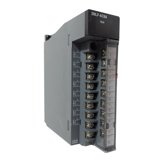
2. Specifications 2.2. Part names and functions Part names and functions The following example illustrates the parts of 2MLF-AV8A and 2MLF-AC8A modules respectively. Figure 7 – Parts of 2MLF-AV8A and 2MLF-AC8A Analog Input Module 2MLF-AV8A, AC8A User's Guide R200 Honeywell... -
Page 25: Table 2 - Led Indications
Displays the operation status of 2MLF-AV8A/2MLF-AC8A On: Operation normal • Flickering: Error occurs (For more details, refer to section Error codes) • Off: DC 5V disconnected, 2MLF-AV8A/2MLF-AC8A module error • Terminal Analog input terminal, whose respective channels can be connected with external devices. -
Page 26: Characteristics Of I/O Conversion
Characteristics of I/O conversion is a straight line plotted between the Offset and Gain values when converting analog signal (voltage or current input) from PLC’s external device to digital value. I/O conversion characteristics of A/D conversion modules are as follows. Analog Input Module 2MLF-AV8A, AC8A User's Guide R200 Honeywell September 2010... -
Page 27: I/O Characteristics Of 2Mlf-Av8A
2.3. Characteristics of I/O conversion I/O characteristics of 2MLF-AV8A 2MLF-AV8A is a module exclusively used for 8-channel analog voltage input. The input range can be set from user program or special module package for respective channels. Output formats of digital data are as specified below: Unsigned value •... - Page 28 The digital output value for voltage input characteristics is as specified below: (Resolution (based on 1/16000): 0.25mV) On the I/O Parameters Setting window, set Input Range to 1 ~ 5V. Analog Input Module 2MLF-AV8A, AC8A User's Guide R200 Honeywell September 2010...
- Page 29 2500 5000 7500 10000 10119 (-120 ~ 10119) If the range is DC 0 ~ 5V On the I/O Parameters Setting window, set Input Range to 0 ~ 5V. R200 Analog Input Module 2MLF-AV8A, AC8A User's Guide September 2010 Honeywell...
- Page 30 Precise value 1250 2500 3750 5000 5060 (-60 ~ 5060) Percentile value -120 2500 5000 7500 10000 10119 (-120 ~ 10119) If the range is DC 0 ~ 10V Analog Input Module 2MLF-AV8A, AC8A User's Guide R200 Honeywell September 2010...
- Page 31 2. Specifications 2.3. Characteristics of I/O conversion On the I/O Parameters Setting window, set Input Range to 0 ~ 10V. R200 Analog Input Module 2MLF-AV8A, AC8A User's Guide September 2010 Honeywell...
- Page 32 Percentile value -120 2500 5000 7500 10000 10119 (-120 ~ 10119) If the range is DC-10 ~ 10V On I/O Parameters Setting window, set Input Range to -10 ~ 10V. Analog Input Module 2MLF-AV8A, AC8A User's Guide R200 Honeywell September 2010...
-
Page 33: I/O Characteristics Of 2Mlf-Ac8A
I/O characteristics of 2MLF-AC8A You can set the current input range through user program or special module package for respective channels. Output formats of digital data are as specified below: R200 Analog Input Module 2MLF-AV8A, AC8A User's Guide September 2010 Honeywell... - Page 34 Signed value • Precise value • Percentile value • If the range is DC 4 ~ 20mA On I/O Parameters Setting window, set Input Range to 4 ~ 2mA. Analog Input Module 2MLF-AV8A, AC8A User's Guide R200 Honeywell September 2010...
- Page 35 4000 8000 8191 (-8192 ~ 8191) Precise value 3808 4000 8000 12000 16000 20000 20191 (3808 ~ 20191) Percentile value -120 2500 5000 7500 10000 10119 (-120 ~ 10119) R200 Analog Input Module 2MLF-AV8A, AC8A User's Guide September 2010 Honeywell...
- Page 36 On the I/O Parameters Setting window, set Input Range to 0 ~ 20mA. Digital output value for current input characteristics is as specified below: (Resolution (based on 1/16000): 1.25μA) Analog Input Module 2MLF-AV8A, AC8A User's Guide R200 Honeywell September 2010...
- Page 37 (For example, -192 for unsigned) as per above table. Voltage and current input should not exceed ±15V and ±30mA, respectively. Increase in temperature may lead to erratic reading. You cannot modify the Offset/Gain setting for 2MLF-AV8A/AC8A module. R200 Analog Input Module 2MLF-AV8A, AC8A User's Guide...
-
Page 38: Accuracy
25 ± 5 C, and ±0.3% at ambient temperature of 0 ~ 55 16032 16000 15968 8000 -10 V 10 V Analog Input Voltage Figure 8 – Accuracy Analog Input Module 2MLF-AV8A, AC8A User's Guide R200 Honeywell September 2010... -
Page 39: Functions
The user program detects if an analog input with the range of 1 disconnected ~ 5V (4 ~ 20mA) is disconnected. The following are the three A/D conversion functions. Sampling processing • Filter processing • Average processing • R200 Analog Input Module 2MLF-AV8A, AC8A User's Guide September 2010 Honeywell... -
Page 40: Sampling Process
1s. In order to set RUN LED to ON status, set the filter setting value within 1 ~ 99. Then change PLC CPU mode from STOP to RUN. Ensure to clear the request flag (UXY.11.0) from online modification (in RUN mode). Analog Input Module 2MLF-AV8A, AC8A User's Guide R200 Honeywell... - Page 41 3 scan 1% inclined toward previous *1) 0.01 7920 7999 7999 value 50% inclined toward previous *2) 0.5 4000 6000 7000 value 99% inclined toward previous *3) 0.99 value R200 Analog Input Module 2MLF-AV8A, AC8A User's Guide September 2010 Honeywell...
-
Page 42: Average Process
Speed) Example 1: Channels used: 1, setting time: 16000ms 16000 Average processing count 64000 times × Example 2: Channels used: 8, setting time: 4ms Average processing count times × Analog Input Module 2MLF-AV8A, AC8A User's Guide R200 Honeywell September 2010... - Page 43 If any error occurs in the set value of frequency average, the default value 2 is saved. Example: If the number of channels used is 4, and average processing frequency is 50. 50 X 4 X (0.25ms) = 50ms R200 Analog Input Module 2MLF-AV8A, AC8A User's Guide September 2010 Honeywell...
-
Page 44: Function To Detect Input Signal Failure/Disconnect
A program example of analog input module installed on Base No. 0 and Slot No. 2 detecting a input signal failure/disconnect and storing the respective channel number on the P area. (System configuration) Analog Input Module 2MLF-AV8A, AC8A User's Guide R200 Honeywell September 2010... - Page 45 2. Specifications 2.4. Functions R200 Analog Input Module 2MLF-AV8A, AC8A User's Guide September 2010 Honeywell...
- Page 46 2. Specifications 2.4. Functions Analog Input Module 2MLF-AV8A, AC8A User's Guide R200 Honeywell September 2010...
-
Page 47: Installation And Wiring
3. Installation and wiring Installation Installation environment The 2MLF-AV8A/AC8A modules have high reliability regardless of their installation environment. The following factors ensure for system reliability and stability.. Environmental prerequisites Avoid installing the module in places where it is subjected or exposed to:... -
Page 48: Handling Precautions
Do not remove the PCB from its case. It can result in damage or an abnormal operation. Do not install or remove the module to/from the base when the power supply is turned on. Analog Input Module 2MLF-AV8A, AC8A User's Guide R200 Honeywell September 2010... -
Page 49: Wiring
The polarity check must be performed before wiring. Wiring examples The following figures illustrate a sample wiring of 2MLF-AV8A/AC8A. 2MLF-AV8A R200 Analog Input Module 2MLF-AV8A, AC8A User's Guide... - Page 50 Enable (Run) only the channels those are used and disable the rest to maintain best overall conversion speed. Analog input module does not provide power for the input device. Use an external power supply. Wiring example of 2-wire sensor/transmitter (current input) 2-Wire 2-Wire Analog Input Module 2MLF-AV8A, AC8A User's Guide R200 Honeywell September 2010...
- Page 51 × × − × ATTENTION With current input, there is no accuracy, tolerance caused by cable length and internal resistance of the source. R200 Analog Input Module 2MLF-AV8A, AC8A User's Guide September 2010 Honeywell...
- Page 52 3. Installation and wiring 3.2. Wiring Analog Input Module 2MLF-AV8A, AC8A User's Guide R200 Honeywell September 2010...
-
Page 53: Operating Procedures And Monitoring
Connect A/D conversion module with the external device Will you specify Run parameters through [I/O parameters] setting? Specify Run parameters through [I/O parameters] setting Prepare PLC program Figure 9 – Operating procedure R200 Analog Input Module 2MLF-AV8A, AC8A User's Guide September 2010 Honeywell... -
Page 54: Run Parameters Setting
The above data specified by user through SoftMaster is directly saved on A/D conversion module when Special Module Parameters are downloaded. In other words, the download has no relevance to the CPU status, that is, RUN or STOP. Analog Input Module 2MLF-AV8A, AC8A User's Guide R200 Honeywell September 2010... -
Page 55: Setting I/O Parameters
`4. Operating Procedures and Monitoring 4.2. Run parameters setting Setting I/O parameters The procedure for setting I/O parameters based on 2MLF-AV8A is described as follows: The procedure remains same for 2MLF-AC8A. Step Action Run SoftMaster to create a project. (Refer to SoftMaster User's Guide for details on how to create the project) On the Project window, double-click I/O Parameters. - Page 56 Disable or Enable from the drop-down list. Input range: Select the range for analog input voltage (or current) as applicable. 2MLF-AV8A provides four voltage input ranges, and 2MLFAC8A provides two current input ranges. Analog Input Module 2MLF-AV8A, AC8A User's Guide...
- Page 57 `4. Operating Procedures and Monitoring 4.2. Run parameters setting Step Action R200 Analog Input Module 2MLF-AV8A, AC8A User's Guide September 2010 Honeywell...
- Page 58 Filter constant: This field is active only when the filter process is enabled. Double-click the filter constant to enter the value. The available range is 1~99. Average setting: Enable or disable the average process as necessary. Analog Input Module 2MLF-AV8A, AC8A User's Guide R200 Honeywell September 2010...
- Page 59 Select the check box in the parameters item in order to change the parameters of all channels to identical setting value. Change the parameters of any one channel to change the parameters of the all channels at a time. R200 Analog Input Module 2MLF-AV8A, AC8A User's Guide September 2010 Honeywell...
- Page 60 4. Operating Procedures and Monitoring 4.2. Run parameters setting Step Action Following figure shows an example where the Channel Status of all the channels are enabled at the same time. Analog Input Module 2MLF-AV8A, AC8A User's Guide R200 Honeywell September 2010...
-
Page 61: Special Module Monitoring
Click Module Info to display the module information as shown in the following figure. On the Special Module List window, select the module and click Monitor. The Monitor Special Module window appears. R200 Analog Input Module 2MLF-AV8A, AC8A User's Guide September 2010 Honeywell... - Page 62 Parameter settings for each selected channel are displayed in the lower-half of the monitoring window. Click Start Monitoring to display the current values A/D conversion output of all channels. Analog Input Module 2MLF-AV8A, AC8A User's Guide R200 Honeywell September 2010...
- Page 63 A/D conversion computed for the current session. Click Reset max./min. value to initialize them. The following figure shows the channel 0’s A/D converted value when reset. R200 Analog Input Module 2MLF-AV8A, AC8A User's Guide September 2010 Honeywell...
- Page 64 4. Operating Procedures and Monitoring 4.3. Special module monitoring Step Action Click Close to close the monitoring/test window. Analog Input Module 2MLF-AV8A, AC8A User's Guide R200 Honeywell September 2010...
-
Page 65: Register Special Module Variables
Setting window appears. Click the module area of the concerned slot to select the applicable module and select the special module type.. Double-click the selected 2MLF-AV8A module or click Details to set parameter. On the Project Window, double-click Global Variables/Address. The registered global variables are displayed in the right-pane. -
Page 66: Saving Variables
The below program shows procedure to read the A/D conversion values when the module is in READY condition and to transfer each of the 8 channels digital value (only when enabled) to D area. Analog Input Module 2MLF-AV8A, AC8A User's Guide R200 Honeywell... -
Page 67: Figure 10 -Program Example With Variables And Addresses
`4. Operating Procedures and Monitoring 4.4. Register special module variables Figure 10 –Program example with variables and addresses R200 Analog Input Module 2MLF-AV8A, AC8A User's Guide September 2010 Honeywell... - Page 68 4. Operating Procedures and Monitoring 4.4. Register special module variables Analog Input Module 2MLF-AV8A, AC8A User's Guide R200 Honeywell September 2010...
-
Page 69: Configuration And Function Of Internal Memory
_ab_CH1_DATA CH1 Output %UWa.b.4 _ab_CH2_DATA CH2 Output A/D → %UWa.b.5 _ab_CH3_DATA CH3 Output %UWa.b.6 _ab_CH4_DATA CH4 Output %UWa.b.7 _ab_CH5_DATA CH5 Output %UWa.b.8 _ab_CH6_DATA CH6 Output %UWa.b.9 _ab_CH7_DATA CH7 Output R200 Analog Input Module 2MLF-AV8A, AC8A User's Guide September 2010 Honeywell... - Page 70 Slot No. 4, it is displayed as %UW0.4.3. In order to read ‘CH4 Input disconnection’ of A/D conversion module installed on Base No. 0, Slot No. 5, it is displayed as %UX0.5.164. Analog Input Module 2MLF-AV8A, AC8A User's Guide R200 Honeywell...
-
Page 71: Setting Area Of Run Parameters
CH6 filter constant CH7 filter constant Average processing enable/disable setting Average processing method setting CH0 average value CH1 average value CH2 average value CH3 average value CH4 average value R200 Analog Input Module 2MLF-AV8A, AC8A User's Guide September 2010 Honeywell... - Page 72 5. Configuration and Function of Internal Memory 5.1. Internal memory configuration Memory Address Details Remarks CH5 average value CH6 average value CH7 average value Error code Note: R/W indicates Read/Write if available from PLC program. Analog Input Module 2MLF-AV8A, AC8A User's Guide R200 Honeywell September 2010...
-
Page 73: I/O Area Of A/D Converted Data
Digital output value (%UWa.b.2 ~9, a: Base No., b: Slot No.) A/D conversion value is output to buffer memory addresses 2 ~ 9 (%UWa.b.2 ~9) for respective channels. Digital output value is saved in 16-bit binary. R200 Analog Input Module 2MLF-AV8A, AC8A User's Guide September 2010 Honeywell... -
Page 74: Detect Input Signal Failure/Disconnect Flag (%Uxa.b.160~167 A: Base No., B: Slot No.)
Each bit is set to 1 if an assigned channel is detected as disconnected, and it is reset to 0 if connected back. In addition, this bit can be used in the program, together with execution conditions. Description Normal Disconnection Analog Input Module 2MLF-AV8A, AC8A User's Guide R200 Honeywell September 2010... -
Page 75: Error Clear Request Flag (%Uxa.b.176, A: Base No., B: Slot No.)
(%UXa.b.176 bit ON) to the module. Once the error status is cleared, RUN LED returns to steady On status. The flag ‘error clear request’ should always be used together with %UXa.b for correct operation as in the below example. R200 Analog Input Module 2MLF-AV8A, AC8A User's Guide September 2010 Honeywell... -
Page 76: Operation Parameters Settings Area
If the analog input range is not specified, the range of all the channels is set to 1 ~ 5V (or 4 ~ 20mA). Setting range of analog input voltage/current is as explained below. Analog Input Module 2MLF-AV8A, AC8A User's Guide R200 Honeywell... - Page 77 5. Configuration and Function of Internal Memory 5.3. Operation parameters settings area 2MLF-AV8A R200 Analog Input Module 2MLF-AV8A, AC8A User's Guide September 2010 Honeywell...
- Page 78 5. Configuration and Function of Internal Memory 5.3. Operation parameters settings area 2MLF-AC8A Analog Input Module 2MLF-AV8A, AC8A User's Guide R200 Honeywell September 2010...
-
Page 79: Address 2 - Output Data Format
-10000 ~ 10000 0 ~ 10000 0 ~ 5000 5000 2MLF-AC8A Analog input 4 ~ 20mA 0 ~ 20mA Digital output Precise Value 4000 ~ 20000 0 ~ 20000 R200 Analog Input Module 2MLF-AV8A, AC8A User's Guide September 2010 Honeywell... -
Page 80: Address 4-11 - Filter Constant
If any other value exceeding the setting range is specified, error code 50# is displayed on error code address 22. If the filter constant is not specified, the filter constant is set to ‘1’. Setting of the filter constant is as explained below. Analog Input Module 2MLF-AV8A, AC8A User's Guide R200 Honeywell September 2010... -
Page 81: Address 12 - Average Process Enable/Disable
The Enable/Disable status of average process is specified for each channel. If the average process is not specified, all the channels are sampled. Setting of the average process is as explained below. R200 Analog Input Module 2MLF-AV8A, AC8A User's Guide September 2010 Honeywell... -
Page 82: Address 13 - Average Process Method (Address Number 13)
The above error codes are available on address 22. If the above error occurs, the default values are applied for average processing. Default values are time average: 4, Frequency average: 2 The process value of time/count average is as stored below: Analog Input Module 2MLF-AV8A, AC8A User's Guide R200 Honeywell September 2010... -
Page 83: Error Code (Address Number 22)
‘Enable’. Error code (address number 22) When the A/D conversion module detects any error, during operation, it generates an error code and saves it in Address 22. R200 Analog Input Module 2MLF-AV8A, AC8A User's Guide September 2010 Honeywell... - Page 84 RUN LED return to steady ON. For more information, refer to section Error Clear request flag (UXY.11.0, X: Base No., Y: Slot No.). Analog Input Module 2MLF-AV8A, AC8A User's Guide R200 Honeywell...
-
Page 85: Global Variable (Data Area)
To register local variables in I/O parameter, perform the following steps. Step Action In the Project Window, double-click Local Variables under Scan Program. Right-click in the local variable window and click Add EXTERNAL variable. R200 Analog Input Module 2MLF-AV8A, AC8A User's Guide September 2010 Honeywell... - Page 86 Select local variable to add at Global View on Add External Variable window (‘All’ or ‘Base, slot’). Example: In the following figure, select the digital input value (_0102_CH0_DATA) of “Base01, Slot02”. Analog Input Module 2MLF-AV8A, AC8A User's Guide R200 Honeywell September 2010...
-
Page 87: How To Use Local Variables
The following is an example for getting the conversion value of CH0 of A/D conversion module to %MW0. By using the following MOVE function, double-click variable part ahead of IN, then Select Variable window displays. R200 Analog Input Module 2MLF-AV8A, AC8A User's Guide September 2010 Honeywell... - Page 88 5. Configuration and Function of Internal Memory 5.4. Global variable (data area) On Select Variable window, select global variable under Variable List and select relevant base (8 base, 4 slot) at global variable view item. Analog Input Module 2MLF-AV8A, AC8A User's Guide R200 Honeywell September 2010...
- Page 89 Double-click or select _0805_CH4_DATA corresponding to CH4 A/D conversion data and click OK. The following figure is the result of adding global variable corresponding to CH0 A/D conversion value. R200 Analog Input Module 2MLF-AV8A, AC8A User's Guide September 2010 Honeywell...
-
Page 90: Put/Get Function Block Use Area (Parameter Area)
CH3 filter constant setting _Fab_CH4_FILT_CON CH4 filter constant setting _Fab_CH5_FILT_CON CH5 filter constant setting _Fab_CH6_FILT_CON CH6 filter constant setting _Fab_CH7_FILT_CON CH7 filter constant setting _Fab_AVG_EN Average processing Read/Write enable/disable setting Analog Input Module 2MLF-AV8A, AC8A User's Guide R200 Honeywell September 2010... -
Page 91: Put Instruction
At device allocation, ‘a’ means base number and ‘b’ means slot number where module is equipped. PUT instruction Using PUT instruction, write data to special module. *ANY: WORD, DWORD, INT, USINT, DINT, UDINT type available among ANY type R200 Analog Input Module 2MLF-AV8A, AC8A User's Guide September 2010 Honeywell... - Page 92 Save UNIT data into the designated module address (MADDR). PUT_DINT DINT Save DINT data into the designated module address (MADDR). PUT_UDINT UDINT Save UDINT data into the designated module address (MADDR). Analog Input Module 2MLF-AV8A, AC8A User's Guide R200 Honeywell September 2010...
-
Page 93: Get Instruction
Description GET_WORD WORD Read data as much as WORD from the designated module address (MADDR). GET_DWORD DWORD Read data as much as DWORD from the designated module address (MADDR). R200 Analog Input Module 2MLF-AV8A, AC8A User's Guide September 2010 Honeywell... -
Page 94: Example Using Put/Get Instruction
Disable channel to reduce the conversion cycle per channel. When channels not designated, all channels are set as not used. Enable/disable of A/D conversion is as follows. Description Stop Analog Input Module 2MLF-AV8A, AC8A User's Guide R200 Honeywell September 2010... - Page 95 Setting of analog input voltage/current range is as follows. 2MLF-AV8A − The following is an example for setting CH0~CH3 as 1~5V and CH4~CH7 as 0~10V. Description 1V ~ 5V 0V ~ 5V R200 Analog Input Module 2MLF-AV8A, AC8A User's Guide September 2010 Honeywell...
- Page 96 0V ~ 10V -10V ~ 10V 2MLF-AC8A − The following figure is an example for setting CH0~CH3 as 4~20mA and CH4~CH7 as 0~20mA. Description 4mA ~ 20mA 0mA ~ 20mA Analog Input Module 2MLF-AV8A, AC8A User's Guide R200 Honeywell September 2010...
-
Page 97: Output Data Range Setting
The following figure is an example for setting CH0~CH3 as -8000~8000, CH4~CH7 as 0~10000. Description Unsigned value:0 ~ 16000 Signed value:-8000 ~ 8000 Precise value Percentile value:0 ~ 10000 R200 Analog Input Module 2MLF-AV8A, AC8A User's Guide September 2010 Honeywell... - Page 98 You can enable/disable filter process per channel. If filter process is not set; all channels are set as enable. The following figure is an example for using filter CH4. Analog Input Module 2MLF-AV8A, AC8A User's Guide R200 Honeywell September 2010...
- Page 99 (# means the channel where error occurs at error code.) If filter constant is not set; filter constant is set as ‘1’. The following figure is an example for setting filter constant as 9 at channel 0. R200 Analog Input Module 2MLF-AV8A, AC8A User's Guide September 2010 Honeywell...
- Page 100 CH7 filter constant setting At device allocation, ‘a’ means base number, ‘b’ means slot number where module is equipped. ATTENTION For filter constant to be an effective value, enable the filter process. Analog Input Module 2MLF-AV8A, AC8A User's Guide R200 Honeywell September 2010...
- Page 101 Average process method setting In average process method, there are Count average, and Time average. All channels execute average process by Count if Time/Count average process is not set. R200 Analog Input Module 2MLF-AV8A, AC8A User's Guide September 2010 Honeywell...
- Page 102 Average value setting Constant value setting range of Time/Count is as follows: Time average setting range: 4 ~ 16000 (ms) − Count average setting range: 2 ~ 64000 (times) − Analog Input Module 2MLF-AV8A, AC8A User's Guide R200 Honeywell September 2010...
- Page 103 CH6 average process value setting _Fab_CH7_AVG_VAL CH7 average process value setting _Fab_CH0_AVG_ VAL CH0 average process value setting At device allocation, ‘a’ means base number, ‘b’ means slot number, where module is installed. R200 Analog Input Module 2MLF-AV8A, AC8A User's Guide September 2010 Honeywell...
- Page 104 Normal RUN RUN LED on Module error (A/D Conversion RUN LED flickers every Error) 0.2s Offset value of 1~5V (4~20mA) range is set as larger or equal than gain value Analog Input Module 2MLF-AV8A, AC8A User's Guide R200 Honeywell September 2010...
- Page 105 LED flicker. For more details about error clear request flag, refer to Error Clear request Flag (%UXa.b.176, a: Base No, b: Slot No.). R200 Analog Input Module 2MLF-AV8A, AC8A User's Guide September 2010 Honeywell...
-
Page 107: Programming
GETP: Executed with execution condition of operation start ( Example The below program example reads A/D conversion module (Base 0, Slot 3) memory addresses 0 and 1 and transfers to D0 and D1 of CPU module. R200 Analog Input Module 2MLF-AV8A, AC8A User's Guide September 2010 Honeywell... -
Page 108: Write Operation Parameters Settings Area (Put, Putp Command)
Number of word data to write Integer < Difference between PUT command and PUTP command > PUT: Always executed with execution condition On ( PUTP: Executed with execution condition of operation start ( Example Analog Input Module 2MLF-AV8A, AC8A User's Guide R200 Honeywell September 2010... - Page 109 6.1. Read/Write of operation parameter settings area The below program example reads D10 ~ D13 of CPU module and writes to A/D conversion module (Base 0, Slot 6) memory addresses 12 ~ 15. R200 Analog Input Module 2MLF-AV8A, AC8A User's Guide September 2010 Honeywell...
-
Page 110: Configuring A/D Module Via Program Method
2MLF-AV8A This program example accesses the A/D conversion value from CPU memory U02.02~U02.09 (Base 0, Slot 2) and directly reads the error code from Address 22 in the module. Analog Input Module 2MLF-AV8A, AC8A User's Guide R200 Honeywell September 2010... -
Page 111: 2Mlf-Ac8A
This program example shows the procedure to configure the A/D current to digital conversion module by program method. That is, using PUT/GET commands to transfer data between CPU and module internal memory. R200 Analog Input Module 2MLF-AV8A, AC8A User's Guide September 2010 Honeywell... - Page 112 6. Programming 6.2. Configuring A/D module through program method Analog Input Module 2MLF-AV8A, AC8A User's Guide R200 Honeywell September 2010...
-
Page 113: Basic Program
I/O occupation points of A/D conversion module are 16 points (fixed type). • Initial setting condition is saved at internal memory by 1 time input. • 2MLF-AV8A Program example using I/O Parameter. R200 Analog Input Module 2MLF-AV8A, AC8A User's Guide September 2010 Honeywell... - Page 114 6. Programming 6.3. Basic program Analog Input Module 2MLF-AV8A, AC8A User's Guide R200 Honeywell September 2010...
- Page 115 6. Programming 6.3. Basic program Program example using PUT/GET instruction. R200 Analog Input Module 2MLF-AV8A, AC8A User's Guide September 2010 Honeywell...
-
Page 116: 2Mlf-Ac8A
6. Programming 6.3. Basic program 2MLF-AC8A Program example using [I/O Parameter] Analog Input Module 2MLF-AV8A, AC8A User's Guide R200 Honeywell September 2010... - Page 117 6. Programming 6.3. Basic program R200 Analog Input Module 2MLF-AV8A, AC8A User's Guide September 2010 Honeywell...
- Page 118 6. Programming 6.3. Basic program Program example using PUT/GET instruction Analog Input Module 2MLF-AV8A, AC8A User's Guide R200 Honeywell September 2010...
- Page 119 6. Programming 6.3. Basic program R200 Analog Input Module 2MLF-AV8A, AC8A User's Guide September 2010 Honeywell...
-
Page 120: Application Program Examples
Frequency average: Average ‘h0010’ or ‘16’ processing method Time average: CH4 Frequency average ‘h0064’ or ‘100’ value: 100 (times) Average value Time average value: ‘h00C8’ or ‘200’ 200 (ms) Analog Input Module 2MLF-AV8A, AC8A User's Guide R200 Honeywell September 2010... - Page 121 If CH 4’s digital value is equal to 13600, Contact No. 5 (P00085) of relay output module installed on Slot No. 2 is ON. Program Program example using I/O Parameter. R200 Analog Input Module 2MLF-AV8A, AC8A User's Guide September 2010 Honeywell...
- Page 122 6. Programming 6.4. Application program examples Analog Input Module 2MLF-AV8A, AC8A User's Guide R200 Honeywell September 2010...
- Page 123 6. Programming 6.4. Application program examples R200 Analog Input Module 2MLF-AV8A, AC8A User's Guide September 2010 Honeywell...
-
Page 124: Program To Output Error Codes Of Analog Input Module To Bcd Display
The following figure shows system configuration. Details of initial setting Used CH: CH 0 Analog input current range: DC 4 ~ 20mA Time average process setting: 100ms Digital output data range: 0 ~ 16000 Analog Input Module 2MLF-AV8A, AC8A User's Guide R200 Honeywell September 2010... -
Page 125: Program Description
If P00001 is On, A/D converted value and error code is saved, respectively, on D00000 and D00001. If P00002 is ON, applicable error code is output to digital BCD display (P00040 ~ P0004F). Program Program example using I/O Parameter. R200 Analog Input Module 2MLF-AV8A, AC8A User's Guide September 2010 Honeywell... - Page 126 6. Programming 6.4. Application program examples Analog Input Module 2MLF-AV8A, AC8A User's Guide R200 Honeywell September 2010...
- Page 127 6. Programming 6.4. Application program examples R200 Analog Input Module 2MLF-AV8A, AC8A User's Guide September 2010 Honeywell...
- Page 128 6. Programming 6.4. Application program examples Analog Input Module 2MLF-AV8A, AC8A User's Guide R200 Honeywell September 2010...
-
Page 129: Troubleshooting
Gain value.) Filter constant setting range exceeded. Time average setting range exceeded. Count average setting range exceeded. Analog input range setting error (only for 2MLF-AC8A). R200 Analog Input Module 2MLF-AV8A, AC8A User's Guide September 2010 Honeywell... - Page 130 For more information, refer Error Clear request Flag (UXY.11.0, X: Base No., Y: Slot No); or restart the unit. This stops the blinking LED and has the unit ready to detect the next error code. Analog Input Module 2MLF-AV8A, AC8A User's Guide R200 Honeywell...
-
Page 131: Troubleshooting
Change frequency average setting value within 2 setting range exceeded ~ 64000. Analog input range error Refer to Address 1- input Voltage/Current section and then change the analog input range. (Only 2MLF-AC8A) R200 Analog Input Module 2MLF-AV8A, AC8A User's Guide September 2010 Honeywell... -
Page 132: Run Led Is Off
Does the problem disappear if the A/D conversion module is replaced with another one? Contact the nearest Honeywell office or authorized service engineer Error may be attributed to other modules and not A/D conversion module. Refer to CPU manual for more details. -
Page 133: Cpu Module Cannot Read A/D Conversion Value
Set the analog input type correctly. Analog input terminal wiring is correct? Refer section on Installation and Wiring for proper wiring. Contact nearest Honeywell office or authorized service engineer R200 Analog Input Module 2MLF-AV8A, AC8A User's Guide September 2010 Honeywell... -
Page 134: H/W Error Of A/D Conversion Module
H/W error of A/D conversion module Turn the module Power OFF and ON. If the error recurs, it is likely to be a module defect. Contact the nearest Honeywell office or authorized service engineer. Status check of A/D conversion module using System Monitor menu Module type, module information, O/S version, and module status of A/D conversion module can be checked through SoftMaster system monitoring function. -
Page 135: Appendix
Difference between the maximum and the minimum value of the Range analog input (voltage or current). LSB (Least The bit unit that gives minimum value (used in digital Significant Bit) representation). R200 Analog Input Module 2MLF-AV8A, AC8A User's Guide September 2010 Honeywell... - Page 136 Filters are used to avoid sudden changes in the digital value output caused either by external noise or sudden change in the analog input signal. Two types of filters used are: S/W and H/W filters. R200 Analog Input Module 2MLF-AV8A, AC8A User's Guide September 2010 Honeywell...
- Page 137 The difference between the actual analog output voltage/current accuracy value and the acceptable-converted value is indicated as percentage of full scale. It takes into account the effect of temperature, offset, gain, and drift error factors. R200 Analog Input Module 2MLF-AV8A, AC8A User's Guide September 2010 Honeywell...
-
Page 138: Appendix 2: External Dimensions
8. Appendix 8.2. Appendix 2: External dimensions Appendix 2: External dimensions External dimensions of 2MLF-AV8A/AC8A R200 Analog Input Module 2MLF-AV8A, AC8A User's Guide September 2010 Honeywell... - Page 139 8. Appendix 8.2. Appendix 2: External dimensions R200 Analog Input Module 2MLF-AV8A, AC8A User's Guide September 2010 Honeywell...
- Page 140 Honeywell Process Solutions 1860 W. Rose Garden Lane Phoenix, AZ 85027 USA...
Need help?
Do you have a question about the 2MLF-AV8A and is the answer not in the manual?
Questions and answers