Advertisement
Quick Links
GENERAL
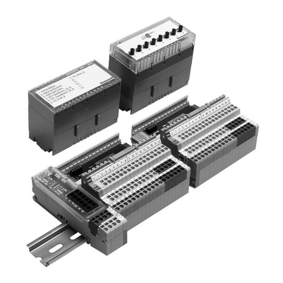
The XFL521B, 522B, 523B, and 524B modules are L
compliant digital and analog I/O modules which can be
installed at strategic locations within a building. These
modules convert sensor readings and provide output signals
used for operating actuators via L
variables (SNVTs). Each Distributed I/O module plugs into a
base terminal block allowing communication with controllers
®
via the built-in Echelon
L
ON
minal block provides spring clamp terminals for easy connec-
tion of field cables from the various sensors and actuators.
The modular system allows Distributed I/O modules to be
removed from the system without disturbing other modules.
The module with terminal block mounts easily onto a DIN rail.
When using CARE, the Distributed I/O modules can be
automatically bound and commissioned to the Excel 500
CPU (XC5010C, XC5210C, XCL5010) and XL50. When the
modules are used by other controllers, provided plug-ins
permit the modules to be commissioned by CARE 4.0 or by
any LNS network management tool.
® U.S. Registered Trademark
Copyright © 2002 Honeywell Inc. • All Rights Reserved
ON
W
standard network
ON
ORKS
W
bus interface. The ter-
ORKS
523B, AND 524B MODULES
FEATURES
• L
M
™ compliant
ON
ARK
• 2-wire L
W
ON
ORKS
and I/O
• No additional field terminals required
• Usable with Excel 500 controllers in conjunction with
standard internal I/O modules
• Automatic binding and commissioning to Excel 500
controllers when using CARE
• Connector module with sliding bus connector
(eliminating the need to wire together neighboring
modules)
• Fast connection due to spring clamp terminals
• Module exchange during operation
• Alarm in case of defective module
• Mechanical coding prevents mismatching of modules
• Power LED (L1, green) and L
(L2, red) on all electronics modules
• Status LEDs for outputs and digital inputs
• Optional manual override modules for analog and
digital output modules with feedback
• XILON for wiring test
DESCRIPTION
M
These Distributed I/O modules use a Neuron® chip and an
ARK
FTT-10A free topology transceiver for communication on a
L
W
bus and comply with L
ON
ORKS
Guidelines V3.2.
Table 1. Modules and accessories
Item
XFL521B
Analog input module
XFL522B
Analog output module
XFL523B
Digital input module
XFL524B
Digital output module
XSL511
L
XSL512
Manual terminal disconnect module
XSL513
Terminal block for XFL521x, 522x, 523x
XSL514
Terminal block for XFL524x
XFR522A
Analog output manual override module
XFR524A
Digital output manual override module
XAL-Code
To prevent mismatching modules
XAL-Term
Interface to the L
209541B
LonWorks bus termination modules
XAL 2
Cover release tool
XAL 1
Swivel label (for manual override modules)
Distributed I/O
XFL521B, 522B,
PRODUCT DATA
®
bus interface between controller
W
ON
ORKS
M
Application Layer
ON
ARK
Description
W
connector module
ON
ORKS
W
bus
ON
ORKS
EN0B-0090GE51 R0802
service LED
74-2145-2
Advertisement

Related Manuals for Honeywell Excel 5000 open XFL521B


Summary of Contents for Honeywell Excel 5000 open XFL521B
- Page 1 XAL-Term Interface to the L ORKS 209541B LonWorks bus termination modules XAL 2 Cover release tool XAL 1 Swivel label (for manual override modules) ® U.S. Registered Trademark Copyright © 2002 Honeywell Inc. • All Rights Reserved EN0B-0090GE51 R0802 74-2145-2...
- Page 2 DISTRIBUTED I/O INTEROPERABILITY the Distributed I/O module to set its location string. If a The Distributed I/O modules are compliant to the L network management node commands this nci to Application Layer Interface Guidelines, version 3.2. The “CFG_EXTERNAL”, then the module will no longer modify its modules contain a L Node Object to allow monitoring Location String.
- Page 3 DISTRIBUTED I/O Table 3. Node Object network variables NV Name Type Range Description RQ_NORMAL Upon receiving an update to nviRequest, nvoStatus is RQ_DISABLE updated. RQ_ENABLE RQ_SELF_TEST is used only in the XFL522B analog nviRequest SNVT_obj_request RQ_UPDATE_STATUS output module for outputs configured as a motor. In RQ_REPOPRT_MASK this case, a synchronization is performed to set the RQ_SELF_TEST...
-
Page 4: Technical Data
DISTRIBUTED I/O TECHNICAL DATA Analog Input Module XFL521B • Eight inputs (AI1 – AI8) 0...10 Vdc (see EN1R-1047 for impedance information) 0...20 mA (via external 500-ohm resistor) 4...20 mA (via external 500-ohm resistor) NTC 20K ohm (-50 °C to +150 °C) PT1000 (-50 °C to +150 °C) •... - Page 5 DISTRIBUTED I/O Table 5. L Object NVs for the XFL521B NV Name Type Range Description The value of the input channel connected to a 0...10 V signal after it has been filtered. Voltage 0x000 (0.00 mV) to nvoAiValue SNVT_volt_f is transmitted in mV. When configured for a 0x461C4000 (10 V) temperature sensor, the channel transmits the measured resistance.
- Page 6 DISTRIBUTED I/O Analog Output Module XFL522B • Eight outputs (AO1 – AO8), short-circuit proof • Signal levels 0...10 Vdc = 11 Vdc, I = +1 mA, -1 mA • Protected outputs up to 40 Vdc / 24 Vac • 8-bit resolution •...
- Page 7 DISTRIBUTED I/O Table 6. L Object NVs for the XFL522B NV Name Type Range Description nviValue SNVT_switch Receives the value for the output channel. Transmits the feedback value of the actuator output. If the manual override switch is set to 0, or if the manual override module is not plugged in, the feedback output reflects the value of nviValue.
- Page 8 Attention: Always connect the same side of the transformer to the same side of XSL511. Connector Module Connector Module XSL 511 XSL 511 shield shield shield shield Honeywell AG Made in Germany Honeywell AG Made in Germany Fig. 6. XFL522B analog output module EN0B-0090GE51 R0802...
- Page 9 DISTRIBUTED I/O Digital Input Module XFL523B • Twelve inputs (DI1 – DI12) • R = 10K ohm • Max. 20 Hz input frequency • ON/OFF state: OFF: U ≤ 2.5 Vdc; ON: U ≥ 5 Vdc • Protected switching up to 40 Vdc / 24 Vac •...
- Page 10 DISTRIBUTED I/O Table 7. Relation between physical state and logical status as defined by the point attribute NO/NC for the XFL523B Contact position NO/NC attribute Logical status Input voltage LED switch on LED switch off ≤ 2.5 V open green closed ≥...
- Page 11 DISTRIBUTED I/O Digital Output Module XFL524B • Six isolated change-over contacts • Max. voltage U = 230 Vac per output • Max. current I = 2 A per output • LED per channel OFF: LED off ON: LED illuminated (yellow) •...
- Page 12 DISTRIBUTED I/O Table 10. L Object NVs for the XFL524B NV Name Type Range Description nviValue SNVT_switch Receives the value for the output channel. Transmits the feedback value of the Actuator Object. If the manual override switch is set to auto, or if the manual override module is not plugged in, the feedback output reflects the value of nviValue.
- Page 13 DISTRIBUTED I/O Terminal Block XSL513 for XFL521B/522B/523B • Mounts on a DIN rail (top-hat rail) • Spring-clamp terminals • Safety latch secures XFL module in its position • Mechanical coding using coding pins; an optional package with 20 coding combs is available (XAL-Code) The XSL513 Terminal Block has three rows of terminals: Top row: 18 signal terminals (gray);...
- Page 14 DISTRIBUTED I/O Manual Override Module XFR522A for XFL522B (Analog Output) • Mounts on top of the XFL522B module • Potentiometer settings automatic or variable 0 – 100% • XFL522B LEDs remain visible • Dimensions (WxLxH): 47x97x20 mm • Feedback signal including point name, status (manual, auto), and point value provided to CPU The XFR522A manual override module mounts directly on The manual override module works even if the CPU...
-
Page 15: Terminal Block Connection
DISTRIBUTED I/O Terminal Block Connection NOTE: The terminal blocks are to be mounted on 1.5-inch Table 12. Max. current ratings for other modules (35-mm) DIN rails (DIN/EN 50 022 35x15). The Maximum current rating at: mounting panel should have a minimum thickness of Module 0.08 inch (2 mm) to provide reference potential for 19.2 Vac... - Page 16 DISTRIBUTED I/O Push the sliding bus connector to the left until it locks onto the matching circuit board section on the adjacent connector module (see Fig. 10). If necessary (e.g. in case of vibrations due to refrigerating equipment, etc.), mount braces (see Fig. 11).
- Page 17 DISTRIBUTED I/O Mounting / Dismounting the Braces and Type-C Safety Latches Fig. 11. Mounting braces (steps 1a and 1b) and mounting (2, 3, and 4) and dismounting type-C safety latches (steps 5 and 6) Mounting Accessories See also section "Accessories, Standards, Ratings, and Literature"...
- Page 18 DISTRIBUTED I/O Coding the Terminal Block The terminal block is coded using the XAL-Code, (package of CAUTION 20 combs). Mixing the modules can destroy them. The terminal block is coded by inserting pins into designated location holes on the terminal block in the base. This codes the electronics modules to their respective terminal blocks.
-
Page 19: Setting The Module Address
DISTRIBUTED I/O Setting the Module Address NOTE: The module address is set using the rotary HEX switch (in the case of applications prior to CARE 4.0). All modules will report the setting of the 16-position rotary HEX switch as a 2-byte ASCII number in the lowest 2 bytes of the Neuron®... - Page 20 DISTRIBUTED I/O The manual override modules are installed as follows: 1. Switch off the power to the output module; or unlock the safety latch and unplug the module from the terminal block as described in section "Removing Modules and Terminal Blocks".
- Page 21 DISTRIBUTED I/O Removing Modules and Terminal Blocks module by pushing a screwdriver into one of the notches of the sliding bus link and sliding it backwards into its The electronics modules and terminal blocks can be removed home position (terminal block) with small sideways move- by carrying out the following steps: ments.
- Page 22 NOTE: The cable types listed above are as recommended Fig. 31. Free topology examples by Echelon® in their FTT-10A User Guide. The cable recommended by Honeywell is the level IV, 22 The FTT specification includes two components that must be AWG, solid core, non-shielded cable. Belden part met for proper system operation.
- Page 23 DISTRIBUTED I/O device device device 200 m device 100 m (656 ft.) termination 100 m (328 ft.) device module (328 ft.) 100 m termination (328 ft.) 200 m module (656 ft.) termination device module 100 m 100 m shield shield 200 m (328 ft.) (328 ft.)
- Page 24 DISTRIBUTED I/O Commissioning Distributed I/O Modules IMPORTANT: Full L functionality requires an Excel 500 The following refers to the commissioning of Distributed I/O controller with controller firmware version 2.04.xx (or modules in conjunction with Excel 500 controllers into which later), a 3120E5 Neuron chip, and Distributed I/O controller firmware version 2.04.xx has been downloaded.
- Page 25 When Distributed I/O modules are used exclusively by Distributed I/O modules are assigned to their host Excel 500 Honeywell Excel 500 controllers, it is possible to auto- controller automatically, and autobinding is performed. matically bind their NVs to the controller. This is referred to as "autobinding."...
- Page 26 DISTRIBUTED I/O MMI. Such modules must be decommissioned using been made during the test mode, the assignments are the L network management tool, or the automatically saved in Flash memory. These assignments ORKS service pin must be pressed for at least can be reused for the application after the application has ORKS three seconds.
- Page 27 L service button. ORKS The hardware is defective if this is not the case. Please contact Honeywell if the above actions do not solve 2. Switch the power ON / OFF. the problem. Service Pin Message and LED...
- Page 28 DISTRIBUTED I/O being downloaded from the installation tool and the IMPORTANT installation tool itself. For additional information on service In Table 19, the words ”configured”, “unconfigured”, LED behavior, see Table 19 and Fig. 38. “application”, and “applicationless” refer only to the communication layer running on the Neuron®...
-
Page 29: Side View
DISTRIBUTED I/O Accessories, Standards, Ratings, and Literature Accessories Approvals and Standards • CE and EN 50082-1 — XAL 1 Swivel Label Holder (required for Manual Override Modules, package includes 10 XAL 1 swivel labels). — XAL 2 Cover Release Tool (required for opening the Environmental Ratings module housing e.g. - Page 30 Fig. 41. Dimensions of XSL511 L connector module in inches (mm) ORKS Control Products Control Products Control Products Honeywell Inc. Honeywell Limited-Honeywell Limitee Honeywell AG Honeywell Plaza 155 Gordon Baker Road Böblinger Straβe 17 Manufacturing P.O. Box 524 North York, Ontario D-71101 Schönaich...
Need help?
Do you have a question about the Excel 5000 open XFL521B and is the answer not in the manual?
Questions and answers