
Related Manuals for Honeywell PW6K1IN


Summary of Contents for Honeywell PW6K1IN
- Page 1 Pro-Watch 6000 Input Module PW6K1IN Installation Guide July 14, 2008 © 2008 Honeywell. All rights reserved. 800-01952, Revision B...
- Page 2 All product and brand names are the service marks, trademarks, registered trademarks, or registered service marks of their respective owners. Printed in the United States of America. Honeywell reserves the right to change any information in this document at any time without prior notice.
-
Page 3: Table Of Contents
ONTENTS Front Matter Warnings and Cautions ..................v Disclaimer ......................vi Unpacking Procedure ..................vii Shipping Instructions ..................vii Limited Warranty ....................viii Confidentiality....................viii Installing the PW-6000 Input Module Description ......................1 Specification......................2 Set Up........................2 LED Operation ...................... 5 Power........................ - Page 4 www.honeywell.com...
-
Page 5: Front Matter
DO NOT ACCEPT VERBAL APPROVALS, BECAUSE THEY ARE NOT VALID. Honeywell never recommends using the PW-6000 or related products for use as a primary warning or monitoring system. Primary warning or monitoring systems should always meet local fire and safety code requirements. The installer must also test the system on a regular basis by instructing the end user in appropriate daily testing procedures. -
Page 6: Disclaimer
Customer harmless for any costs or damages including reasonable attorneys' fees which Customer may be required to pay as a result of the defective Product or the negligence of Honeywell, its agents, or its employees. -
Page 7: Unpacking Procedure
• If any other defect is apparent, call for a return authorization. Shipping Instructions To ship equipment back to Honeywell, Inc.: 1. Contact the customer service department at 800-232-4576 before returning equipment. When you call please have available: •... -
Page 8: Limited Warranty
All Products sold or licensed by Honeywell include a warranty registration card which must be completed and returned to Honeywell by or on behalf of the end user in order for Honeywell to provide warranty service, repair, credit or exchange. All warranty... -
Page 9: Installing The Pw-6000 Input Module
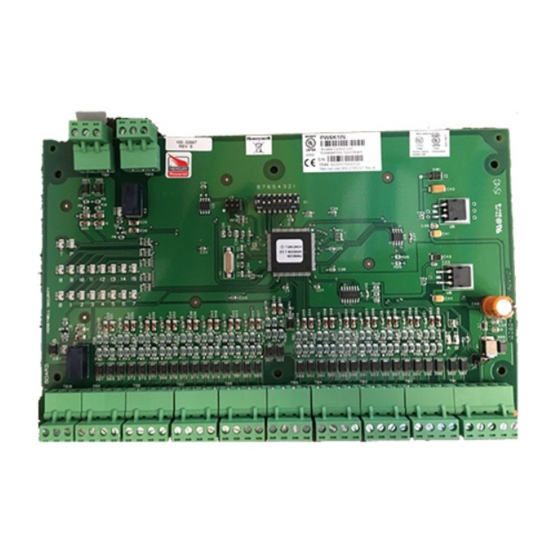
Installing the PW-6000 Input Module Description The PW-6000 Input Module provides connections for 16 supervised inputs and two relay outputs. You can either mount the board in a rack or open and flat. If you rack-mount the board, only one edge is accessible for wiring; however, a flat mount increases the amount of available I/O slightly but significantly decreases the number of boards that can be mounted in one enclosure. -
Page 10: Specification
0°C to +49°C, operating, -55°C to +85°C, storage Humidity 0% to 85% RHNC Set Up Table 1: PW-6000 Input Module Jumper Settings Jumper Setting Default Selected Port 1 RS-485 EOL terminator is not active Port 1 RS-485 EOL terminator is active www.honeywell.com... - Page 11 Installing the PW-6000 Input Module Set Up Table 2: PW-6000 Input Module DIP Switch Settings Selection ADDRESS 0 ADDRESS 1* ADDRESS 2 ADDRESS 3 ADDRESS 4 ADDRESS 5 ADDRESS 6 ADDRESS 7 ADDRESS 8 ADDRESS 9 ADDRESS 10 ADDRESS 11 ADDRESS 12 ADDRESS 13 ADDRESS 14...
- Page 12 Table 2: PW-6000 Input Module DIP Switch Settings (continued) Selection ADDRESS 23 ADDRESS 24 ADDRESS 25 ADDRESS 26 ADDRESS 27 ADDRESS 28 ADDRESS 29 ADDRESS 30 ADDRESS 31 Reserved 9,600 BPS 19,200 BPS 38,400 BPS* Not Used* * = Default www.honeywell.com...
-
Page 13: Led Operation
Installing the PW-6000 Input Module LED Operation LED Operation The Input Board uses two onboard LEDs (D1 and D2) to provide status information during the power-up sequence as well as during normal operation. Table 3: PW-6000 Input Module Onboard LED Settings Mode LED D1 LED D2... - Page 14 Input 6 status Input 7 status Input 8 status Input 9 status Input 10 status Input 11 status Input 12 status Input 13 status Input 14 status Input 15 status Tamper status Power status Relay 0 status Relay 1 status www.honeywell.com...
-
Page 15: Power
Installing the PW-6000 Input Module Power Power The Input Board accepts 12VDC with an operating range of 10 to 16VDC and consumes 250mA of current. Locate power source as close to this board as possible. Connect power with minimum of 18AWG wire. Note: POLARITY for 12VDC power is important. -
Page 16: Wiring
The following circuit is suggested. Locate the protection circuit as close to the load as possible (within 12 inches [30cm]); the effectiveness of the circuit decreases as the distance from the load increases. www.honeywell.com... -
Page 17: Mounting Options
Mounting Options This board can be mounted on-edge in the rack-mount enclosure provided by Honeywell or it can be mounted flat against any surface using standoffs under the mounting holes provided in each of the four corners of this board. -
Page 18: Wiring Diagram For Connectors 1 Through 12
IN13 Common IN14 IN14 Common IN15 IN15 Common RS-485 TR+ CardRack PWR RS-485 TR- J 1 - RS-485 RS-485 GND Com Harness* Termination + 12V (Rack Mount Only) LED Operation on page 5 for descriptions of LEDs D1-D22. Note: www.honeywell.com... -
Page 19: Wiring Diagram For Connectors 10 Through 12
Installing the PW-6000 Input Module Wiring Diagram for Connectors 10 through 12 Wiring Diagram for Connectors 10 through 12 Figure 2: PW-6000 Input Module Wiring: Connectors 10-12 INPUT BOARD Temper Switch (In CLOSED position Relay 0 NO when Cabinet Door is closed) Relay 0 C Tamper... - Page 20 Installing the PW-6000 Input Module Wiring Diagram for Connectors 10 through 12 www.honeywell.com...
- Page 21 Honeywell Integrated Security 135 W. Forest Hill Avenue Specifications subject to change Oak Creek, WI 53154 without notice. United States 800-323-4576 © Honeywell. All rights reserved. 414-766-1798 Fax www.honeywellintegrated.com Document 800-01952, Revision B...
Need help?
Do you have a question about the PW6K1IN and is the answer not in the manual?
Questions and answers