
Related Manuals for Assa Abloy HES KS200-640


Summary of Contents for Assa Abloy HES KS200-640
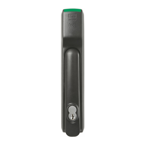
- Page 1 HES, Inc. Phoenix, AZ 1.800.626.7590 www.hesinnovations.com KS200-640 / KS210-640 Server Cabinet Lock Series Installation Instructions 3085006.002 Rev. 3...
-
Page 2: Package Contents
Package Contents Mounting Screws Handling Selectors SFIC Cam DPS Cable Mounting Plate Handle Lock Side Interface Cable Lock Recommended Tools Approved RFID Credential Optional Additional Tools: Normally Open DPS Switches Phillips P2 driver SFIC Core for key override or System Side Interface Cable WT-2 Wiegand Test Box SFIC Blank Plastic Core Specifications... - Page 3 Operating Temperature: -10C to 50C Holding Force: 250 lbs 3085006.002 Rev. 3...
- Page 4 Connector Pin Wiring: Molex 8-Pin Connector Pin Wire Color Description Black Ground (RTN) White Wiegand Data 1 / RS485-A* +VDC (12V-24V) Green Wiegand Data 0 / RS485-B* Blue LED Input (RED) Yellow LED Input (GREEN) Molex 4-Pin Connector Pin Violet Ground (RTN) Pink Tamper/DPS Contact (N.O.) (+)
-
Page 5: Installation
Installation 1. Installing an SFIC Core NOTE 1: A key override (SFIC) provides a backup entry method in the rare case the KS200 or EAC is inactive (Recommended). NOTE 2: The included SFIC cam has been tested with Medeco and Sargent 6- or 7-pin SFIC cores. SFIC SFIC Core... - Page 6 3. Installing the Lock 1. SLIDE lock into cutout. NOTE: (Optional) Install RS485 termination jumper (KS210). (Optional) The DPS signal is closed when the handle is resting in its locked position. The DPS circuit can be extended to include normally open DPS switches arranged in a series to monitor additional doors and panels.
- Page 7 5. ATTACH rear bracket with screws. 6. ENSURE that the lock is fully secured and flush to the mounting surface in order to depress tamper switch on back of device Tamper for correct operation. Switch NOTE: If the tamper switch is not fully depressed, the lock opens the Tamper/DPS+/- contact.
- Page 8 5. Attaching the Wiring New 4-/8-Pin Molex Integrated Wiegand: KS200/KS210 Cabinet Locks, ElectroLynx Wire Color/Function Assignments Connector 8-Pin Molex Connector 4-Pin Molex Connector Pin/Wire Color Black White Green Blue Yellow Violet Pink Gray 12/24 12/24 12 VDC Wiegand 12 VDC Wiegand Tamper/ Tamper/...
- Page 9 * Round trip loss. V = 2 x I x R x xft xft = V / (2 x I x R) Note: Data 0 and Data 1 wires for Wiegand may be reused for OSDP. However, standard Wiegand cable may not meet RS485 twisted pair recommendations for maximum data transmission speed and distance.
- Page 10 Connector and Cable Diagram 3085006.002 Rev. 3...
- Page 11 Server Cabinet Wiring Example 3085006.002 Rev. 3...
- Page 12 6. Testing the Lock with the Access Control System 1. TEST the lock with a known good credential to confirm it will open as desired when installed. a. PRESENT a credential known to the EAC. b. LIFT lever and TURN to open the cabinet. 3085006.002 Rev.
- Page 13 This page intentionally left blank 3085006.002 Rev. 3...
- Page 14 Regulatory This device complies with part 15 of the FCC Rules. Operation is subject to the following two conditions: (1) This device may not cause harmful interference, and (2) this device must accept any interference received, including interference that may cause undesired operation.
Need help?
Do you have a question about the HES KS200-640 and is the answer not in the manual?
Questions and answers