Table of Contents
Advertisement
Quick Links
Advertisement
Chapters
Table of Contents

Subscribe to Our Youtube Channel
Related Manuals for Icom IP501M


Summary of Contents for Icom IP501M
- Page 1 OPERATING GUIDE IP ADVANCED RADIO SYSTEM INTRODUCTION INTRODUCTION IP501M 1. BEFORE USING 1 BEFORE USING 2. BASIC OPERATION 2 BASIC OPERATION 3. ADVANCED OPERATION 3 ADVANCED OPERATION 4. SET MODE 4 SET MODE 5. OPTIONS 5 OPTIONS 6. FOR YOUR INFORMATION...
- Page 2 • Noise Canceling function (TX only) L This document is described based on the IP501M firmware version 1.0.XX. Icom is not responsible for the destruction, damage to, or performance of any Icom or non-Icom equipment, if the malfunction is because of: •...
-
Page 3: Table Of Contents
Section BEFORE USING Supplied accessories ………………………………………………………………………………………………… 1-2 Rear panel connection………………………………………………………………………………………………… 1-3 Mounting the transceiver ……………………………………………………………………………………………… 1-5 Panel Description ……………………………………………………………………………………………………… 1-6 M Front Panel ……………………………………………………………………………………………………… 1-6 DDIAL................................1-6 DIndicators ..............................1-6 DOperating keys ............................1-7 M Function Display ………………………………………………………………………………………………… 1-8... -
Page 4: Supplied Accessories
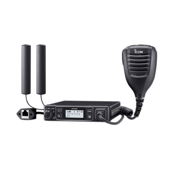
BeFORe uSIng Supplied accessories Speaker microphone Mounting bracket LTe antennas (with cleaning cloth) gPS antenna and DC power cable Microphone hanger double-sided adhesive pad and screw set Cushion and sheet for the Terminals for Spare mounting bracket DC power cable fuses (5A) (R2-6) Self-tapping screws... -
Page 5: Rear Panel Connection
BeFORe uSIng Rear panel connection NOTE: Keep at a distance of 20 cm (8 inches) or more between the LTe antenna of this device and any persons during operation. TIP: After connecting the LTe Antennas and gPS Antenna, wrap the connectors with rubber vulcanizing tape to help in waterproofi... - Page 6 BeFORe uSIng Rear panel connection TIP: After connecting the LTe Antennas and gPS Antenna, wrap the connectors with rubber vulcanizing tape to help in waterproofi ng. Fuse holders R WARNING! NEVER remove the Black fuse holders from the DC power cable.
-
Page 7: Mounting The Transceiver
BeFORe uSIng Mounting the transceiver The universal mounting bracket supplied with your transceiver enables various mounting positions. Mount the transceiver securely with the 4 supplied screws to a thick surface which can support more than 1.5 kg (3.3 lb). nuts Flat washers Mounting bracket... -
Page 8: Panel Description
BeFORe uSIng Panel Description ■ Front Panel Indicators Function display Microphone jack [TX/RX] [MSg] Option key IP501M [PTT] Microphone Speaker [DIAL] Operating keys D DIAL Hold down for 1 second to turn the transceiver On or OFF. • On standby screen: Rotate to adjust the audio volume. -
Page 9: Doperating Keys
BeFORe uSIng Panel Description D Operating keys Assigned key functions may differ, depending on the presetting. [Address] key • Selects a preset address. • Push to toggle the Address Book between the call types. L You can also toggle the address by rotate [DIAL]. All →... -
Page 10: M Function Display
The signal strength is represented by 3 bars. L When the transceiver location is out of the service area, or cannot receive the control signal, the (out-of-area) icon blinks. L If the IP501M has not been authenticated, is displayed. : Call types Shows the call type. - Page 11 BASIC OPERATION Section Basic operation ………………………………………………………………………………………………………… 2-2 M Turning the transceiver ON or OFF …………………………………………………………………………… 2-2 M Receiving and Transmitting …………………………………………………………………………………… 2-2 Using the Address book ……………………………………………………………………………………………… 2-3 DSelecting a call-to party from the Address book ..................2-3 DSelecting a call-to party from the Call history ...................2-3...
-
Page 12: Basic Operation
Basic operation ■ Turning the transceiver ON or OFF Turning ON: Hold down [DiAL] for 1 second to turn ON the transceiver. ip501M • The standby screen is displayed as shown to the right. Ver. x.x.xx/x L It may take a few minutes to boot up the transceiver for the fi rst time. -
Page 13: Using The Address Book
BASiC OpeRATiON Using the Address book You can select a call-to party from the Address book or Call history. D Selecting a call-to party from the Address book The [Address] key can be used, depending on a preset. Ask your dealer for details. About the call type: All call: Transmit to all of the transceivers that belongs to the network. - Page 14 ADVANCED OPERATION Section Sending a message (Message Call) ………………………………………………………………………………… 3-2 M Selecting a call-to party ………………………………………………………………………………………… 3-2 M Sending a message …………………………………………………………………………………………… 3-2 DSending a preset message ........................3-2 DCreating and sending a message using the optional HM-230HB.............3-2 Browsing received messages………………………………………………………………………………………… 3-3 Status Call ………………………………………………………………………………………………………………...
-
Page 15: Sending A Message (Message Call)
ADvAnCED OPErATIOn Sending a message (Message Call) You can send a message, depending on a presetting. Ask your dealer for details. ■ Selecting a call-to party 1. Push [Address] to display the Address book. • The Address book is displayed. 2. -
Page 16: Browsing Received Messages
ADvAnCED OPErATIOn Browsing received messages You can browse received messages, depending on the presetting. Ask your dealer for details. 1. Push [Call History] to display the Call history. • The Call history is displayed. 2. Push [Call History] to display “Rx MSG log.” Rx MSG log L May be required to push [Call History] several times, depending on the presetting. -
Page 17: About The Talkgroup Call
The Talkgroup Call function enables the user to communicate with call-to parties in the same Talkgroup. For example, in the illustration below, when IP501M “00004” in its normal group “10001” selects Talkgroup “20001,” it is excluded from group “10001,” and can communicate with only IP501Ms “00006” and “00008” that belong to the Talkgroup “20001.”... -
Page 18: Dselecting A Talkgroup Number
ADvAnCED OPErATIOn About the Talkgroup Call D Selecting a Talkgroup number You can select a Talkgroup number if the Talkgroup Call function is assigned to the [FUnC] or [Address] key. Ask your dealer for details. Selecting with a [FUNC] key: 1. -
Page 19: Emergency Call Function
• returns to the Standby screen when you release [PTT]. NOTE: The Emergency function may not properly work, depending on the surrounding environment such as obstructions, weather condition, and so on. Icom is not responsible for the destruction or damage caused by using the Emergency Call function. -
Page 20: Other Functions
NOTE: The Lone Worker function may not properly work, depending on the surrounding environment such as obstructions, weather condition, and so on. Icom is not responsible for the destruction or damage caused by using the Lone Worker function. - Page 21 SET MODE Section Using the Set mode …………………………………………………………………………………………………… 4-2 DBasic Set mode ............................4-2 DDetailed Set mode ............................4-2 DUsing the Set mode ..........................4-2 Set mode items ………………………………………………………………………………………………………… 4-3...
- Page 22 Set moDe Using the Set mode You can use the Set mode to set infrequently changed values or function settings. the transceiver has 2 types of Set mode, as shown below. L You cannot transmit or receive while the transceiver is in the Set mode. D Basic Set mode z Hold down [FUNC] for 3 seconds to enter the Set mode.
- Page 23 Set moDe Set mode items the shaded items are also displayed in the Basic Set mode. L Items or default values may be different, depending on the transceiverʼs version or presettings. Ask your dealer for details. Item Description Option/range Default Deletes logs.
- Page 24 Set moDe Set mode items the shaded items are also displayed in the Basic Set mode. L Items or default values may be different, depending on the transceiverʼs version or presettings. Ask your dealer for details. Item Description Option/range Default VoX threshold Sets the VoX threshold level.
- Page 25 Set moDe Set mode items the shaded items are also displayed in the Basic Set mode. L Items or default values may be different, depending on the transceiverʼs version or presettings. Ask your dealer for details. Item Description Option/range Default Bt Auto Connect* Selects whether or not to automatically connect a enable or Disable...
- Page 26 Set moDe Set mode items the shaded items are also displayed in the Basic Set mode. L Items or default values may be different, depending on the transceiverʼs version or presettings. Ask your dealer for details. Item Description Option/range Default Bt one touch Selects whether or not to enable the one-touch Ptt Disable or enable...
- Page 27 Set moDe Set mode items the shaded items are also displayed in the Basic Set mode. L Items or default values may be different, depending on the transceiverʼs version or presettings. Ask your dealer for details. Item Description Option/range Default Show Network Selects whether or not to display the “Network Disable or enable...
- Page 28 OPTIONS Section Options ………………………………………………………………………………………………………………… 5-2 Using the HM-230HB command microphone ……………………………………………………………………… 5-3 M Connecting the HM-230HB …………………………………………………………………………………… 5-3 M Panel description ………………………………………………………………………………………………… 5-3 ® Using the Bluetooth device ………………………………………………………………………………………… 5-4 M About the VS-3 Bluetooth headset …………………………………………………………………………… 5-4 M Pairing with a Bluetooth device ………………………………………………………………………………… 5-5 M Settings for the Bluetooth function ……………………………………………………………………………...
-
Page 29: Options
Cable length: Approximately 2 m (6.5 feet) The Bluetooth headset with a [PTT] switch. • About third-party Bluetooth headsets: Cables Icom has checked the PTT operation with some • OPC-2355 3M Peltor headsets such as the WS Headset XP, extension cable WS ProTac XP and WS Alert XP. -
Page 30: M Connecting The Hm-230Hb
You can use the transceiver more comfortable using the HM-230HB command microphone ■ Connecting the HM-230HB Turn OFF the transceiver, and insert the HM-230HB connector into the microphone jack until it locks. Turn OFF Microphone jack IP501M ■ Panel description [TX/RX] indicator Option key [VOL] control [Emergency] •... - Page 31 OPTIONS Using the optional HM-230HB command microphone ■ Using Option keys The function shown below may be usable by using Option keys, depending on the presetting. Ask your dealer for details. Option key Function Description [Emergency] Message Push an Option key to display the “Message.” You can select a preset message to send.
- Page 32 [PTT] switch. [PTT] • The [FWD], [RWD], and [PLAY] keys on the VS-3 are [VOL] (+) disabled while using the headset with the IP501M. [VOL] (–) Indicator • If the headset does not work correctly, even if the power is [PWR] ON, push [RESET] with a pin to force power OFF.
-
Page 33: Using The Bluetooth ® Device
• If found, the device’s name and BD address are displayed on the screen. (Example: ICOM BT-002) Search BT Device ICOM BT– 0 02 : 00 2. Rotate [DIAL] to select the headset to pair and connect, and then push [Call History]. -
Page 34: M Deleting A Device From The Pairing List
2. Select the device to disconnect, and then push [Call History]. Pairing List • “Unconnected” is displayed if the headset or device is correctly disconnected. ICOM BT–002 : 00 L Do the same steps to reconnect to the Bluetooth device. Unconnected ■... -
Page 35: M Initializing The Pairing Lists
OPTIONS Using the Bluetooth device ® ■ Initializing the Pairing lists If you have problems with Bluetooth operation, initialize the pairing lists, as shown below. Initializing the Pairing list of the transceiver L All the paired Bluetooth devices are deleted from the Pairing list by the initialization. L The Pairing list is not initialized by the RESET function in the Detailed Set mode. - Page 36 FOR YOUR REFERENCE Section Troubleshooting ……………………………………………………………………………………………………… 6-2 Specifications ………………………………………………………………………………………………………… 6-3 D General ………………………………………………………………………………………………………… 6-3 D LAN …………………………………………………………………………………………………………… 6-3 D Audio …………………………………………………………………………………………………………… 6-3 D 3G (W-CDMA) ………………………………………………………………………………………………… 6-3 D LTE …………………………………………………………………………………………………………… 6-3 D GNSS ………………………………………………………………………………………………………… 6-4 D Bluetooth ……………………………………………………………………………………………………… 6-4...
- Page 37 FOR YOUR REFERENCE Troubleshooting The following conditions are not due to a malfunction. Check before sending a request for repair. No power comes ON. • Bad connection to the power supply. - Check the connection to the transceiver and power supply. (p. 1-3) •...
- Page 38 FOR YOUR REFERENCE Specifications L Measurements made without an antenna. L All stated specifications are subject to change without notice or obligation. D General Power supply DC 13.8 V ±10%/DC 26.4 V ±10% Current drain 1.2 A maximum (DC 13.8 V), 0.8 A maximum (DC 26.4 V) Operating Temperature –10°C ~ +60°C, 14°F ~ 140°F...
- Page 39 FOR YOUR REFERENCE Specifications D GNSS 1575.42 MHz ±1.023 MHz GLONASS 1597.5 ~ 1605.8 MHz D Bluetooth Frequency range 2402 ~ 2480 MHz Transmission power Conducted 4.5 dBm Version Bluetooth Version 2.1+EDR Profile HFP, HSP, SPP...
- Page 40 A7536-2EX-0a 1-1-32 Kamiminami, Hirano-ku, Osaka 547-0003, Japan © 2019 Icom Inc. Aug. 2019...
Need help?
Do you have a question about the IP501M and is the answer not in the manual?
Questions and answers