Sign In
Upload
Manuals
Brands
Gotting Manuals
Antenna
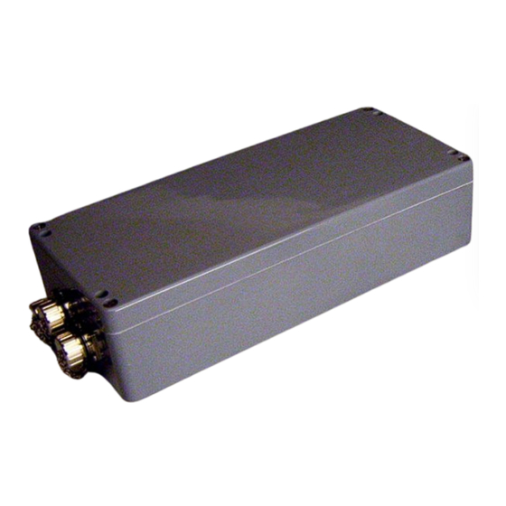
HG 06150ZA
Gotting HG 06150ZA Manuals
Manuals and User Guides for Gotting HG 06150ZA. We have
1
Gotting HG 06150ZA manual available for free PDF download: Manual
Gotting HG 06150ZA Manual (63 pages)
Positioning and Identification Antenna
Brand:
Gotting
| Category:
Antenna
| Size: 1 MB
Table of Contents
Table of Contents
2
1 Introduction
5
1.1 Accessories
5
Figure 1 Components
5
1.2 Function
6
1.3 Positioning Pulse
6
Table 1 Overview of HG G-98780-A Variants
6
2 Mounting
8
2.1 Transponders
8
Dimensions and Specifications
8
Figure 2 Minimum Iron-Free Area Around Puck Transponder HG 70661
8
Mounting Instructions
8
2.2 Antenna HG 98780-A
9
Figure 3 Mounting the Antenna
9
Figure 4 Position of the Mounting Holes
9
Interface HG 06150ZA/XA (Optional)
11
Figure 5 Outline of the Interface Mounting Bar Case
11
Table 2 Interface Connection Plan
11
3 Installation / Commissioning
12
4 Components and Operation
13
4.1 Operation Conditions
13
4.2 Positioning Antenna on the Vehicle / Crane
13
Figure 6 Positioning Antenna HG 98780ZA/WA
13
HG 98780ZA/WA (with CAN-Bus and RS422 / RS232 Interfaces)
13
Connection Plan of the 12-Pin Socket
14
Figure 7 Outline Antenna HG 98780ZA/WA (with Casing Dimensions)
14
Table 3 Variant ZA/WA: Connection Plan of the 12-Pin Antenna Socket
14
Dimensions
15
Figure 8 Outline of Antenna HG 98780YA/XA (Including Housing Dimensions and Picture of the Terminating Resistor / Terminator)
15
HG 98780YA/XA (with Profibus and RS232/RS422)
15
Pin Allocations X1/X2/X3
16
Table 4 Variant XA/YA: Pin Allocation of the 12 Pin Profibus Connectors X1 / X2
16
Table 5 Variant XA/YA: Pin Allocation of the 12 Pin Connector X3 for the Anten- Na Power Supply/Serial
16
Dimensions
17
HG 98780UA (with Profibus, RS422 and Cable Tails)
17
Pin Allocations X1/X2/X3
18
Positioning Pulse
18
Table 6 Variant UA: Pin Allocation of the Profibus Cable Tails X1/X2
18
Table 7 Variant UA: Allocation of the Cable Tail X3 Antenna Power Supply/Rs 422
18
Figure 10 Connection Possibilities Positioning Pulse
19
Figure 11 Formula: Minimum Update Rate
19
Interfaces
19
List of System Data to be Output
19
Serial (RS 422 / RS 232)
19
Switch-On Characteristics
19
Table 8 Data Words in a Telegram of 15 (14) Byte Length
20
Table 9 Possible System Status Messages
21
List of Commands
22
Table 10 List of System Commands
22
CAN Bus
23
CAN Message Object 1 (Transmission Object)
23
Description
23
Positioning Pulse
23
System Monitor
23
Table 11 Structure of the CAN Message Object 1
23
CAN Message Object 2 (a Identifier; Transmission Object)
24
CAN Message Object 3 (D Identifier; Transmission Object)
24
CAN Message Object 4 (Reference Transponder, Trans- Ponder Programming; Reception Object)
24
Table 12 Structure of the CAN Message Object 2
24
Table 13 Structure of the CAN Message Object 3
24
Profibus
25
Profibus Input Bytes
25
Table 14 Structure of the CAN Message Object 4
25
Table 15 Profibus Input Bytes
25
Output Bytes
26
Software Download
26
Table 16 Profibus Output Bytes
26
Table 17 Significance of the Instruction Bit
26
Accessories (Optional)
27
Figure 12 Converter HG 06150XA for Mounting Bar Installation
27
Serial/Parallel Converter HG 06150ZA/XA
27
Table 18 Output Format When Using the Serial/Parallel Interface
27
5 Software
28
5.1 Terminal Program
28
Parameter Presettings
28
Table 19 Terminal Settings Monitor Program
28
5.2 System Monitor
29
How to Start the Monitor Program
29
Procedure Monitor Only
29
Procedures 3964R/Transparent
29
Operating the Monitor Program
30
Figure 13 Main Menu of the Monitor Program
31
Main Menu
31
Table 20 Description of the System Variables (Monitor Program)
31
Figure 14 Menu: (T)Ime & Code
33
T)Ime & Code
33
Figure 15 Menu: (S)Erial Output
34
S)Erial Output
34
Figure 16 Output „(D)Isplay Telegram Content
35
C(A)N Parameters
36
Figure 17 Menu: C(A)N-Parameter
36
Figure 18 Menu: P(R)Ofibus-Parameters
37
P(R)Ofibus-Parameters
37
B)Oot Load
38
Cs(V)
38
Table 21 Possible Profibus Status Messages
38
Software Update (Antenna Software)
39
Installation of the Program for Software Update
39
Software Update
40
Figure 19 Update Program: Operating Elements
41
Figure 20 Update Program: Programing Procedure
42
6 Maintenance
43
7 Troubleshooting
44
Table 22 Troubleshooting
44
8 Technical Data
45
8.1 Antenna
45
Table 23 Technical Data Antenna HG 98780-A
45
Table 24 EMC-Testing
46
Parallel Converter (Optional)
47
Table 25 Technical Data Parallel Converter HG 06150ZA/XA (Optional)
47
9 Appendix
48
Effective Antenna Area
48
Figure 21 Diagram 1, Reception Voltage S Within the Antenna Area at a Reading
48
Figure 22 Diagram 2, Reception Voltage S Within the Antenna Area at Reading
48
Figure 23 Diagram 3, Reception Voltage S Within the Antenna Area at Reading
49
Figure 24 Diagram 4, Reception Voltage S Within the Antenna Area at Reading
49
Figure 25 Diagram 5, Reception Voltage X Within the Antenna Area at Reading
50
Figure 26 Diagram 6, Reception Voltage X Within the Antenna Area at Reading
50
B Positioning Accuracy
51
Figure 27 Diagram 1, Location of the Generation of the Posipulse at Reading DI
51
Figure 28 Diagram 2, Location of the Generation of the Posipulse at Reading DI
51
Figure 29 Diagram 3, Location of the Generation of the Posipulse at Reading DI
51
Figure 30 Diagram 4, Location of the Generation of the Posipulse at Reading DI
52
Figure 31 Diagram 5, Location of the Generation of the Posipulse on the Center
52
Attenuation of the Reception Level Caused by Metal
53
Figure 32 Attenuation of the Reception Level Caused by Metal
53
Table 26 Dependency of the Signal Strength on the Distance between Trans
53
D Influence of Water
54
Figure 33 Attenuation of the Sum Voltage as a Function of the Conductivity of the Water (30 MM Water Level)
54
Figure 34 Attenuation of the Sum Voltage as a Function of the Conductivity of the Water (75 MM Water Level)
54
E Mounting Next to Massive Metal Structures
55
F Procedure 3964R
55
Data Direction Antenna -> PLC
55
Figure 35 Recommended Distances to Massive Metal Structures
55
Data Direction PLC -> Antenna
56
Figure 36 Status Diagram Procedure 3964R; Antenna -> PLC
56
Figure 37 Status Diagram Procedure 3964R; PLC -> Antenna
56
G Procedure „Transparent
57
Data Direction Antenna -> PLC
57
Data Direction PLC -> Antenna
57
HGSD File (Antenna HG 98780XA/YA with Profibus)
57
10 Handbook Conventions
58
List of Figures
59
12 List of Tables
61
13 Index
62
14 Copyright and Terms of Liability
63
14.1 Copyright
63
14.2 Exclusion of Liability
63
14.3 Trade Marks and Company Names
63
Advertisement
Advertisement
Related Products
Gotting HG 06150XA
Gotting HG 98860ZA
Gotting HG G-98780-A
Gotting HG G-98760-C Series
Gotting HG G-19334-A
Gotting HG G-19334
Gotting HG G-98830
Gotting HG G-71915
Gotting HG G-98870
Gotting HG G-98870 YA
Gotting Categories
Antenna
GPS
Accessories
Marine Radio
Controller
More Gotting Manuals
Login
Sign In
OR
Sign in with Facebook
Sign in with Google
Upload manual
Upload from disk
Upload from URL