Advertisement
Quick Links
Advertisement

Related Manuals for CHIEF LWM2X1UP


Summary of Contents for CHIEF LWM2X1UP
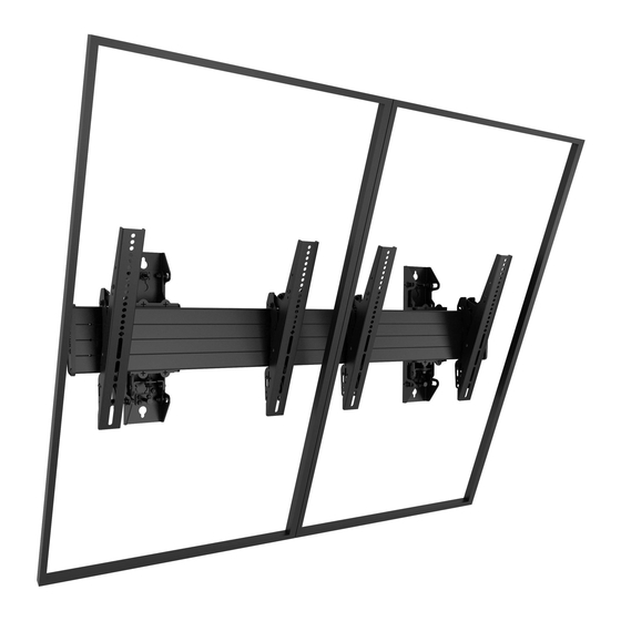
- Page 1 I N S T A L L A T I O N I N S T R U C T I O N S LWM3X1UP LWM2X1UP Portrait Wall-Mounted Menu Boards Spanish Product Description German Product Description Portuguese Product Description Italian Product Description Dutch Product Description French Product Description LWM2X1UP / LWM3X1UP...
-
Page 2: Important Safety Instructions
LWM2X1UP 125 lbs 250 lbs (56.7 kg) (113.4 kg) Chief® is a registered trademark of Milestone AV Technologies. LWM3X1UP 125 lbs 375 lbs All rights reserved. (56.7 kg) (170.1 kg) - Page 3 Installation Instructions LWM2X1UP / LWM3X1UP LEGEND Tighten Fastener Pencil Mark Apretar elemento de fijación Marcar con lápiz Befestigungsteil festziehen Stiftmarkierung Apertar fixador Marcar com lápis Serrare il fissaggio Segno a matita Bevestiging vastdraaien Potloodmerkteken Serrez les fixations Marquage au crayon...
-
Page 4: Tools Required For Installation
3/8" 3/16" 3/16" 1/2" (all included) PARTS [Quantities listed in order for models: LWM2X1UP / LWM3X1UP] DISPLAY ATTACH HARDWARE BAG (2/3) Q (1-46" for LWM2X1UP / 1-68" for LWM3X1UP) (Qty listed per hardware bag) [Horizontal mounting rail] A (8) C (6) - Page 5 Installation Instructions LWM2X1UP / LWM3X1UP WALL ATTACHMENT INFORMATION (LWM3X1UP shown as example) Rail Outside wall uprights (CC) Figure 1 Table 1: Wall Upright Specifications Model (Outside wall upright spacing) (End of rail to wall upright) LWM2X1UP 30" - 40" (762 - 1016mm) "B"...
-
Page 6: Installation
IMPORTANT ! : Refer to Dimensions section at end of between outer bracket and wall upright assembly in four instructions to find specific LWM2X1UP and LWM3X1UP locations. (See Figure 4) dimension requirements BEFORE proceeding with installation. - Page 7 Installation Instructions LWM2X1UP / LWM3X1UP Rotate wall assembly so that height-adjust screw is at top of wall upright assembly. (See Figure 6) Insert one shoulder washer and one steel washer between outer bracket and wall upright assembly in four locations.
- Page 8 LWM2X1UP / LWM3X1UP Installation Instructions Installing to Wood Stud Walls Installing to Concrete Walls Drill one 7/32" (5.5mm) pilot hole in stud at upper mounting Drill one 3/8" x 3-1/2" (9.5mm x 88.9mm) pilot hole at mark slot. (See Figure 8) for upper mounting slot.
- Page 9 Installation Instructions LWM2X1UP / LWM3X1UP Attach Mounting Rail Attach one end cap (S) with two 1/4-20 x 1/2" Phillips head screws (T) to end of mounting rail (Q). (See Figure 10) (CC) (T) x 2 (BB) (back view of rail)
- Page 10 LWM2X1UP / LWM3X1UP Installation Instructions Adjust and Level Mounting Rail Adjust the height of the mounting rail via the wall upright, as necessary, to level the mounting rail on the wall. (See Figure 14) • Turn the wall upright height-adjust screw clockwise (viewed from bottom) to raise the mounting rail.
- Page 11 Installation Instructions LWM2X1UP / LWM3X1UP ATTACH DISPLAYS TO MOUNTING RAIL While supporting both sides of each remaining display, lower display onto mounting rail, hooking top of interface brackets onto front of mounting rail. (See Figure 17) Repeat Steps 3 through 5 for each additional display.
- Page 12 LWM2X1UP / LWM3X1UP Installation Instructions OPTIONAL: Security OPTIONAL: Add padlock (not included) to each interface bracket to lock display to menu board. (See Figure 20) Padlock (Optional) (Displays not shown) (FHB5078 not shown) Figure 20...
- Page 13 Installation Instructions LWM2X1UP / LWM3X1UP DIMENSIONS LWM2X1UP...
- Page 14 LWM2X1UP / LWM3X1UP Installation Instructions DIMENSIONS (continued) SHOWN WITH FHB5078 LWM2X1UP 800 mm ADAPTER INCLUDED WITH LWM2X1UP 0.49 2.21 12.5 56.0 0.49 2.10 12.5 53.4 0.34 33.42 16.75 848.9 425.5 0.34 MINIMUM DEPTH MAXIMUM DEPTH 9.47 240.6 DIMENSIONS: INCHES [MILLIMETERS]...
- Page 15 Installation Instructions LWM2X1UP / LWM3X1UP DIMENSIONS (continued) LWM3X1UP...
- Page 16 LWM2X1UP / LWM3X1UP Installation Instructions DIMENSIONS (continued) LWM3X1UP 15.75 400.0 SHOWN WITH FHB5078 800 mm ADAPTER INCLUDED WITH LWM3X1UP MINIMUM MAXIMUM DEPTH DEPTH 9.47 240.6 DIMENSIONS: INCHES [MILLIMETERS]...
- Page 17 Installation Instructions LWM2X1UP / LWM3X1UP...
- Page 18 LWM2X1UP / LWM3X1UP Installation Instructions...
- Page 19 Installation Instructions LWM2X1UP / LWM3X1UP...
- Page 20 Europe A Franklinstraat 14, 6003 DK Weert, Netherlands P +31 (0) 495 580 852 F +31 (0) 495 580 845 Chief, a products division of Asia Pacific A Office No. 918 on 9/F, Shatin Galleria Milestone AV Technologies 18-24 Shan Mei Street...
Need help?
Do you have a question about the LWM2X1UP and is the answer not in the manual?
Questions and answers