Table of Contents
Advertisement
Quick Links
I N S T A L L A T I O N I N S T R U C T I O N S
Instrucciones de instalación
Installationsanleitung
Instruções de Instalação
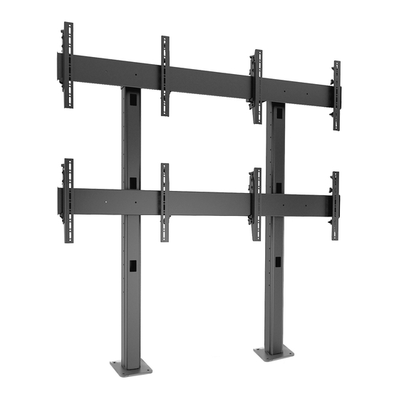
LBM2X2U
LBM3X3U
Istruzioni di installazione
Installatie-instructies
Instructions d´installation
LBM1X2U
LBM3X2U
LBM1X3U
LBM1X2UP
LBM2X2UP
Bolt Down Video Wall
Spanish Product Description
German Product Description
Portuguese Product Description
Italian Product Description
Dutch Product Description
French Product Description
LBM Series
LBM3X1UP
LBM3X2UP
Advertisement
Table of Contents

Related Manuals for CHIEF LBM Series


Summary of Contents for CHIEF LBM Series
- Page 1 Installationsanleitung Installatie-instructies Instruções de Instalação Instructions d´installation LBM2X2U LBM1X2U LBM3X1UP LBM1X2UP LBM3X2U LBM3X3U LBM1X3U LBM3X2UP LBM2X2UP Bolt Down Video Wall Spanish Product Description German Product Description Portuguese Product Description Italian Product Description Dutch Product Description French Product Description LBM Series...
-
Page 2: Important Safety Instructions
LBM3X3U 125 lbs 1125 lbs the information contained in this document. (56.7 kg) (510.3 kg) Chief® is a registered trademark of Milestone AV Technologies. All rights reserved. LBM1X2U 125 lbs 250 lbs (56.7 kg) (113.4 kg) - Page 3 Installation Instructions LBM Series NOTE: The UL Listed LBM Series video walls may be used with the following Listed video wall extension WARNING: Do NOT install LBM Series mounts to any accessories: surface other than concrete! Concrete flooring must be at least 4"...
-
Page 4: Installation Instructions
LBM Series Installation Instructions LBM3X2U MAX WEIGHT: 125 LBS PER DISPLAY 750 LBS TOTAL 108.89 15.75 2765.8 400.0 5.38 3.73 MAX MOUNTING 136.5 94.7 PATTERN HEIGHT 88.27 66.62 64.38 1.50 2242.1 2.53 1692.0 1635.1 38.1 64.1 65.88 SCREEN CENTER 1673.2 MAX HEIGHT 16.38... - Page 5 Installation Instructions LBM Series LBM1X2U 36.00 914.4 15.75 400.0 MAX MOUNTING PATTERN HEIGHT 21.23 539.2 MAX WEIGHT: LBM1X3U 36.00 125 LBS PER DISPLAY 914.4 375 LBS TOTAL CAPACITY 28.77 730.8 400.0 MAX MOUNTING PATTERN HEIGHT 82.39 2092.7 SCREEN CENTER MAX HEIGHT 16.38...
- Page 6 LBM Series Installation Instructions 36.00 LBM1X2UP 914.4 21.23 539.2 31.50 800.0 MAX MOUNTING PATTERN HEIGHT LBM3X1UP MAX WEIGHT: 125 LBS PER DISPLAY 64.38 1635.1 SCREEN CENTER MAX HEIGHT 17.38...
- Page 7 Installation Instructions LBM Series MAX WEIGHT: LBM2X2UP 100 LBS PER DISPLAY 82.38 SCREEN CENTER MAX HEIGHT 17.38 LBM3X2UP MAX WEIGHT: 100 LBS PER DISPLAY 82.38 2092.3 SCREEN CENTER MAX HEIGHT 17.38...
- Page 8 LBM Series Installation Instructions Bolt Down Dimensions BOTTOM VIEW LBM2X2U/LBM3X1UP FOR BOLT DOWN INSTALLATION LBM2X2UP/LBM3X2UP LARGER RADIUS FACES FRONT TO ATTACH TO COLUMN. 8.00 COLUMN BOLT PATTERN NOT SQUARE 203.2 6.00 8.00 152.4 203.2 0.500 12.7 1.00 28.00 25.4 711.2 1.00...
- Page 9 Installation Instructions LBM Series LEGEND Tighten Fastener Pencil Mark Apretar elemento de fijación Marcar con lápiz Befestigungsteil festziehen Stiftmarkierung Apertar fixador Marcar com lápis Serrare il fissaggio Segno a matita Bevestiging vastdraaien Potloodmerkteken Serrez les fixations Marquage au crayon Loosen Fastener Drill Hole Aflojar elemento de fijación...
-
Page 10: Tools Required For Installation
LBM Series Installation Instructions TOOLS REQUIRED FOR INSTALLATION 1/2” (12.7mm) 3/16” (included with all) 3/8” (9.5mm) 1/8” (included with 3X2U,3X3U, 1X2U, 1X3U, 1X2UP) 5/32” (included with 3X3U, 1X3U 1X2U, 1X2UP, 2X2UP, 3X2UP) 3/8” (9.5mm) PARTS -Non-portrait Models- LBM2X2U/LBM3X2U/LBM3X3U/LBM1X2U/LBM1X3U (Portrait next page) - Page 11 Installation Instructions LBM Series Parts - Portrait Models - LBM1X2UP/LBM3X1UP/LBM2X2UP/LBM3X2UP Hardware bag (letters correspond to letters on bag) D (8/12/16/24) A (8/12/16/24) B (8/12/16/24) E (8/12/16/24) C (8/12/16/24) 1/4” *Quantities are listed as M6x12mm M6x16mm .750x.344x.5 M6x30mm (LBM1X2UP/LBM3X1UP/ LBM2X2UP/LBM3X2UP) F (8/12/16/24)
- Page 12 (See Figure 2) WARNING: Do NOT install LBM Series mounts to any surface other than concrete! Concrete flooring must be at least 4" in thickness and NOT be covered with any other type of flooring material.
- Page 13 Installation Instructions LBM Series Column Add-On Installation (LBM3X3U/ Use 5/16-18 x 4 1/2” button head cap screw (AA), two 5/16” washers (CC) and 5/16-18” lock nut (FF) to secure each LBM1X3U/LBM2X2UP/LBM3X2UP only) clamp bracket (P) to column. (See Figure 5)
- Page 14 LBM Series Installation Instructions Use four 5/16-18 x 3/4" button head flange screws (BB) to Hang rails (K or L) into screws installed in previous step to secure each attached clamp bracket (P) to each quick quick connect bases (Q). (See Figure 9) connect base (Q).
-
Page 15: Display Installation
Installation Instructions LBM Series Display Installation Select screw length: (See Figure 12) and (See Figure 13) • Using your hand, insert SHORTEST length screw Place display face down on a soft, non-abrasive surface. of selected diameter (A or F) through 1/4" washer... - Page 16 LBM Series Installation Instructions (portrait models) (A-C or F-H) x 4 (D) x 4 (E) x 4, if necessary Figure 13 WARNING: Exceeding the weight capacity can result in serious personal injury or damage to equipment! It is the LBM2X2U LBM3X2U installer’s responsibility to make sure the combined weight of...
-
Page 17: Cable Management
Installation Instructions LBM Series Starting from the bottom and working up, hang interface Adjustments brackets (Y and Z) to display rails (K or L). (See Figure 14) Height Adjustment Use 1/4-20 x 1 1/4” socket head cap screws (I) to secure interface brackets (Y and Z) to rails for each display. - Page 18 LBM Series Installation Instructions Additional Cable Management Options Cables may be routed through tops of columns and out through the back cable management hole. (See Figure 18) (KK) Figure 20 Figure 18 If rails needed to be installed on top of cable management holes, cables may be routed through quick connect bases (Q) prior to the rails being installed.
- Page 19 Installation Instructions LBM Series...
- Page 20 Europe A Franklinstraat 14, 6003 DK Weert, Netherlands P +31 (0) 495 580 852 F +31 (0) 495 580 845 Chief, a products division of Asia Pacific A Office No. 918 on 9/F, Shatin Galleria Milestone AV Technologies 18-24 Shan Mei Street...
Need help?
Do you have a question about the LBM Series and is the answer not in the manual?
Questions and answers