Advertisement
Quick Links
I N S T A L L A T I O N I N S T R U C T I O N S
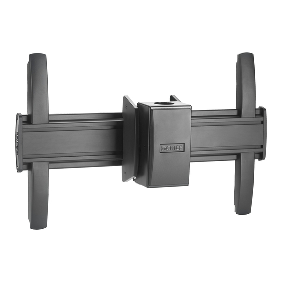
LCM1U
MCM1U
(Shown installed to
(Shown installed to
1-1/2" NPT column as example only)
CPA Series extension column
as example only)
Single Flat Panel Ceiling Mounts
Spanish Product Description
German Product Description
Portuguese Product Description
Italian Product Description
Dutch Product Description
French Product Description
MCM1U / LCM1U / MCM1US / LCM1US
Advertisement


Need help?
Do you have a question about the MCM1U and is the answer not in the manual?
Questions and answers