Table of Contents
Advertisement
Quick Links
I N S T A L L A T I O N I N S T R U C T I O N S
Instrucciones de instalación
Installationsanleitung
Instruções de Instalação
Istruzioni di installazione
Installatie-instructies
Instructions d´installation
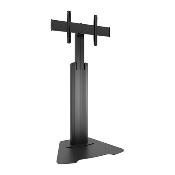
Height Adjustable Video Stand
Spanish Product Description
German Product Description
Portuguese Product Description
Italian Product Description
Dutch Product Description
French Product Description
LFAU
Advertisement
Table of Contents

Related Manuals for CHIEF LFAUB


Summary of Contents for CHIEF LFAUB
- Page 1 I N S T A L L A T I O N I N S T R U C T I O N S Instrucciones de instalación Istruzioni di installazione Installationsanleitung Installatie-instructies Instruções de Instalação Instructions d´installation Height Adjustable Video Stand Spanish Product Description German Product Description Portuguese Product Description...
-
Page 2: Important Safety Instructions
AN ACCESSORY is the secondary Chief Placing a remote control or toy on the stand may encourage product which is attached to a primary Chief product, and may have a component attached or setting on it. a child to climb onto the stand causing the stand to tip over onto the child. -
Page 3: Installation Instructions
Installation Instructions LFAU DIMENSIONS +/-2 ROLL TILT ADJUSTMENT ADJUSTMENT 7.87 [200] MIN 31.50 [800] MAX 15.75 400.0... - Page 4 LFAU Installation Instructions LEGEND Tighten Fastener Pencil Mark Apretar elemento de fijación Marcar con lápiz Befestigungsteil festziehen Stiftmarkierung Apertar fixador Marcar com lápis Serrare il fissaggio Segno a matita Bevestiging vastdraaien Potloodmerkteken Serrez les fixations Marquage au crayon Loosen Fastener Drill Hole Aflojar elemento de fijación Perforar...
-
Page 5: Tools Required For Installation
Installation Instructions LFAU TOOLS REQUIRED FOR INSTALLATION 3/16” (included) PARTS M (1) [Hardware bag] C (1) [column upper A (4) cover] [upright cover] MA (4) MB (4) MC (4) B (2) M4x12mm M4x20mm [interface upright] M4x25mm D (1) [column inner cover] MF (4) MD (4) -
Page 6: Assembly And Installation
LFAU Installation Instructions Assembly And Installation Use remaining 5/16-18 x 3/4” button head cap screw (K) to secure column upper cover (C) to interface head assembly (E). (See Figure 3) Snap column inner cover (D) onto column assembly (F). CAUTION: Attachment holes may be damaged if a power (See Figure 3) drill is used to insert button head cap screws. -
Page 7: Display Installation
Installation Instructions LFAU Display Installation nesting spacer MM), into display mounting hole. Do NOT thread screw into hole at this time. NOTE: Universal washers (MN) are not needed if using M8 WARNING: Exceeding the weight capacity can result in button head cap screws (MJ, MK or ML). serious personal injury or damage to equipment! It is the •... - Page 8 LFAU Installation Instructions Move latches on interface uprights to the “closed” position to secure display to head assembly. (See Figure 8) WARNING: Display may be very heavy! Ensure display may be safely lifted and maneuvered as required to install on stand.
-
Page 9: Cable Management
Installation Instructions LFAU Cable Management Route cables from display through front channel of column assembly. (See Figure 12) NOTE: The following cable management options may vary based on type of display being mounted and user preference. Place FCA clip (N) into groove on back of Fusion mount with cable (example) clip handle in a vertical position. - Page 10 LFAU Installation Instructions Adjustments Pitch Adjustment Turn pitch adjustment knob clockwise to tilt display forward. Height Adjustment (See Figure 16) Remove cable cover (G) to expose height adjustment knob. Turn pitch adjustment knob counterclockwise to tilt display back. (See Figure 16) Turn height adjustment knob clockwise to raise display.
- Page 11 Installation Instructions LFAU Stand Use and Maintenance open position WARNING: Exceeding the weight capacity can result in serious personal injury or damage to equipment! It is the installer’s responsibility to make sure the combined weight of all components located between the LFAU up to (and including) the display does not exceed 200 lbs (90.7 kg).
- Page 12 Europe A Franklinstraat 14, 6003 DK Weert, Netherlands P +31 (0) 495 580 852 F +31 (0) 495 580 845 Chief, a products division of Asia Pacific A Office No. 918 on 9/F, Shatin Galleria Milestone AV Technologies 18-24 Shan Mei Street...
Need help?
Do you have a question about the LFAUB and is the answer not in the manual?
Questions and answers