Advertisement
Quick Links
Advertisement

Related Manuals for Nucraft Kai


Summary of Contents for Nucraft Kai
- Page 1 Kai Installation Instructions...
-
Page 2: Before Beginning Installation
Before Beginning Installation • Read through the entire instruction thoroughly • A minimum of 2 persons is required for this assembly • These instructions reflect typical assemblies. They may not match your specific configuration. • NOTE: Tables 96” and smaller will have the base shipped assembled. -
Page 3: Required Tools
Required Tools • Drill Driver • #2 and #3 Phillips Bit • ¼” – 1/8” – 1/16” Allen Wrench • 5/32” Drill Bit • Laser Level... - Page 4 Provided Hardware Hardware 1 Hardware 4 Hardware 5 Hardware 2 Hardware 3 Hardware 6...
- Page 5 Kai Table with Metal Legs...
- Page 6 Kai Table with Panel Base...
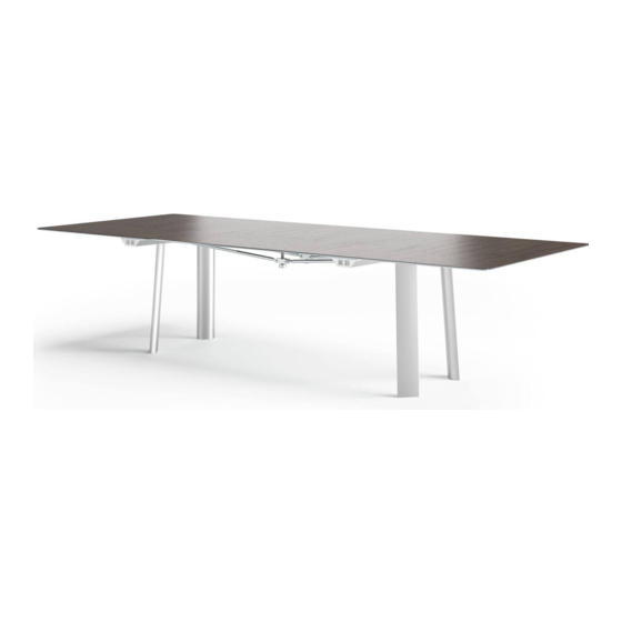
- Page 7 Kai Table...
- Page 8 Step 1A: Attach Legs • Metal Legs – Align and secure the top of the leg plate to the 4 adjacent holes on the frame. • Panel Base – Attach with the 6 fasteners to the adjacent holes on frame. •...
- Page 9 Step 1B: Attach Leg – Boat Table • Metal Legs – Secure the top of the leg to the frame location, using the bracket with two additional holes. – NOTE: Two additional fasteners are provided for this. • Panel Base - Attach with the six fasteners in designated location. –...
- Page 10 Step 2A: insert Attachment Keys • At all frame seems, slide attachment key into each end of each base. • Push the two pieces of frame beams together, and secure using counter-sink screws (hardware 1) into the 4 holes.
- Page 11 Step 2A: Insert Attachment Keys – Boat Style • At all frame seems, slide attachment key into each end of the beam. • Push the two pieces of frame beam together, and secure using counter-sink screws (hardware 1) into the 6 holes.
- Page 12 Step 3: Attach End Pieces • Slide the end piece onto the attachment key. Flush the end of the base. – NOTE: End piece and end frame piece are labeled with numbers. • Use two flat head counter-sink screws (hardware 1) on each side of the end piece to secure. •...
- Page 13 Step 4: Attach Center Column (if applicable) • Center column arrives assembled, but not attached to table. • Attach the angled plate to the table frame using hardware 3.
- Page 14 Step 5: Attach hardware to End of Base • Remove the nut on the outside of the flanges. • Pull the horizontal bolt to slightly move it out. Then insert the eye-bolt. • Place second shoulder nut (spacer) onto the horizontal bolt to secure the eye-bolt. •...
- Page 15 Step 6: Adjust Camber Rods • Each rod has one end that is reverse threaded. As the rod is rotated, it will pull the jack screw toward the top. • Rotate the rods to tighten the jack bolt to the top. •...
- Page 16 Step 7: Attaching Aprons • Align holes of the apron with the holes on the top surface of the base. • Insert flat-head counter-sink screws (hardware 2) through the apron and base frame, from the underside of the apron. Secure with nuts. •...
- Page 17 Step 9: Top • Place the top onto the base. • Before completely tightening the hardware, use a level to check the table is level. Make adjustments to the glides on the bottom of the legs. • NOTE: Glass tops are attached the same. They will sit on bumpers.
- Page 18 Step 10: Secure Top to Base • Insert screws into pucks (hardware 6) at each corner support to secure the top. – Larger tables will have multiple sets of pucks. • Insert screw into the center of the horizontal bar. •...
- Page 19 Step 11: Glass Arm Supports • For glass tops only, there is an extra set of support arms. • These are to be placed a the seams of the glass by hooking around the apron and twisting the knob screws into the rail on the back of the apron.
- Page 20 Step 11: Inserting Power Matrix Bezels • If applicable: – Power Matrixes are installed onto base. – Tops will have a bezel with each power cove. – The bezels are dropped into place.
- Page 21 Step 12: Installing Power Rail • If applicable: • Secure the front edge of the power rail onto the Kai base. • Then secure the power rail by tightening the bolt in the back. – The bolt will be inserted into the extrusion, which allows it to be installed anywhere on the...
- Page 22 Step 13: Installing Power Connections • If applicable: – Wire management will wrap around each end of the base as shown.
Need help?
Do you have a question about the Kai and is the answer not in the manual?
Questions and answers