Advertisement
Quick Links
Advertisement

Related Manuals for Nucraft Kai


Summary of Contents for Nucraft Kai
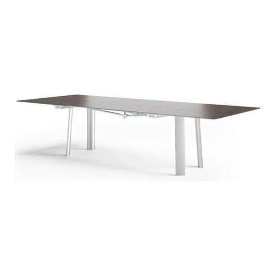
- Page 1 Kai Installation Instructions...
-
Page 2: Before Beginning Installation
Before Beginning Installation Read through the entire instruction thoroughly A minimum of 2 people are required for this assembly These instructions reflect typical assemblies; They may not match your specific configuration Nucraft - Kai 2015... -
Page 3: Required Tools And Hardware
Required Tools and Hardware Drill Driver #2 and #3 Phillips Bit ¼”-1/8”-1/16” Allen Wrench 5/32” Drill Bit Laser Level Nucraft - Kai 2015... - Page 4 Required Tools and Hardware Note: Not all necessary hardware is pictured on this page Nucraft - Kai 2015...
- Page 5 Standard Kai Table Setup Note: For tables 96” and under, base will be assembled shipped. Please skip to Step 9 *For “Boat-shaped” tables, legs are attached to end pieces instead of the center frame. Nucraft - Kai 2015...
- Page 6 Kai Table with Panel Base Nucraft - Kai 2015...
- Page 7 Kai Table with Boat Style Note: Metal leg option is shown Nucraft - Kai 2015...
- Page 8 Note: Leg Attachment using provided fasteners If standard leg attachment, secure the top of the leg in the designated location If panel leg attachment, attach as shown, with the 6 locations fastened Note: Panel leg attachment using provided fasteners Nucraft - Kai 2015...
- Page 9 Step 1a (Boat Style) Attach Legs Panel-leg Boat-style will be attached like rectangular Kai Metal leg Boat-style will be attached using the additional Note: Panel leg attachment using holes provided fasteners Note: Additional fasteners are needed for the metal...
- Page 10 Step 2 Insert Attachment Keys Slide attachment key into each end of each base (4 total) Once inserted, align the two holes and place a flat-head counter-sink screw (hardware #1) to maintain alignment Nucraft - Kai 2015...
- Page 11 (4 total) The entire piece should be inserted into the end extrusion Line up the end extrusion to the center base, and using a screw driver slide the attachment key into the center base structure Nucraft - Kai 2015...
- Page 12 Insert two flat-head counter-sink screws (hardware #1) on each side of each new end piece and secure. Secure the front edge of the end piece by inserting 4 bolts and nuts (hardware #3) Nucraft - Kai 2015...
- Page 13 Step 4 Attach Center Column (if applicable) Center column should arrive assembled. Attach the top angled plate to the frame of the base using hardware #3 (see below – 4 attachment points) Nucraft - Kai 2015...
- Page 14 Place second shoulder nut (spacer) onto horizontal bolt to secure the eye-bolt Secure connection by tightening the washer and nut on outside of flange 1. Eye bolt 2. Nut 3. Nut 4. Washer 5. Spacer Nucraft - Kai 2015 6. Horizontal Bolt/Washer...
- Page 15 Rotate rods to tighten jack bolt to the top Once tightened, thread bolt should be tight against the bottom of the top. Nucraft - Kai 2015...
- Page 16 Step 7 Attaching Side Aprons Align the holes of the apron with the holes on the top surface of the base Insert flat-head counter-sink screws (hardware #2) through the apron and the side length of the steel base from the underside.
- Page 17 End extrusion should slide into pins of the side extrusion Insert flat-head counter-sink screws (hardware #2) through the apron and the steel base from the underside Repeat at other end Nucraft - Kai 2015...
- Page 18 Adjust glides underneath legs if needed Next, place the top on the base without tightening, and continue adjusting if needed Note: Glass top will follow same instructions and will sit on bumpers (Picture shows veneer top) Nucraft - Kai 2015...
- Page 19 A screw should be also be inserted in the horizontal bar (see picture) Insert cautiously, as too much rotation could affect Note: The top shown in the photo the top surface only has 2 pucks per end Nucraft - Kai 2015...
- Page 20 Power coves will be installed onto base. Veneer tops do not have a bezel Glass tops will have a bezel with each power cove (shown at right) The bezels are installed by the “drop-in” method Nucraft - Kai 2015...
- Page 21 Then secure power rail be tightening the bolt in the back of the power rail The bolt will be inserted into the extrusion, therefore it can be installed anywhere along the edge of the table. Nucraft - Kai 2015...
- Page 22 Step 13 Installing Power Connections (if applicable) Wire management will wrap around each end of the base as shown at below Nucraft - Kai 2015...
Need help?
Do you have a question about the Kai and is the answer not in the manual?
Questions and answers