Advertisement
Quick Links
Advertisement

Related Manuals for Nucraft Tesano Conference


Summary of Contents for Nucraft Tesano Conference
- Page 1 Tesano Conference Installation Instructions...
-
Page 2: Before Beginning Installation
Before Beginning Installation • Read through the entire instruction thoroughly • A minimum of 2 people are required for this assembly. For 96” tables and larger it is recommended to have 3 or 4 people available for the install. • These instructions reflect typical assemblies; They may not match your specific configuration ... - Page 3 Required Tools & Hardware Drill Driver #2- Phillips Bit Laser Level ¼” Allen Wrench Tesano...
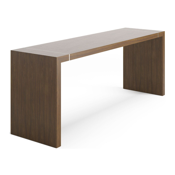
- Page 4 Tesano Conference Tesano...
- Page 5 Tesano Exploded 1. Work Surface 2. Top Beams 3. Mending Plate 4. Base 5. Rail Key 6. Wire Management 7. Power Rail Tesano...
- Page 6 Step 1 Connecting Rails to Bases Run glides out of bases before beginning assembly Loosen bolts (#6) in the keys attached to the beam Insert the beams with rail keys attached, into each of the bases with the “THIS SIDE UP”...
- Page 7 Step 2 Installing Top Insert pins (hardware #4) into the holes along the top edge of base end. Place top onto beams, sliding one end into the pins (hardware #4) of one base Repeat with the base on the opposite end ...
- Page 8 Step 3 Securing Top with Mending Plates Note: -Ensure to center sides of top to the bases prior to attaching mending plates -Square the base up to the top before securing the mending plates Attach mending plate along the center of the metal spacer. Pilot holes should be present.
- Page 9 Step 4a Securing Top Rails With the mending plates secured in place, secure the top beams to the wood rails using hardware #5 long silver screws. The pilot holes in the beam should be facing the ground. Using the cap screws (hardware #6) shown at right, insert into side of rail keys Tesano...
- Page 10 Step 4b Securing Top Rails Center the top beam between the base and tighten cap screws ensuring bottom of beams are flush with one another Secure the top beams to the wood rails using hardware #5 long silver screws. The screws will go through the slotted openings along the face of the beam...
- Page 11 Step 5 Fastening Aprons Locate notch, place in apron toward end of table Place the aprons between the inside of the side rail and the black beam, and fasten them using supplied silver screws (hardware #2). Screws will go through the aluminum extrusion.
- Page 12 Step 6 Installing Wire Management Step (1): Attach jumpers to receptacles Step (2): Run the jumpers around the table, in a u-shape design. Step (3): At one end of the table, the plug in-feed or hardwire should run Jumper through the leg Plug-in Infeed Jumper Tesano...
- Page 13 Step 7 Installing Wire Management Covers Locate the wire management channels. Ensuring that the power duplex lines up with the cutout, fasten the wire management channel using silver screws (hardware #1) and black screws (hardware #3). The label will be facing the top ...
- Page 14 Step 8 Installing Power Rail Unit The power rail unit will come with two black brackets which should be inserted first into the rail. The silver bolts should be inserted into the bracket before inserting into rail. Place power unit over screws ...
Need help?
Do you have a question about the Tesano Conference and is the answer not in the manual?
Questions and answers