Table of Contents
Advertisement
Advertisement
Table of Contents

Related Manuals for ABB NPBA-12


Summary of Contents for ABB NPBA-12
- Page 1 ABB Drives Installation and Start-up Guide PROFIBUS Adapter Module NPBA-12...
- Page 3 PROFIBUS Adapter Module NPBA-12 Installation and Start-up Guide 3BFE 64341588 R0125 REV A EFFECTIVE: 01.01.2001 SUPERSEDES: 11.08.2000 © 2001 ABB Industry Oy. All Rights Reserved.
-
Page 5: Safety Instructions
Safety Instructions Overview This chapter states the safety instructions that must be followed when installing and operating the NPBA-12 PROFIBUS Adapter Module. The material in this chapter must be studied before attempting any work on, or with, the unit. Warnings and Notes This manual distinguishes two sorts of safety instructions. -
Page 6: General Safety Instructions
These functions should not be selected if other equipment is not compatible with this kind of operation, or dangerous situations can be caused by such action. More Warnings and Notes are printed at appropriate instances along the text. NPBA-12 Installation and Start-up Guide... -
Page 7: Table Of Contents
The NPBA-12 PROFIBUS Adapter Module ........ - Page 8 NPBA-12 ........
-
Page 9: Chapter 1 - Introduction To This Guide
Intended Audience The Guide is intended for the people who are responsible for installing, commissioning and using a PROFIBUS Adapter Module with an ABB drive. The reader is expected to have a basic knowledge of electrical fundamentals, electrical wiring practices, the drive, the use of the drive control panel, and the PROFIBUS protocol family. -
Page 10: Conventions Used In This Guide
Data sets are clusters of data sent through the DDCS link between the Data Words NPBA-12 Adapter Module and the drive. Each data set consists of three 16-bit words, ie. data words. The Control Word (sometimes called the Command Word) and the Status Word, References and Actual Values (see Chapter 6) are types of data words;... -
Page 11: Chapter 2 - Overview
Chapter 2 – Overview Overview This chapter contains a short description of the PROFIBUS standard and the NPBA-12 Adapter Module, a delivery checklist, and warranty information. PROFIBUS PROFIBUS is an open serial communication standard that enables data exchange between all kinds of automation components. There are... -
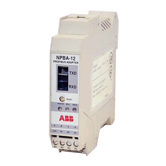
Page 12: The Npba-12 Profibus Adapter Module
(For descriptions see Chapter 7) ABB Drive +24V Screw terminal blocks for the bus cable connection and for power supply connection (see Chapter 4) Figure 2-1 The construction of the PROFIBUS link and the NPBA-12 Adapter Module. NPBA-12 Installation and Start-up Guide... -
Page 13: Compatibility
Chapter 2 – Overview Compatibility The NPBA-12 is compatible with (see also Chapter 5, Parameter no. 8 COMM PROFILE): • ACS 400 • ACS 600 SingleDrive • ACS 600 MultiDrive • ACS 600 MotionControl (ACP 600) • ACS 600 CraneDrive (ACC 600) •... - Page 14 Chapter 2 – Overview NPBA-12 Installation and Start-up Guide...
-
Page 15: Chapter 3 - Mechanical Installation
2. Fasten the rail and ensure the proper earthing as described above. 3. Push the module onto the rail. The module can be released by pulling the locking spring with a screwdriver (see below). 10 mm Earthing 10 mm NPBA-12 Installation and Start-up Guide... -
Page 16: Mounting Inside The Drive
Observe the free space requirements for the module (see the figure above). 7. Push the module onto the rail. The module can be released by pulling the locking spring with a screwdriver (see the figure above). NPBA-12 Installation and Start-up Guide... -
Page 17: Chapter 4 - Electrical Installation
The minimum short term bend radius is 25 mm. Earthing the Module The NPBA-12 module earth is connected to the rail onto which the module is mounted. If the rail is fastened to an earthed metallic assembly plate, the module is automatically earthed, and no external earthing wire is needed. -
Page 18: Dip Switch Settings
Chapter 4 – Electrical Installation DIP Switch Settings DIP switch SW1 on the printed circuit board of the NPBA-12 is used to switch on bus termination. Bus termination prevents signal reflections from the cable ends. SW1 should be set to ON if the module is installed at the end of the bus. -
Page 19: Npba-12 Connections
Chapter 4 – Electrical Installation NPBA-12 Connections Drive Connection The NPBA-12 module is connected to the drive using a fibre optic cable link. Consult the drive documentation as to the corresponding terminals inside the drive. ABB Drive NPBA-12 PROFIBUS ADAPTER... - Page 20 1 2 3 4 5 6 7 8 5 6 7 8 Figure 4-3 Connection diagram for the standard PROFIBUS cable. Only connection (B) enables the removal of the intermediate module without disturbing the bus. NPBA-12 Installation and Start-up Guide...
-
Page 21: Chapter 5 - Programming
(Normally, a parameter must be adjusted to activate the communication. See the drive documentation.) As communication between the drive and the NPBA-12 is established, several configuration parameters are copied to the drive. These parameters – shown below in Table 5-1 –... - Page 22 Chapter 5 – Programming Table 5-1 The NPBA-12 configuration parameters. Fieldbus Default Parameter Name Alternative Settings Par. No. Setting MODULE TYPE (Read-only) NPBA-12 Vx.x PROTOCOL (0) DP; (1) DPV1 (0) DP PPO TYPE (0) PPO 1; (1) PPO 2; (2) PPO 3; (3) PPO 4; (4) PPO 5...
- Page 23 COMM PROFILE This parameter selects the communication profile used in the DDCS link between the drive and the NPBA-12. The setting to use is dependent on drive type and software version as indicated below. (The drive software version can be checked by viewing a parameter; see the drive documentation.)
-
Page 24: Control Locations
Chapter 5 – Programming ABB DRIVES The NPBA-12 relays the Control Word “as is” from the PROFIBUS master to the drive. The Status Word is relayed to the master as received from the drive, except bit 15 which is used as a DDCS communication error indicator. -
Page 25: Chapter 6 - Communication
This chapter describes the PROFIBUS messaging used in the communication with the drive. PROFIBUS-DP The NPBA-12 module supports the PROFIBUS-DP protocol, including the DPV1 Extensions to the EN 50170 standard. PROFIBUS-DP is a distributed I/O system which enables the master to use a large number of peripheral modules and field devices. - Page 26 SAP 62 (Chk_Cfg) SAP 62 selects the PPO type to be used. (The same type must be selected with both SAP 62 and NPBA-12 Configuration Parameter PROFIBUS MODE.) The table below gives the Hex frame that must be sent to the drive to select the PPO type.
- Page 27 Diag.Deactivated (Set by Master, reset by Slave) Slave is inactive Station_Status_3 0 0 0 0 0 0 Reserved Diag.Ext_Diag_Overflow (Set by Slave) Diag.Master_Add The address of the master that parameterised this slave 5 to 6 Ident_Number (for NPBA-12: 6012h) NPBA-12 Installation and Start-up Guide...
- Page 28 Outp_Data (Output Data) Type: Octet String - Length: 0 to 32 (depending on the selected PPO Type) Inp_Data (Input Data) Type: Octet String - Length: 0 to 32 (depending on the selected PPO Type) NPBA-12 Installation and Start-up Guide...
-
Page 29: Ppo Message Types
Table 6-2) REF – Reference (from Master to Slave) ACT – Actual Value (from Slave to Master) PD – Process Data (application-specific) DS – Data Set DW – Data Word Figure 6-1 PPO Message Types. NPBA-12 Installation and Start-up Guide... -
Page 30: The Control Word And The Status Word
ABB drives can receive control information from multiple sources including analogue and digital inputs, the drive control panel and a communication module (e.g. NPBA-12). In order to have the drive controlled through PROFIBUS, the communication module must be defined as the source for control information, e.g. Reference. The scaling of the integer received from the master as Reference is drive- specific. - Page 31 Control Word <> 0 or Reference <> 0: Retain last Control Word and Reference Control Word = 0 and Reference = 0: Fieldbus (DDCS) control enabled 11 to 15 Drive-specific. (See the drive documentation for information) NPBA-12 Installation and Start-up Guide...
- Page 32 Actual frequency or speed value equals or is greater than supervision limit Actual frequency or speed value is within supervision limit 11 to 14 Drive-specific Error in DDCS communication (between fieldbus adapter module and drive). Adapter ceases to communicate with the master DDCS communication OK NPBA-12 Installation and Start-up Guide...
- Page 33 B C D n(f)=0 / I=0 (CW Bit4=0) OPERATION ENABLED (SW Bit2=1) (CW Bit5=0) (CW Bit4=1) RFG: OUTPUT ENABLED (CW Bit6=0) (CW Bit5=1) RFG: ACCELERATOR ENABLED (CW Bit6=1) OPERATING (SW Bit8=1) Figure 6-2 The PROFIBUS State Machine. NPBA-12 Installation and Start-up Guide...
-
Page 34: Parameters In Cyclic Communication (Dp)
7, 8 Request parameter value (array) 4, 5 7, 8 Change parameter value (array word) 7, 8 Change parameter value (array double word) Request number of array elements *Not supported by NPBA-12 SW version V1.0 6-10 NPBA-12 Installation and Start-up Guide... - Page 35 19 = Data cannot be read in cyclic data transfer 103 = Request not supported 301 = Internal communication (DDCS) fault No parameter change rights for PKW interface Parameter data signal (word) Parameter data signal (double word) NPBA-12 Installation and Start-up Guide 6-11...
-
Page 36: Parameters In Acyclic Communication (Dpv1)
Param. Value Param. Number (918 Dec) Response (Parameter value updated) The slave returns its station number (2). Parameters in Acyclic At the time of publishing, acyclic communication is not implemented in the NPBA-12. Communication (DPV1) 6-12 NPBA-12 Installation and Start-up Guide... -
Page 37: Chapter 7 - Fault Tracing
Chapter 7 – Fault Tracing Status LED Indications The tables below describe the Status LED indications during both the start-up sequence and operation. Table 7-1 LED indications during the NPBA-12 start-up sequence. Status LED Indications Start-up Stage MASTER DDCS Power-on... - Page 38 – Check PROFIBUS cable wiring (see Chapter 4). *All errors that occur on the DDCS link between the NPBA-12 and the drive are reported to the PROFIBUS master (bit 15 of the Status Word is turned on). NPBA-12 Installation and Start-up Guide...
-
Page 39: Appendix A - Profibus Parameters
PROFILE NUMBER Profile number of this device (0302h) CONTROL WORD 16-bit word for controlling the drive STATUS WORD 16-bit word indicating drive status STORE 0 = No action 1 = Save drive parameters to non-volatile memory NPBA-12 Installation and Start-up Guide... - Page 40 Appendix A – PROFIBUS Parameters NPBA-12 Installation and Start-up Guide...
-
Page 41: Appendix B - Definitions And Abbreviations
Set of 4 bits Object Dictionary Local storage of all Communication Objects recognised by a device Object List List of all accessible objects Parameter Value that can be accessed as Object, e.g. variable, constant, signal NPBA-12 Installation and Start-up Guide... - Page 42 Passive bus participant. In PROFIBUS terminology, slave stations (or slaves) are also called passive stations Status Word 16-bit word from slave to master with bit-coded status messages Warning Signal caused by an existing alarm which does not lead to tripping of the device NPBA-12 Installation and Start-up Guide...
-
Page 43: Profibus Abbreviations
Fieldbus Data Link Fieldbus Message Specification Manufacturer Specific Interface Firmenspezifischer Umsetzer Main Actual Value Hauptistwert Main Reference Hauptsollwert see ACT KR (KB) see CR Process Automation Prozessautomatisierung Process Data Prozessdaten Parameter Identification Parameter-Kennung Parameter Identification Value Parameter-Kennung-Wert NPBA-12 Installation and Start-up Guide... - Page 44 Appendix B – Definitions and Abbreviations Parameter Number Parameternummer Parameter/Process Data Object Parameter-/Prozessdaten-Objekt Parameter Value Parameter-Wert see PD PZDO Process Data Object Prozessdatenobjekt Service Access Point Reference Sollwert Request Signal Spontanmeldung Control Word Steuerwort Status Word Zustandswort NPBA-12 Installation and Start-up Guide...
-
Page 45: Appendix C - Technical Data
Appendix C – Technical Data DDCS Link Compatible Devices: All ABB Fieldbus Adapter modules; ACS 400, ACS/ACP/ACF 600, ACS 1000, DCS 400, DCS 500 Drives Size of the Link: 2 stations Medium: Fibre optic cable • Construction: Plastic core, diameter 1 mm, sheathed with plastic jacket •... -
Page 46: Fieldbus Link
Compatible Devices: All devices compatible with the PROFIBUS-DP and PROFIBUS-DPV1 protocols Size of the Link: 127 stations including repeaters (31 stations and 1 repeater per segment) Medium: Shielded, twisted pair RS485 cable • Termination: built in the NPBA-12 Module • Specifications: Line A Line B Parameter... - Page 47 Connected to module earth via a 1 MΩ/15 nF RC network. PROFIBUS cable shield. Internally connected to module earth. General: • All materials are UL/CSA approved • Complies with EMC Standards EN 50081-2 and EN 50082-2 NPBA-12 Installation and Start-up Guide...
- Page 48 Appendix C – Technical Data NPBA-12 Installation and Start-up Guide...
-
Page 49: Appendix D - Ambient Conditions
Solid particles: IEC 721-3-3, Class 3S2 Installation Site Altitude: 0 to 2000 m. If the installation site is above 2000 m, contact local ABB representative. Vibration: Max 0.3 mm (2 to 9 Hz), max 1 m/s (9 to 200 Hz) - Page 50 Appendix D – Ambient Conditions NPBA-12 Installation and Start-up Guide...
- Page 52 ABB Industry Oy ABB Automation Inc. Drives Drives P.O.Box 184 16250 West Glendale Drive FIN-00381 Helsinki New Berlin, WI 53151 FINLAND Telephone: +358 10 222 000 Telephone: 262 785-3416 Fax: +358 10 222 2681 800 243-4384 Internet: www.abb.com/automation Fax: 262 785-8525...
Need help?
Do you have a question about the NPBA-12 and is the answer not in the manual?
Questions and answers