Table of Contents
Advertisement
Quick Links
Advertisement
Table of Contents

Related Manuals for Freescale Semiconductor Logic Zoom ColdFire LITE Series


Summary of Contents for Freescale Semiconductor Logic Zoom ColdFire LITE Series
- Page 1 ™ Zoom ColdFire Development Kit ColdFire LITEKIT QuickStart Guide developed by...
- Page 2 Zoom™ ColdFire Lite Development Kit QuickStart Guide Logic PN: 1000331 REVISION HISTORY EDITOR REVISION DESCRIPTION APPROVAL DATE Eric Harnisch James Wicks Pilot Release 8/31/04 Nathan Kro James Wicks Corrected ‘Section 5: Jumper/ Switch Table’ 4/11/05 Please check www.logicpd.com for the latest revision of this manual, product change notifications, and additional application notes.
-
Page 3: Table Of Contents
Table of Contents Introduction ............................1 Zoom ColdFire LITE Development Kit Features ................1 Getting Started ............................. 2 Unpacking the System........................2 CD-ROM Contents.......................... 3 Development PC Requirements ..................... 3 Mini ITX Lite Baseboard Connection Diagram ................4 P&E Shielded BDM Interface Connection Diagram ............... 5 QuickStart............................. -
Page 4: Introduction
Congratulations on your purchase of the Zoom ColdFire LITE Development Kit. The Zoom ColdFire LITE Development Kit provides a product-ready software and hardware platform for evaluating the functionality of the ColdFire LITE processor and Fire Engine. This results in an embedded product development cycle with less time, less cost, less risk…... -
Page 5: Getting Started
Getting Started Unpacking the System The Zoom ColdFire LITE Development Kit is comprised of the following items: ■ Mini-ITX LITE Baseboard ■ Fire Engine ■ CD ROM (See CD ROM Contents Section) ■ Serial Cable ■ BDM Interface ■ Ethernet crossover cable ■... -
Page 6: Cd-Rom Contents
CD-ROM Contents Product Documentation Fire Engine and Zoom ColdFire LITE Development Kit product briefs Bill of Materials (.pdf format) for Fire Engine and Mini-ITX LITE Baseboard Schematics (.pdf format) for Fire Engine and Mini-ITX LITE Baseboard MCF547x/MCF548x Fire Engine Hardware Specification MCF547x/MCF548x Fire Engine CPLD Specification, see section 11 Zoom ColdFire LITE User’s Manual Fire Engine Design Guideline Application Note... -
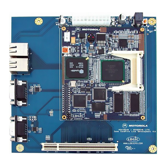
Page 7: Mini Itx Lite Baseboard Connection Diagram
Mini ITX Lite Baseboard Connection Diagram Figure 2.2 – Connection Diagram for the ITX Baseboard Connection Diagram Details: 1. CAN Port 2. Serial Port 3. Ethernet Ports • Ethernet Port 1 (top in this image) • Ethernet Port 0 (bottom in this image) 4. -
Page 8: P&E Shielded Bdm Interface Connection Diagram
P&E Shielded BDM Interface Connection Diagram Please ensure that your P&E Shielded BDM Interface is properly connected. Figure 2.3 – P&E Shielded BDM Interface Properly Connected to the Fire Engine Zoom ColdFire Lite QuickStart Guide... -
Page 9: Quickstart
QuickStart Inserting the Fire Engine into the Mini-ITX Lite Baseboard Insert the Fire Engine into the Hirose connectors on the Mini-ITX Lite Baseboard. 1) Position the Fire Engine’s four white 100 pin Hirose connectors directly above the four mating Hirose connectors on the ITX Baseboard (see picture below). 2) Firmly press the Fire Engine downward on each connector until it is fully seated. -
Page 10: Connecting The Mini-Itx Lite Baseboard To Your Pc
Connecting the Mini-ITX Lite Baseboard to your PC Figure 3.2 – Connecting the Mini ITX Lite Baseboard to your PC 1. Connect the null-modem serial cable (supplied in the kit) to the serial port connector on the baseboard and to a COM port on the Host PC. 2. -
Page 11: Test Drive The Zoom Coldfire Lite Development Kit
Test Drive the Zoom ColdFire LITE Development Kit Terminal Emulation Installation The Zoom ColdFire LITE Developer Kit is designed to communicate with terminal emulation programs via the null-modem serial cable included, using the following settings: 19200 baud, 8- data-bits, 1-stop-bit, no-parity, and no-flow-control. The terminal emulation program must support binary transfers in order to download software to the kit. -
Page 12: Dbug Rom Monitor Power-Up
In the terminal program you should now see a dBUG screen presenting text similar to this: External Reset ColdFire MCF548X on the M5485EVB Firmware v3b.1a.1a (Built on Jul 13 2004 13:22:36) Copyright 1995-2004 Freescale Semiconductor, Inc. Check ColdFire website for dBUG updates Enter 'help' for help. dBUG>... -
Page 13: Using The Development Kit With The P&E Coldfire Lite Bdm Interface
In the terminal program you should now see a LogicLoader screen presenting text similar to the one below. Please refer to Section 11 for important information about the CPLD code. dBUG> go ff840000 spi not initialized: cpld code not detected. serial eeprom not initialized: cpld code not detected. - Page 14 1. You must remove the BDM enclosure to change the jumper as shown below. Figure 4.2 – Remove BDM Enclosure to change the Jumper 2. Next, configure your jumper as presented in the figure below. Figure 4.3 – Jumper Setting for GNU Cross Development Toolchain Zoom ColdFire Lite QuickStart Guide...
-
Page 15: Sample Application
Connecting with the GDB Debugger Please follow the steps below to connect your board with the GDB debugger. Install Cygwin and the GNU Cross Development Tool Chain provided on the CD-ROM or downloaded for free from Logic’s website at the following location: https://www.logicpd.com/auth/login.php. -
Page 16: Jumper/Switch Table
Jumper/Switch Table The following table describes the function of the jumpers on the Fire Engine. Table 5.1: Jumper Switch Table Jumper Settings Function CAN Port 1 Non-terminated Jmp 2-4 data line CAN Port 1 Terminated data Jmp 4-6 line CAN Port 1 Non-terminated Jmp 1-3 data line CAN Port 1 Terminated data... -
Page 17: Product Notices
Product Notices The Zoom ColdFire LITE Development Kit being sold by Logic is intended for ENGINEERING DEVELOPMENT OR EVALUATION PURPOSES ONLY. As such, the goods being provided may not be complete in terms of required design, marketing, and/or manufacturing related protective considerations, including product safety measures typically found in the end product incorporating the goods. -
Page 18: Ordering Information
Ordering Information Zoom ColdFire LITE Development Kits, Fire Engines, and Display Kits are available direct from Freescale or their worldwide distributors. Zoom ColdFire LITE Development Kits M5474EVB includes M5475CFE Fire Engine M5484EVB includes M5485CFE Fire Engine Fire Engine Configurations Boot Graphics Freescale PN Flash... -
Page 19: Support
Support The Zoom ColdFire LITE Development Kit is a Freescale part number. Technical support should be handled as follows: 1. First, contact your local Freescale sales office if there are any issues or questions. 2. Second, use Freescale’s Technical Information Center. See enclosed information card in box. http:// freescale.com/semiconductors 3. -
Page 20: Zoom Display Kits
Zoom Display Kits Display Kits are ideal for embedded solutions requiring a graphical user interface. Logic offers a variety of display sizes (3.5”, 6.4”, 12.1”), resolutions (QVGA, VGA, SVGA), and types (TFT, etc.). Zoom Display Kits are sold separately. Visit Logic’s website at http://www.logicpd.com for a complete listing of Display Kits and accessories for the ColdFire LITE Development Kits. -
Page 21: Fire Engine Cpld Important Notice
Fire Engine CPLD Important Notice The CPLD device on the Fire Engine included in the M547xEVB and M548xEVB development kits does not contain any CPLD code. The CPLD is not required to run the microprocessor memory architecture or on-chip peripherals. Logic has developed additional features in the CPLD that provide the following interfaces and functionality: ISA-Like bus interface... -
Page 22: Troubleshooting
Troubleshooting Q: My board does not respond with BDM interface connected, what can I do? A: Try pressing the System Reset button (see Figure 2.2). Q: My CompactFlash connector does not work, why? A: See Section 11 regarding CompactFlash functionality. Q: How do I use CPLD devices on the board? A: See Section 11 for a list of functionality and options for obtaining CPLD code.
Need help?
Do you have a question about the Logic Zoom ColdFire LITE Series and is the answer not in the manual?
Questions and answers