
Related Manuals for Freescale Semiconductor MCF52100


Summary of Contents for Freescale Semiconductor MCF52100
- Page 1 ® MCF52110 ColdFire Integrated Microcontroller Reference Manual Devices Supported: MCF52110 MCF52100 Document Number: MCF52110RM Rev. 1 06/2007...
- Page 2 Freescale Semiconductor product could Asia/Pacific: create a situation where personal injury or death may occur. Should Buyer Freescale Semiconductor Hong Kong Ltd.
-
Page 3: Table Of Contents
2.14 Pulse-Width Modulator Signals ..........2-10 MCF52110 ColdFire® Integrated Microcontroller Reference Manual, Rev. 1 Freescale Semiconductor Preliminary... - Page 4 5.1.2 Features ............. 5-1 MCF52110 ColdFire® Integrated Microcontroller Reference Manual, Rev. 1 Freescale Semiconductor Preliminary...
- Page 5 Functional Description ............7-6 MCF52110 ColdFire® Integrated Microcontroller Reference Manual, Rev. 1 Freescale Semiconductor Preliminary...
- Page 6 10.6.2 Reset Control Flow ........... 10-7 MCF52110 ColdFire® Integrated Microcontroller Reference Manual, Rev. 1 Freescale Semiconductor Preliminary...
- Page 7 13.3 Features ..............13-2 MCF52110 ColdFire® Integrated Microcontroller Reference Manual, Rev. 1 Freescale Semiconductor Preliminary...
- Page 8 16.1 Introduction ..............16-1 MCF52110 ColdFire® Integrated Microcontroller Reference Manual, Rev. 1 Freescale Semiconductor Preliminary...
- Page 9 18.6 Initialization/Application Information ..........18-8 MCF52110 ColdFire® Integrated Microcontroller Reference Manual, Rev. 1 Freescale Semiconductor Preliminary...
- Page 10 20.6.17Pulse Accumulator Counter Register (GPTPACNT) ......20-15 MCF52110 ColdFire® Integrated Microcontroller Reference Manual, Rev. 1 Freescale Semiconductor viii...
- Page 11 22.1.3 Features ............22-2 MCF52110 ColdFire® Integrated Microcontroller Reference Manual, Rev. 1 Freescale Semiconductor Preliminary...
- Page 12 23.5 Initialization/Application Information ......... . . 23-26 MCF52110 ColdFire® Integrated Microcontroller Reference Manual, Rev. 1 Freescale Semiconductor Preliminary...
- Page 13 25.4.5 Sample Disable Register (ADSDIS) ........25-10 MCF52110 ColdFire® Integrated Microcontroller Reference Manual, Rev. 1 Freescale Semiconductor Preliminary...
- Page 14 26.3.2 PWM Channel Timers ..........26-15 MCF52110 ColdFire® Integrated Microcontroller Reference Manual, Rev. 1 Freescale Semiconductor Preliminary...
- Page 15 28.3.1 Instruction Shift Register (IR) ......... . . 28-4 MCF52110 ColdFire® Integrated Microcontroller Reference Manual, Rev. 1 Freescale Semiconductor xiii...
- Page 16 28.5.2 Nonscan Chain Operation ..........28-10 MCF52110 ColdFire® Integrated Microcontroller Reference Manual, Rev. 1 Freescale Semiconductor Preliminary...
-
Page 17: Mcf52110 Coldfire® Integrated Microcontroller Reference Manual,
This chapter provides an overview of the major features and functional components of the MCF52110 ® family of microcontrollers. The MCF52110 family is a highly integrated implementation of the ColdFire family of reduced instruction set computing (RISC) microcontrollers that also includes the MCF52100. The differences between these parts are summarized in Table 1-1. -
Page 18: Mcf52110 Family Configurations
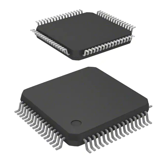
Block Diagram The superset device in the MCF52110 family comes in a 100-lead leaded quad flat package (LQFP). Figure 1-1 shows a top-level block diagram of the MCF52110. MCF52110 ColdFire® Integrated Microcontroller Reference Manual, Rev. 1 Freescale Semiconductor Preliminary... -
Page 19: Part Numbers And Packaging
CIM_IBO Watchdog STBY Edge PLL OCO PIT0 PIT1 Port CLKGEN EXTAL XTAL CLKOUT GPT[3:0] IRQ[7:1] Figure 1-1. MCF52110 Block Diagram Part Numbers and Packaging Table 1-2. Part Number Summary MCF52110 ColdFire® Integrated Microcontroller Reference Manual, Rev. 1 Freescale Semiconductor Preliminary... -
Page 20: Features
Overview Part Number Flash / SRAM Key Features Package Speed MCF52100 64 Kbytes / 16 Kbytes 2 UARTs, 2 I C, QSPI, A/D, DMA, 64 LQFP/QFN 66, 80 MHz 16-/32-bit/PWM Timers 81 MAPBGA MCF52110 128 Kbytes / 16 Kbytes 3 UARTs, 2 I... - Page 21 — Free run and restart modes — Maskable interrupts on input capture or output compare — DMA trigger capability on input capture or output compare • Four-channel general purpose timer MCF52110 ColdFire® Integrated Microcontroller Reference Manual, Rev. 1 Freescale Semiconductor Preliminary...
- Page 22 — Two to 10 MHz reference frequency for normal PLL mode with a pre-divider programmable from 1 to 8 — System can be clocked from PLL or directly from crystal oscillator or relaxation oscillator — Low power modes supported MCF52110 ColdFire® Integrated Microcontroller Reference Manual, Rev. 1 Freescale Semiconductor Preliminary...
- Page 23 — Unique part identification number and part revision number • General purpose I/O interface — Up to 56 bits of general purpose I/O — Bit manipulation supported via set/clear functions MCF52110 ColdFire® Integrated Microcontroller Reference Manual, Rev. 1 Freescale Semiconductor Preliminary...
-
Page 24: V2 Core Overview
ALLPST. This signal is the logical AND of the processor status (PST[3:0]) signals and is useful for detecting when the processor is in a halted state (PST[3:0] = 1111). MCF52110 ColdFire® Integrated Microcontroller Reference Manual, Rev. 1 Freescale Semiconductor Preliminary... -
Page 25: Jtag
The CFM interfaces to the ColdFire core through an optimized read-only memory controller that supports interleaved accesses from the 2-cycle flash memory arrays. A backdoor MCF52110 ColdFire® Integrated Microcontroller Reference Manual, Rev. 1 Freescale Semiconductor Preliminary... -
Page 26: Power Management
Both ADCs may be required during a scan, depending on the inputs to be sampled. MCF52110 ColdFire® Integrated Microcontroller Reference Manual, Rev. 1 1-10 Freescale Semiconductor Preliminary... -
Page 27: Dma Timers (Dtim0–Dtim3)
The MCF52110 has an 8-channel, 8-bit PWM timer. Each channel has a programmable period and duty cycle as well as a dedicated counter. Each of the modulators can create independent continuous waveforms MCF52110 ColdFire® Integrated Microcontroller Reference Manual, Rev. 1 Freescale Semiconductor 1-11 Preliminary... -
Page 28: Software Watchdog Timer
The reset controller determines the source of reset, asserts the appropriate reset signals to the system, and keeps track of what caused the last reset. There are seven sources of reset: MCF52110 ColdFire® Integrated Microcontroller Reference Manual, Rev. 1 1-12 Freescale Semiconductor Preliminary... -
Page 29: Gpio
Nearly all pins on the MCF52110 have general purpose I/O capability and are grouped into 8-bit ports. Some ports do not use all eight bits. Each port has registers that configure, monitor, and control the port pins. MCF52110 ColdFire® Integrated Microcontroller Reference Manual, Rev. 1 Freescale Semiconductor 1-13 Preliminary... - Page 30 Overview MCF52110 ColdFire® Integrated Microcontroller Reference Manual, Rev. 1 1-14 Freescale Semiconductor Preliminary...
-
Page 31: Introduction
Active-low signals, such as SRAS and TA, are indicated with an overbar. Overview Figure 2-1 shows the block diagram of the device with the signal interface. MCF52110 ColdFire® Integrated Microcontroller Reference Manual, Rev. 1 Freescale Semiconductor Preliminary... -
Page 32: Pin Functions
(2K×32)×2 AN[7:0] RSTO (16K×16)×4 Backup CIM_IBO Watchdog STBY Edge PLL OCO PIT0 PIT1 Port CLKGEN EXTAL XTAL CLKOUT GPT[3:0] IRQ[7:1] Figure 2-1. Block Diagram with Signal Interfaces Pin Functions MCF52110 ColdFire® Integrated Microcontroller Reference Manual, Rev. 1 Freescale Semiconductor Preliminary... - Page 33 Table 2-1. Pin Functions by Primary and Alternate Purpose Drive Primary Secondary Tertiary Quaternary Slew Rate / Pull-up / Pin on Pin on 81 Pin on 64 Strength / Group Function Function Function Function Control Pull-down 100 LQFP MAPBGA LQFP/QFN Control —...
- Page 34 Table 2-1. Pin Functions by Primary and Alternate Purpose (continued) Drive Primary Secondary Tertiary Quaternary Slew Rate / Pull-up / Pin on Pin on 81 Pin on 64 Strength / Group Function Function Function Function Control Pull-down 100 LQFP MAPBGA LQFP/QFN Control Interrupts...
- Page 35 Table 2-1. Pin Functions by Primary and Alternate Purpose (continued) Drive Primary Secondary Tertiary Quaternary Slew Rate / Pull-up / Pin on Pin on 81 Pin on 64 Strength / Group Function Function Function Function Control Pull-down 100 LQFP MAPBGA LQFP/QFN Control QSPI...
- Page 36 Table 2-1. Pin Functions by Primary and Alternate Purpose (continued) Drive Primary Secondary Tertiary Quaternary Slew Rate / Pull-up / Pin on Pin on 81 Pin on 64 Strength / Group Function Function Function Function Control Pull-down 100 LQFP MAPBGA LQFP/QFN Control UART 1...
-
Page 37: Reset Signals
Test TEST Reserved for factory testing only and in normal modes of operation should be connected to VSS to prevent unintentional activation of test functions. MCF52110 ColdFire® Integrated Microcontroller Reference Manual, Rev. 1 Freescale Semiconductor Preliminary... -
Page 38: External Interrupt Signals
Provides the serial clock from the QSPI. The polarity and phase of QSPI_CLK are programmable. Synchronous Peripheral QSPI_CS[3:0] QSPI peripheral chip selects that can be programmed to be active Chip Selects high or low. MCF52110 ColdFire® Integrated Microcontroller Reference Manual, Rev. 1 Freescale Semiconductor Preliminary... -
Page 39: Uart Module Signals
Table 2-10. DMA Timer Signals Signal Name Abbreviation Function DMA Timer Input DTINn Event input to the DMA timer modules. DMA Timer Output DTOUTn Programmable output from the DMA timer modules. MCF52110 ColdFire® Integrated Microcontroller Reference Manual, Rev. 1 Freescale Semiconductor Preliminary... -
Page 40: Adc Signals
Test Clock TCLK Used to synchronize the JTAG logic. Test Mode Select Used to sequence the JTAG state machine. TMS is sampled on the rising edge of TCLK. MCF52110 ColdFire® Integrated Microcontroller Reference Manual, Rev. 1 2-10 Freescale Semiconductor Preliminary... - Page 41 The CLKOUT signal can be used by the development system to know when to sample PST[3:0]. All Processor Status ALLPST Logical AND of PST[3.0] Outputs MCF52110 ColdFire® Integrated Microcontroller Reference Manual, Rev. 1 Freescale Semiconductor 2-11 Preliminary...
-
Page 42: Ezport Signal Descriptions
Positive Supply These pins supply positive power to the core logic. Ground This pin is the negative supply (ground) to the chip. MCF52110 ColdFire® Integrated Microcontroller Reference Manual, Rev. 1 2-12 Freescale Semiconductor Preliminary... -
Page 43: Introduction
The instruction fetch pipeline (IFP) is a two-stage pipeline for prefetching instructions. The prefetched instruction stream is then gated into the two-stage operand execution pipeline (OEP), which decodes the MCF52110 ColdFire® Integrated Microcontroller Reference Manual, Rev. 1 Freescale Semiconductor Preliminary... -
Page 44: Memory Map/Register Description
8-bit condition code register (CCR) • MAC registers (described fully in Chapter 4, “Multiply-Accumulate Unit (MAC)”): — One 32-bit accumulator(ACC) register — One 16-bit mask register (MASK) — 8-bit Status register (MACSR) MCF52110 ColdFire® Integrated Microcontroller Reference Manual, Rev. 1 Freescale Semiconductor Preliminary... - Page 45 User/Supervisor A7 Stack Pointer Contents of 3.2.3/3-4 (OTHER_A7) location 0x0000_0000 0x801 Vector Base Register (VBR) 0x0000_0000 3.2.6/3-6 0x80E Status Register (SR) 0x27-- 3.2.7/3-7 0xC04 Flash Base Address Register 0x0000_0000 3.2.8/3-8 (FLASHBAR) MCF52110 ColdFire® Integrated Microcontroller Reference Manual, Rev. 1 Freescale Semiconductor Preliminary...
-
Page 46: Data Registers (D0–D7)
(SSP) and the user stack pointer (USP). The hardware implementation of these two programmable-visible 32-bit registers does not identify one as the SSP and the other as the USP. Instead, MCF52110 ColdFire® Integrated Microcontroller Reference Manual, Rev. 1 Freescale Semiconductor Preliminary... -
Page 47: Condition Code Register (Ccr)
The extend bit (X) is also used as an input operand during multiprecision arithmetic computations. The CCR register must be explicitly loaded after reset and before any compare (CMP), Bcc, or Scc instructions are executed. MCF52110 ColdFire® Integrated Microcontroller Reference Manual, Rev. 1 Freescale Semiconductor Preliminary... -
Page 48: Program Counter (Pc)
The VBR contains the base address of the exception vector table in memory. To access the vector table, the displacement of an exception vector is added to the value in VBR. The lower 20 bits of the VBR are MCF52110 ColdFire® Integrated Microcontroller Reference Manual, Rev. 1 Freescale Semiconductor Preliminary... -
Page 49: Status Register (Sr)
1 Supervisor mode Master/interrupt state. Bit is cleared by an interrupt exception and software can set it during execution of the RTE or move to SR instructions. Reserved, must be cleared. MCF52110 ColdFire® Integrated Microcontroller Reference Manual, Rev. 1 Freescale Semiconductor Preliminary... -
Page 50: Memory Base Address Registers (Rambar, Flashbar)
A more detailed view of the hardware structure within the two pipelines is presented in Figure 3-9 Figure 3-10 below. In these diagrams, the internal structure of the instruction fetch and operand execution pipelines is shown: MCF52110 ColdFire® Integrated Microcontroller Reference Manual, Rev. 1 Freescale Semiconductor Preliminary... - Page 51 IFP during the cycle. If the accessed data is not present in a local memory (e.g., an instruction cache miss, or an external access cycle is required), the IFP is stalled in MCF52110 ColdFire® Integrated Microcontroller Reference Manual, Rev. 1 Freescale Semiconductor Preliminary...
- Page 52 For memory-to-register (embedded-load) instructions, the instruction is effectively staged through the OEP twice with a basic execution time of three cycles. First, the instruction is decoded and the components MCF52110 ColdFire® Integrated Microcontroller Reference Manual, Rev. 1 3-10 Freescale Semiconductor Preliminary...
- Page 53 Operand Execution Pipeline DSOC AGEX <ea>y Core Bus Address Opword Extension 1 Core Bus Extension 2 Write Data Core Bus Read Data Figure 3-12. V2 OEP Embedded-Load Part 1 MCF52110 ColdFire® Integrated Microcontroller Reference Manual, Rev. 1 Freescale Semiconductor 3-11 Preliminary...
- Page 54 <ea>x = (d16,Ax), i.e., a 16-bit signed displacement added to a base register Ax. For read-modify-write instructions, the pipeline effectively combines an embedded-load with a store operation for a three-cycle execution time. MCF52110 ColdFire® Integrated Microcontroller Reference Manual, Rev. 1 3-12 Freescale Semiconductor Preliminary...
- Page 55 In these diagrams, the x-axis represents time, and the various instruction operations are shown progressing down the operand execution pipeline. MCF52110 ColdFire® Integrated Microcontroller Reference Manual, Rev. 1 Freescale Semiconductor 3-13 Preliminary...
-
Page 56: Instruction Set Architecture (Isa_A+)
(Dn[0]), searching for the first set bit. The data register is then loaded with the offset count from bit 31 where the first set bit appears. MCF52110 ColdFire® Integrated Microcontroller Reference Manual, Rev. 1 3-14 Freescale Semiconductor Preliminary... -
Page 57: Exception Processing Overview
After the instruction fetch for the first opcode of the handler has initiated, exception processing terminates and normal instruction processing continues in the handler. MCF52110 ColdFire® Integrated Microcontroller Reference Manual, Rev. 1 Freescale Semiconductor 3-15 Preliminary... - Page 58 For more details see ColdFire Family Programmer’s Reference Manual. MCF52110 ColdFire® Integrated Microcontroller Reference Manual, Rev. 1 3-16 Freescale Semiconductor Preliminary...
- Page 59 The 8-bit vector number, vector[7:0], defines the exception type and is calculated by the processor for all internal faults and represents the value supplied by the interrupt controller in case of an interrupt. See Table 3-5. MCF52110 ColdFire® Integrated Microcontroller Reference Manual, Rev. 1 Freescale Semiconductor 3-17 Preliminary...
-
Page 60: Processor Exceptions
1 and extension word 2. The opword is further subdivided into three sections: the upper four bits segment the entire ISA into 16 instruction lines, the next 6 bits define the operation MCF52110 ColdFire® Integrated Microcontroller Reference Manual, Rev. 1 3-18 Freescale Semiconductor Preliminary... - Page 61 ColdFire cores do not provide illegal instruction detection on the extension words on any instruction, including MOVEC. 3.3.4.4 Divide-By-Zero Attempting to divide by zero causes an exception (vector 5, offset equal 0x014). MCF52110 ColdFire® Integrated Microcontroller Reference Manual, Rev. 1 Freescale Semiconductor 3-19 Preliminary...
- Page 62 Chapter 27, “Debug Module” for a detailed explanation of this program module. This exception is generated in response to a hardware breakpoint register trigger. The processor does not generate an IACK MCF52110 ColdFire® Integrated Microcontroller Reference Manual, Rev. 1 3-20 Freescale Semiconductor Preliminary...
- Page 63 SR[T] bit. This exception also clears the SR[M] bit and sets the processor’s SR[I] bit to the highest level (level 7, 0b111). Next, the VBR is initialized to zero (0x0000_0000). The control MCF52110 ColdFire® Integrated Microcontroller Reference Manual, Rev. 1 Freescale Semiconductor 3-21 Preliminary...
- Page 64 0010 V2 ColdFire core (This is the value used for this device.) 0011 V3 ColdFire core 0100 V4 ColdFire core 0101 V5 ColdFire core Else Reserved for future use. 19–16 Processor revision number. The default is 0b0000. MCF52110 ColdFire® Integrated Microcontroller Reference Manual, Rev. 1 3-22 Freescale Semiconductor Preliminary...
- Page 65 Debug module revision number. This 4-bit field defines revision level of the debug module used in the ColdFire DEBUG processor core. 0000 DEBUG_A 0001 DEBUG_B 0010 DEBUG_C 0011 DEBUG_D 0100 DEBUG_E 1001 DEBUG_B+ (This is the value used for this device.) 1011 DEBUG_D+ Else Reserved MCF52110 ColdFire® Integrated Microcontroller Reference Manual, Rev. 1 Freescale Semiconductor 3-23 Preliminary...
- Page 66 Bus size. Defines the width of the ColdFire master bus datapath. MBSZ 32-bit system bus datapath (This is the value used for this device) 64-bit system bus datapath Else Reserved MCF52110 ColdFire® Integrated Microcontroller Reference Manual, Rev. 1 3-24 Freescale Semiconductor Preliminary...
-
Page 67: Instruction Execution Timing
Thus, the maximum pipeline stall involving consecutive STORE operations is two cycles. The MOVEM instruction uses a different set of resources and this stall does not apply. MCF52110 ColdFire® Integrated Microcontroller Reference Manual, Rev. 1 Freescale Semiconductor 3-25 Preliminary... - Page 68 3(1/1) 3(1/1) 4(1/1)) 3(1/1) (Ay)+ 3(1/0) 3(1/1) 3(1/1) 3(1/1) 3(1/1) 4(1/1)) 3(1/1) -(Ay) 3(1/0) 3(1/1) 3(1/1) 3(1/1) 3(1/1) 4(1/1)) 3(1/1) (d16,Ay) 3(1/0) 3(1/1) 3(1/1) 3(1/1) 3(1/1) — — MCF52110 ColdFire® Integrated Microcontroller Reference Manual, Rev. 1 3-26 Freescale Semiconductor Preliminary...
- Page 69 1(0/0) 1(0/1) 1(0/1) 1(0/1) 1(0/1) 2(0/1) 1(0/1) — clr.w <ea> 1(0/0) 1(0/1) 1(0/1) 1(0/1) 1(0/1) 2(0/1) 1(0/1) — clr.l <ea> 1(0/0) 1(0/1) 1(0/1) 1(0/1) 1(0/1) 2(0/1) 1(0/1) — MCF52110 ColdFire® Integrated Microcontroller Reference Manual, Rev. 1 Freescale Semiconductor 3-27 Preliminary...
- Page 70 2(0/0) 4(1/1) 4(1/1) 4(1/1) 4(1/1) 5(1/1) 4(1/1) — bclr #imm,<ea> 2(0/0) 4(1/1) 4(1/1) 4(1/1) 4(1/1) — — — bset Dy,<ea> 2(0/0) 4(1/1) 4(1/1) 4(1/1) 4(1/1) 5(1/1) 4(1/1) — MCF52110 ColdFire® Integrated Microcontroller Reference Manual, Rev. 1 3-28 Freescale Semiconductor Preliminary...
- Page 71 2(0/1) — — — — — — — move.l Ay,USP 3(0/0) — — — — — — — move.l USP,Ax 3(0/0) — — — — — — — MCF52110 ColdFire® Integrated Microcontroller Reference Manual, Rev. 1 Freescale Semiconductor 3-29 Preliminary...
- Page 72 4(1/0) — — — mac.w Ry, Rx 1(0/0) — — — — — — — mac.w Ry, Rx, <ea>, Rw — 2(1/0) 2(1/0) 2(1/0) 2(1/0) — — — MCF52110 ColdFire® Integrated Microcontroller Reference Manual, Rev. 1 3-30 Freescale Semiconductor Preliminary...
- Page 73 4(0/0) 3(0/0) — <ea> — 3(0/1) — — 3(0/1) 4(0/1) 3(0/1) — — — 10(2/0) — — — — — — — 5(1/0) — — — — — MCF52110 ColdFire® Integrated Microcontroller Reference Manual, Rev. 1 Freescale Semiconductor 3-31 Preliminary...
- Page 74 ColdFire Core Table 3-19. Bcc Instruction Execution Times Forward Forward Backward Backward Opcode Taken Not Taken Taken Not Taken 3(0/0) 1(0/0) 2(0/0) 3(0/0) MCF52110 ColdFire® Integrated Microcontroller Reference Manual, Rev. 1 3-32 Freescale Semiconductor Preliminary...
-
Page 75: Introduction
The MAC is an extension of the basic multiplier in most microprocessors. It is typically implemented in hardware within an architecture and supports rapid execution of signal processing algorithms in fewer MCF52110 ColdFire® Integrated Microcontroller Reference Manual, Rev. 1 Freescale Semiconductor Preliminary... -
Page 76: Memory Map/Register Definition
Operational mode bits control whether operands are signed or unsigned and whether they are treated as integers or fractions. These bits also control the overflow/saturation mode and the way in which rounding is performed. Negative, zero, and overflow condition flags are also provided. MCF52110 ColdFire® Integrated Microcontroller Reference Manual, Rev. 1 Freescale Semiconductor Preliminary... - Page 77 Zero. Set if the result equals zero, otherwise cleared. This bit is affected only by MAC, MSAC, and load operations; it is not affected by MULS and MULU instructions. MCF52110 ColdFire® Integrated Microcontroller Reference Manual, Rev. 1 Freescale Semiconductor Preliminary...
-
Page 78: Mask Register (Mask)
Ry,RxSF,<ea>y&,Rw The & operator enables the MASK use and causes bit 5 of the extension word to be set. The exact algorithm for the use of MASK is: MCF52110 ColdFire® Integrated Microcontroller Reference Manual, Rev. 1 Freescale Semiconductor Preliminary... -
Page 79: Accumulator Register (Acc)
Reset – – – – – – – – – – – – – – – – – – – – – – – – – – – – – – – – Figure 4-4. Accumulator Register (ACC) MCF52110 ColdFire® Integrated Microcontroller Reference Manual, Rev. 1 Freescale Semiconductor Preliminary... -
Page 80: Functional Description
The programming model includes a mask register (MASK), which can optionally be used to generate an operand address during MAC + MOVE instructions. The register application with auto-increment addressing mode supports efficient implementation of circular data queues for memory operands. MCF52110 ColdFire® Integrated Microcontroller Reference Manual, Rev. 1 Freescale Semiconductor Preliminary... -
Page 81: Fractional Operation Mode
In particular, any result rounding modes must be disabled during the save/restore process so the exact bit-wise contents of the MAC registers are accessed. Consider the memory structure containing the MAC programming model: struct macState { int acc; int mask; MCF52110 ColdFire® Integrated Microcontroller Reference Manual, Rev. 1 Freescale Semiconductor Preliminary... -
Page 82: Mac Instruction Set Summary
Ry,RxSF,Rw operand Load Accumulator Loads the accumulator with a 32-bit operand move.l {Ry,#imm},ACC Store Accumulator Writes the contents of the accumulator to a CPU register move.l ACC,Rx MCF52110 ColdFire® Integrated Microcontroller Reference Manual, Rev. 1 Freescale Semiconductor Preliminary... -
Page 83: Mac Instruction Execution Times
32-bit value (this applies to 32 × 32 integer operations only) or if the combination of the product with the accumulator cannot be represented in the given number of bits. This indicator is MCF52110 ColdFire® Integrated Microcontroller Reference Manual, Rev. 1 Freescale Semiconductor Preliminary... - Page 84 = 0x7fff_ffff else result[31:0] = 0x8000_0000 else if (MACSR.OMC == 1) then /* overflowed MAC, saturationMode enabled */ if (product[63] == 1) then result[31:0] = 0x8000_0000 MCF52110 ColdFire® Integrated Microcontroller Reference Manual, Rev. 1 4-10 Freescale Semiconductor Preliminary...
- Page 85 = 0x8000_0000 /* transfer the result to the accumulator */ acc[31:0] = result[31:0] MACSR.N = result[31] if (result[31:0] == 0x0000_0000) then MACSR.Z = 1 else MACSR.Z = 0 MCF52110 ColdFire® Integrated Microcontroller Reference Manual, Rev. 1 Freescale Semiconductor 4-11 Preliminary...
- Page 86 /* transfer the result to the accumulator */ acc[31:0] = result[31:0] MACSR.N = result[31] if (result[31:0] == 0x0000_0000) then MACSR.Z = 1 else MACSR.Z = 0 break; case 2: /* unsigned integers */ MCF52110 ColdFire® Integrated Microcontroller Reference Manual, Rev. 1 4-12 Freescale Semiconductor Preliminary...
-
Page 87: If (Macsr.omc == 0 || Macsr.v == 0) Then
2: /* reserved encoding */ break; case 3: /* SF = “>> 1” */ product[31:0] = {0, product[31:1]} break; /* combine with accumulator */ if (MACSR.V == 0) MCF52110 ColdFire® Integrated Microcontroller Reference Manual, Rev. 1 Freescale Semiconductor 4-13 Preliminary... -
Page 88: Check For Accumulation Overflow
= 0xffff_ffff /* transfer the result to the accumulator */ acc[31:0] = result[31:0] MACSR.N = result[31] if (result[31:0] == 0x0000_0000) then MACSR.Z = 1 else MACSR.Z = 0 break;} MCF52110 ColdFire® Integrated Microcontroller Reference Manual, Rev. 1 4-14 Freescale Semiconductor Preliminary... -
Page 89: Mcf52110 Coldfire® Integrated Microcontroller Reference Manual, Rev. 1
Byte, word, and longword address capabilities Memory Map/Register Description The SRAM programming model shown in Table 5-1 includes a description of the SRAM base address register (RAMBAR), SRAM initialization, and power management. MCF52110 ColdFire® Integrated Microcontroller Reference Manual, Rev. 1 Freescale Semiconductor Preliminary... -
Page 90: Sram Base Address Register (Rambar)
Base Address. Defines the 0-modulo-32K base address of the SRAM module. By programming this field, the SRAM may be located on any 32-Kbyte boundary. 13–12 Reserved, should be cleared. MCF52110 ColdFire® Integrated Microcontroller Reference Manual, Rev. 1 Freescale Semiconductor Preliminary... -
Page 91: Initialization/Application Information
If the SRAM requires initialization with instructions or data, perform the following steps: 1. Load the RAMBAR, mapping the SRAM module to the desired location within the address space. MCF52110 ColdFire® Integrated Microcontroller Reference Manual, Rev. 1 Freescale Semiconductor Preliminary... -
Page 92: Sram Initialization Code
Table 5-3 shows examples of typical RAMBAR settings. Table 5-3. Typical RAMBAR Setting Examples Data Contained in SRAM RAMBAR[7:0] Instruction Only 0x2B Data Only 0x35 Instructions and Data 0x21 MCF52110 ColdFire® Integrated Microcontroller Reference Manual, Rev. 1 Freescale Semiconductor Preliminary... -
Page 93: Introduction
POR. Thus, if the relaxation oscillator is selected as the timer’s input source, subsequent attempts to select the relaxation oscillator as the system clock’s source are blocked until the MCF52110 ColdFire® Integrated Microcontroller Reference Manual, Rev. 1 Freescale Semiconductor Preliminary... -
Page 94: Rtc Mode
In wait and doze modes, the system clocks to the peripherals are enabled and the clocks to the CPU and SRAM are stopped. Each module can disable its clock locally at the module level. MCF52110 ColdFire® Integrated Microcontroller Reference Manual, Rev. 1 Freescale Semiconductor Preliminary... -
Page 95: Block Diagram
RFD value plus one before entering stop mode. In external clock mode, there are no wakeup periods for oscillator startup or PLL lock. Block Diagram Figure 6-1 shows a block diagram of the entire clock module. MCF52110 ColdFire® Integrated Microcontroller Reference Manual, Rev. 1 Freescale Semiconductor Preliminary... -
Page 96: Signal Descriptions
Figure 6-1. Clock Module Block Diagram Signal Descriptions The clock module signals are summarized in Table 6-2 and a brief description follows. For more detailed information, refer to Chapter 2, “Signal Descriptions.” MCF52110 ColdFire® Integrated Microcontroller Reference Manual, Rev. 1 Freescale Semiconductor Preliminary... -
Page 97: Extal
PLL in normal mode, clock driven by on-chip oscillator PLL in normal mode, clock driven by external crystal 6.6.5 RSTO The RSTO pin is asserted by one of the following: • Internal system reset signal MCF52110 ColdFire® Integrated Microcontroller Reference Manual, Rev. 1 Freescale Semiconductor Preliminary... -
Page 98: Memory Map And Registers
The contents of BWCR are reset only during Power-On Reset; they are preserved during a warm reset. Section 8.2.1, “Peripheral Power Management Registers (PPMRH, PPMRL).” 6.7.1 Register Descriptions This subsection provides a description of the clock module registers. MCF52110 ColdFire® Integrated Microcontroller Reference Manual, Rev. 1 Freescale Semiconductor Preliminary... - Page 99 MFD[2:0] bits or entering stop mode with the PLL disabled. 0 No reset on loss of lock 1 Reset on loss of lock Note: In external clock mode, the LOLRE bit has no effect. MCF52110 ColdFire® Integrated Microcontroller Reference Manual, Rev. 1 Freescale Semiconductor Preliminary...
- Page 100 Note: In external clock mode, the LOCEN bit has no effect Disable CLKOUT determines whether CLKOUT is driven. Setting the DISCLK bit holds CLKOUT low. DISCLK 0 CLKOUT enabled 1 CLKOUT disabled MCF52110 ColdFire® Integrated Microcontroller Reference Manual, Rev. 1 Freescale Semiconductor Preliminary...
- Page 101 See note 1 See note 2 See note 2 Note: 1. Reset state determined during reset configuration. 2. See the LOCKS and LOCK bit descriptions. Figure 6-3. Synthesizer Status Register (SYNSR) MCF52110 ColdFire® Integrated Microcontroller Reference Manual, Rev. 1 Freescale Semiconductor Preliminary...
- Page 102 1 Loss-of-clock detected since exiting reset or oscillator not yet recovered from exit from stop mode with FWKUP = 1 Note: The LOCS flag is always 0 in external clock mode. 1–0 Reserved, should be cleared. MCF52110 ColdFire® Integrated Microcontroller Reference Manual, Rev. 1 6-10 Freescale Semiconductor Preliminary...
- Page 103 4 bit field). The clock change takes effect with the next rising edge of the system clock. IPSBAR Access: Supervisor read/write Offset: 0x12_0007 (LPDR) — — — — LPD3 LPD2 LPD1 LPD0 Reset: Figure 6-5. Low-Power Divider Register (LPDR) MCF52110 ColdFire® Integrated Microcontroller Reference Manual, Rev. 1 Freescale Semiconductor 6-11 Preliminary...
- Page 104 When switching the clock source to the relaxation oscillator, OCHR[OCOEN] should be set before OSCSEL is set. Similarly, when switching the clock source to the external oscillator, OCLR[OSCEN] should be set before OSCSEL is cleared. MCF52110 ColdFire® Integrated Microcontroller Reference Manual, Rev. 1 6-12 Freescale Semiconductor Preliminary...
- Page 105 Source of PLL input/bypass clock Primary oscillator (default) Relaxation oscillator Secondary oscillator 6.7.1.7 Oscillator Control High Register (OCHR) The OCHR is used to enable and configure the relaxation oscillator. MCF52110 ColdFire® Integrated Microcontroller Reference Manual, Rev. 1 Freescale Semiconductor 6-13 Preliminary...
- Page 106 OSCEN REFS LPEN RANGE Reset: See note See note 1 Figure 6-9. Oscillator Control Low Register (OCLR) The OSCEN and REFS reset states are determined during reset configuration. MCF52110 ColdFire® Integrated Microcontroller Reference Manual, Rev. 1 6-14 Freescale Semiconductor Preliminary...
- Page 107 1 RTC oscillator is enabled. The KHZEN bit selects the operating frequency range of the oscillator KHZEN 0 Oscillator operates in the kHz range. 1 Oscillator operates in the MHz range. MCF52110 ColdFire® Integrated Microcontroller Reference Manual, Rev. 1 Freescale Semiconductor 6-15 Preliminary...
- Page 108 The BWCR is reset to these values only after a Power-On Reset. The register contents are preserved during a warm reset. Table 6-15. BWCR Field Descriptions Field Description 7–2 Reserved, should be cleared. MCF52110 ColdFire® Integrated Microcontroller Reference Manual, Rev. 1 6-16 Freescale Semiconductor Preliminary...
-
Page 109: Functional Description
In external clock mode, the system is static and does not recognize reset until a clock is generated from the reference clock source selected by the CLKMOD pins (see Section 6.6.4, “CLKMOD[1:0]). MCF52110 ColdFire® Integrated Microcontroller Reference Manual, Rev. 1 Freescale Semiconductor 6-17 Preliminary... -
Page 110: System Clock Generation
Actual component values depend on crystal specifications. The following subsections describe each major block of the PLL. Refer to Figure 6-12 to see how these functional sub-blocks interact. MCF52110 ColdFire® Integrated Microcontroller Reference Manual, Rev. 1 6-18 Freescale Semiconductor Preliminary... - Page 111 The UP and DOWN signals from the PFD control whether the charge pump applies or removes charge, respectively, from the loop filter. The filter is integrated on the chip. MCF52110 ColdFire® Integrated Microcontroller Reference Manual, Rev. 1 Freescale Semiconductor 6-19 Preliminary...
- Page 112 Figure 6-13 shows the sequence for detecting locked and non-locked conditions. In external clock mode, the PLL is disabled and cannot lock. MCF52110 ColdFire® Integrated Microcontroller Reference Manual, Rev. 1 6-20 Freescale Semiconductor Preliminary...
- Page 113 To exit reset in PLL mode, the reference must be present, and the PLL must achieve lock. In external clock mode, the PLL cannot lock. Therefore, a loss of lock condition cannot occur, and the LOLRE bit has no effect. MCF52110 ColdFire® Integrated Microcontroller Reference Manual, Rev. 1 Freescale Semiconductor 6-21 Preliminary...
- Page 114 PLL attempts to operate in SCM. If successful, the PLL remains in SCM until the next reset. If the PLL cannot operate in SCM, the system remains static until the next reset. The reference and the PLL must be functioning properly to exit reset. MCF52110 ColdFire® Integrated Microcontroller Reference Manual, Rev. 1 6-22 Freescale Semiconductor Preliminary...
- Page 115 ‘LC Block LOCKS from being cleared Lose reference Stuck — — — clock or no lock regain Lose reference ‘LK ‘LC Block LOCKS clock, from being regain cleared MCF52110 ColdFire® Integrated Microcontroller Reference Manual, Rev. 1 Freescale Semiconductor 6-23 Preliminary...
- Page 116 Lose lock, Regain ‘LK ‘LC REF not entered f.b. clock, during stop; reference SCM entered clock during stop only during oscillator startup No regain Stuck — — — MCF52110 ColdFire® Integrated Microcontroller Reference Manual, Rev. 1 6-24 Freescale Semiconductor Preliminary...
- Page 117 — ‘LK ‘LC Lose lock or clock RESET — — — Reset immediately Off X Lose lock, RESET RESET — — — Reset f.b. clock, immediately reference clock MCF52110 ColdFire® Integrated Microcontroller Reference Manual, Rev. 1 Freescale Semiconductor 6-25 Preliminary...
- Page 118 — — — clock Off X Regain SCM Wakeup without disabled lock Off X Regain SCM disabled On On 0 — — Wakeup without lock Lose reference clock MCF52110 ColdFire® Integrated Microcontroller Reference Manual, Rev. 1 6-26 Freescale Semiconductor Preliminary...
- Page 119 1–>‘LC = current value is 1 until clock is regained which then is the previous value before entering stop 1–> = current value is 1 until clock is regained but CLK is never expected to regain MCF52110 ColdFire® Integrated Microcontroller Reference Manual, Rev. 1 Freescale Semiconductor 6-27 Preliminary...
- Page 120 Clock Module MCF52110 ColdFire® Integrated Microcontroller Reference Manual, Rev. 1 6-28 Freescale Semiconductor Preliminary...
- Page 121 Section 6.7.1.10, “Backup Watchdog Timer Control Register (BWCR)”). 7.1.2 Modes of Operation This section describes the operation of the BWT in low-power modes of operation. These modes are described in Chapter 8, “Power Management”. MCF52110 ColdFire® Integrated Microcontroller Reference Manual, Rev. 1 Freescale Semiconductor Preliminary...
-
Page 122: Memory Map And Register Definition
WCR and WMR are read-always/write-once, and cannot be changed until the next Power-On Reset event. This read-always/write-once register is part of the Clock Module; see Section 6.7.1.10, “Backup Watchdog Timer Control Register (BWCR),” for a detailed description. MCF52110 ColdFire® Integrated Microcontroller Reference Manual, Rev. 1 Freescale Semiconductor Preliminary... - Page 123 1 BWT stops when the device enters Doze mode. Reserved, should read 1. BWT Enable bit. This read-always/write-once bit enables the BWT. 0 BWT is disabled. 1 BWT is enabled. MCF52110 ColdFire® Integrated Microcontroller Reference Manual, Rev. 1 Freescale Semiconductor Preliminary...
- Page 124 WCNTR should be read as a whole; reading it with two 8-bit reads may not return the correct value. Writing to WCNTR has no effect and results in a normal write cycle termination. MCF52110 ColdFire® Integrated Microcontroller Reference Manual, Rev. 1 Freescale Semiconductor Preliminary...
- Page 125 BWT service field. To service the BWT, the software must write the values 0x5555 and 0xAAAA, in that order, to this field before the BWT timeout period is reached. MCF52110 ColdFire® Integrated Microcontroller Reference Manual, Rev. 1 Freescale Semiconductor Preliminary...
- Page 126 4. Write to the WCR with WCR[EN]=1 and the WAIT, DOZE, and STOP bits configured as desired. 5. To prevent a reset, service the BWT by writing 0x5555 and 0xAAAA, in that order, to the WSR before the timeout period is reached. MCF52110 ColdFire® Integrated Microcontroller Reference Manual, Rev. 1 Freescale Semiconductor Preliminary...
-
Page 127: Introduction
Addresses not assigned to a register and undefined register bits are reserved for expansion. The CCR is described in the Chip Configuration Module. It is shown here only to warn against accidental writes to this register when accessing the LPCR. MCF52110 ColdFire® Integrated Microcontroller Reference Manual, Rev. 1 Freescale Semiconductor Preliminary... -
Page 128: Peripheral Power Management Registers (Ppmrh, Ppmrl)
PPMRH definition. IPSBAR Access: read/write Offset: 0x000C (PPMRH) Reset Reset CDCFM CDPWM CDGPT Reset CDADC CDPIT1 CDPIT0 CDEPORT CDPORTS Reset Figure 8-1. Peripheral Power Management Register High (PPMRH) MCF52110 ColdFire® Integrated Microcontroller Reference Manual, Rev. 1 Freescale Semiconductor Preliminary... - Page 129 0 EPORT module clock is enabled 1 EPORT module clock is disabled Disable clock to the Ports module. CDPORTS 0 Ports module clock is enabled 1 Ports module clock is disabled MCF52110 ColdFire® Integrated Microcontroller Reference Manual, Rev. 1 Freescale Semiconductor Preliminary...
- Page 130 TMR1 module clock is enabled TMR1 module clock is disabled Disable clock to the DTIM0 module. CDTMR0 TMR0 module clock is enabled TMR0 module clock is disabled 12–11 Reserved, should be cleared. MCF52110 ColdFire® Integrated Microcontroller Reference Manual, Rev. 1 Freescale Semiconductor Preliminary...
-
Page 131: Low-Power Interrupt Control Register (Lpicr)
The following is the sequence of operations needed to enable this functionality: 1. The LPICR is programmed, setting the ENBSTOP bit (if stop mode is the desired low-power mode) and loading the appropriate interrupt priority level. MCF52110 ColdFire® Integrated Microcontroller Reference Manual, Rev. 1 Freescale Semiconductor Preliminary... - Page 132 Exit low-power mode interrupt priority level. This field defines the interrupt priority level needed to exit the XLPM_IPL low-power mode.Refer to Table 8-5. [2:0] 3–0 Reserved, should be cleared. — MCF52110 ColdFire® Integrated Microcontroller Reference Manual, Rev. 1 Freescale Semiconductor Preliminary...
-
Page 133: Peripheral Power Management Set Register (Ppmrs)
PPMRx. The data value on a register write causes the corresponding bit in the PPMRx register to be cleared. A data value of 64 to 127 provides a global clear function, forcing the entire contents of the MCF52110 ColdFire® Integrated Microcontroller Reference Manual, Rev. 1 Freescale Semiconductor Preliminary... -
Page 134: Low-Power Control Register (Lpcr)
STOP instruction is issued, and controls clock activity in this low-power mode. IPSBAR Access: read/write Offset: 0x11_0007 (LPCR) LPMD STPMD LVDSE Reset: Figure 8-6. Low-Power Control Register (LPCR) MCF52110 ColdFire® Integrated Microcontroller Reference Manual, Rev. 1 Freescale Semiconductor Preliminary... -
Page 135: Ips Bus Timeout Monitor
IPS module enable and continues to count until the bus cycle is terminated via the negation of ips_xfr_wait. If the programmed timeout value is reached before a termination, the bus monitor completes MCF52110 ColdFire® Integrated Microcontroller Reference Manual, Rev. 1 Freescale Semiconductor Preliminary... -
Page 136: Functional Description
CPU with no cycles active, powers down the system and stops all internal clocks appropriately. During stop mode, the system clock is stopped low. For entry into stop mode, the LPICR[ENBSTOP] bit must be set before a STOP instruction is issued. MCF52110 ColdFire® Integrated Microcontroller Reference Manual, Rev. 1 8-10 Freescale Semiconductor Preliminary... - Page 137 Most peripherals may be disabled by software to cease internal clock generation and remain in a static state. Each peripheral has its own specific disabling sequence (refer to each peripheral description for MCF52110 ColdFire® Integrated Microcontroller Reference Manual, Rev. 1 Freescale Semiconductor 8-11 Preliminary...
-
Page 138: Peripheral Behavior In Low-Power Modes
During this mode, the UART clocks are shut down. Coming out of stop mode returns the UARTs to operation from the state prior to the low-power mode entry. MCF52110 ColdFire® Integrated Microcontroller Reference Manual, Rev. 1 8-12 Freescale Semiconductor Preliminary... - Page 139 CPU’s status register (SR). The interrupt must also be enabled in the interrupt controller’s interrupt mask register as well as at the module from which the interrupt request would originate. MCF52110 ColdFire® Integrated Microcontroller Reference Manual, Rev. 1 Freescale Semiconductor 8-13 Preliminary...
- Page 140 In stop mode, there is no system clock available to perform the edge detect function. Thus, only the level detect logic is active (if configured) to allow any low level on the external interrupt pin to generate an interrupt (if enabled) to exit the stop mode. MCF52110 ColdFire® Integrated Microcontroller Reference Manual, Rev. 1 8-14 Freescale Semiconductor Preliminary...
-
Page 141: Summary Of Peripheral State During Low-Power Modes
Stopped Stopped SRAM Stopped Stopped Stopped Flash Stopped Stopped Stopped System Control Module Enabled Enabled Stopped DMA Controller Enabled Enabled Stopped UART0, UART1 and UART2 Enabled Enabled Stopped MCF52110 ColdFire® Integrated Microcontroller Reference Manual, Rev. 1 Freescale Semiconductor 8-15 Preliminary... - Page 142 The BDM logic is clocked by a separate TCLK clock. Entering halt mode via the BDM port exits any low-power mode. Upon exit from halt mode, the previous low-power mode is re-entered and changes made in halt mode remains in effect. MCF52110 ColdFire® Integrated Microcontroller Reference Manual, Rev. 1 8-16 Freescale Semiconductor Preliminary...
-
Page 143: Introduction
Internal weak pull-down device TEST Test mode selection Internal weak pull-down device The use of external pull-up/down resistors is highly recommended. Refer to Chapter 6, “Clock Module” for more information. MCF52110 ColdFire® Integrated Microcontroller Reference Manual, Rev. 1 Freescale Semiconductor Preliminary... -
Page 144: Rcon
The reset configuration register (RCON) indicates the default chip configuration. • The chip identification register (CIR) contains a unique part number. Table 9-2. Write-Once Bits Read/Write Accessibility Configuration Read/Write Access All configurations Read-always Debug operation Write-always MCF52110 ColdFire® Integrated Microcontroller Reference Manual, Rev. 1 Freescale Semiconductor Preliminary... -
Page 145: Memory Map
Chip configuration mode. This read-only field reflects the configuration selected at reset. Mode 111 Reserved 110 Single Chip Mode 101 EzPort Mode 100 Reserved 0xx Reserved 7–0 Reserved, should be cleared. MCF52110 ColdFire® Integrated Microcontroller Reference Manual, Rev. 1 Freescale Semiconductor Preliminary... - Page 146 Offset: Reset – – – – – – – – – – – – – – – – The reset value is device-dependent. Figure 9-3. Chip Identification Register (CIR) MCF52110 ColdFire® Integrated Microcontroller Reference Manual, Rev. 1 Freescale Semiconductor Preliminary...
- Page 147 Part revision number. This number is increased by one for each new full-layer mask set of this part. The revision numbers are assigned in chronological order, beginning with zero. MCF52110 ColdFire® Integrated Microcontroller Reference Manual, Rev. 1 Freescale Semiconductor Preliminary...
- Page 148 Chip Configuration Module (CCM) MCF52110 ColdFire® Integrated Microcontroller Reference Manual, Rev. 1 Freescale Semiconductor Preliminary...
-
Page 149: Introduction
LVD control and status bits for setup and use of LVD reset or interrupt 10.3 Block Diagram Figure 10-1 illustrates the reset controller and is explained in the following sections. MCF52110 ColdFire® Integrated Microcontroller Reference Manual, Rev. 1 Freescale Semiconductor 10-1 Preliminary... -
Page 150: Signals
The reset controller programming model consists of these registers: • Reset control register (RCR)—selects reset controller functions • Reset status register (RSR)—reflects the state of the last reset source MCF52110 ColdFire® Integrated Microcontroller Reference Manual, Rev. 1 10-2 Freescale Semiconductor Preliminary... -
Page 151: Reset Control Register (Rcr)
Also, LVDF is not cleared at reset; however, it always initializes to a zero because the part does not come out of reset while in a low-power state (LVDE/LVDRE bits are enabled out of reset). MCF52110 ColdFire® Integrated Microcontroller Reference Manual, Rev. 1 Freescale Semiconductor 10-3 Preliminary... -
Page 152: Reset Status Register (Rsr)
Low voltage detect. Indicates that the last reset state was caused by an LVD reset. 1 Last reset state was caused by an LVD reset 0 Last reset state was not caused by an LVD reset MCF52110 ColdFire® Integrated Microcontroller Reference Manual, Rev. 1 10-4 Freescale Semiconductor Preliminary... -
Page 153: Functional Description
(CCR). Then, if the current bus cycle is not terminated normally, the bus monitor terminates the cycle based on the length of time programmed in the BMT field of the CCR. MCF52110 ColdFire® Integrated Microcontroller Reference Manual, Rev. 1 Freescale Semiconductor 10-5 Preliminary... - Page 154 RSTO for approximately 512 cycles. Then the device exits reset and resumes operation. 10.6.1.6 LVD Reset The LVD reset occurs when the supply input voltage, V drops below V (minimum). MCF52110 ColdFire® Integrated Microcontroller Reference Manual, Rev. 1 10-6 Freescale Semiconductor Preliminary...
-
Page 155: Reset Control Flow
10-4. In this figure, the control state boxes have been numbered, and these numbers are referred to (within parentheses) in the flow description that follows. All cycle counts given are approximate. MCF52110 ColdFire® Integrated Microcontroller Reference Manual, Rev. 1 Freescale Semiconductor 10-7 Preliminary... - Page 156 LATCH RESET STATUS ASSERT RSTO AND LATCH RESET STATUS RSTI NEGATED? PLL MODE? PLL LOCKED? WAIT 512 CLKOUT CYCLES NEGATE RSTO RCON ASSERTED? LATCH CONFIGURATION Figure 10-4. Reset Control Flow MCF52110 ColdFire® Integrated Microcontroller Reference Manual, Rev. 1 10-8 Freescale Semiconductor Preliminary...
-
Page 157: Concurrent Resets
(5, 6) for an external reset request, the cycle is terminated. The reset status bits are latched (7) and reset processing waits for the external RSTI pin to negate (8). MCF52110 ColdFire® Integrated Microcontroller Reference Manual, Rev. 1 Freescale Semiconductor 10-9 Preliminary... - Page 158 For a LVD reset, the LVD bit in the RSR is set, and the SOFT, WDR, EXT, LOC, and LOL bits are cleared to 0, even if another type of reset condition is detected during the reset sequence for LVD. MCF52110 ColdFire® Integrated Microcontroller Reference Manual, Rev. 1 10-10 Freescale Semiconductor Preliminary...
-
Page 159: Introduction
The RTC module includes the following features: • Full clock—days, hours, minutes, seconds • Minute countdown timer with interrupt • Programmable daily alarm with interrupt • Once-per-day, once-per-hour, once-per-minute, and once-per-second interrupts MCF52110 ColdFire® Integrated Microcontroller Reference Manual, Rev. 1 Freescale Semiconductor 11-1 Preliminary... -
Page 160: Modes Of Operation
This section consists of register descriptions in address order. Each description includes a standard register diagram with an associated figure number. Details of register bit and field function follow the register diagrams, in bit order. MCF52110 ColdFire® Integrated Microcontroller Reference Manual, Rev. 1 11-2 Freescale Semiconductor Preliminary... - Page 161 Hour setting; can be set to any value between 0 and 23. HOURS 7–6 Reserved, should be cleared. 5–0 Minutes setting; can be set to any value between 0 and 59. MINUTES MCF52110 ColdFire® Integrated Microcontroller Reference Manual, Rev. 1 Freescale Semiconductor 11-3 Preliminary...
- Page 162 Figure 11-3. RTC Seconds Counter Register (SECONDS) Table 11-3. SECONDS Field Descriptions Field Description 31–6 Reserved, should be cleared. 5–0 Seconds setting; can be set to any value between 0 and 59. SECONDS MCF52110 ColdFire® Integrated Microcontroller Reference Manual, Rev. 1 11-4 Freescale Semiconductor Preliminary...
- Page 163 Alarm hour setting; can be set to any value between 0 and 23. HOURS 7–6 Reserved, should be cleared. 5–0 Alarm minute setting; can be set to any value between 0 and 59. MINUTES MCF52110 ColdFire® Integrated Microcontroller Reference Manual, Rev. 1 Freescale Semiconductor 11-5 Preliminary...
- Page 164 Figure 11-5. RTC Seconds Alarm Register (ALRM_SEC) Table 11-5. ALRM_SEC Field Descriptions Field Description 31–6 Reserved, should be cleared. 5–0 Alarm seconds setting; can be set to any value between 0 and 59. SECONDS MCF52110 ColdFire® Integrated Microcontroller Reference Manual, Rev. 1 11-6 Freescale Semiconductor Preliminary...
- Page 165 Software Reset bit. This bit resets the RTC to its default state. However, a software reset has no effect on the EN bit. 0 No effect 1 Reset the module to its default state MCF52110 ColdFire® Integrated Microcontroller Reference Manual, Rev. 1 Freescale Semiconductor 11-7 Preliminary...
- Page 166 1 A 1-minute interrupt has occurred Stopwatch flag bit. This bit indicates that the stopwatch countdown has timed out. 0 The stopwatch did not time out. 1 The stopwatch timed out. MCF52110 ColdFire® Integrated Microcontroller Reference Manual, Rev. 1 11-8 Freescale Semiconductor Preliminary...
- Page 167 -1 until it is reprogrammed. If this bit is enabled with -1 (decimal) in the STPWCH register, an interrupt is posted on the next minute tick. Bit description 1 = Stopwatch interrupt is enabled. 0 = Stopwatch interrupt is disabled. MCF52110 ColdFire® Integrated Microcontroller Reference Manual, Rev. 1 Freescale Semiconductor 11-9 Preliminary...
- Page 168 0.5 minutes. For better accuracy, enable the stopwatch by polling the MIN bit of the RTCISR register or by polling the minute interrupt service routine. MCF52110 ColdFire® Integrated Microcontroller Reference Manual, Rev. 1 11-10 Freescale Semiconductor Preliminary...
- Page 169 Description 31–16 Reserved, should be cleared. 15–0 Day Setting. This field indicates the current day count, and can be set to any value between 0 and 65535. DAYS MCF52110 ColdFire® Integrated Microcontroller Reference Manual, Rev. 1 Freescale Semiconductor 11-11 Preliminary...
- Page 170 RTC general oscillator count, bits 31:16. This field is used to control the 1 Hz clock and the sampling RTCGOCNT[31:16] clock as described in Section 11.3, “Functional Description”. MCF52110 ColdFire® Integrated Microcontroller Reference Manual, Rev. 1 11-12 Freescale Semiconductor Preliminary...
-
Page 171: Functional Description
The 16-bit day counter is located in the DAYR register These counters cover a 24-hour clock over 65536 days. All three registers can be read or written at any time. MCF52110 ColdFire® Integrated Microcontroller Reference Manual, Rev. 1 Freescale Semiconductor 11-13 Preliminary... -
Page 172: Alarm
The actual delay includes the seconds from setting the stopwatch to the next minute tick. 11.4 Initialization/Application Information 11.4.1 Flow Chart of RTC Operation Figure 11-14 shows the flow chart of a typical RTC operation. MCF52110 ColdFire® Integrated Microcontroller Reference Manual, Rev. 1 11-14 Freescale Semiconductor Preliminary... -
Page 173: Code Example For Initializing The Real-Time Clock
MCF_RTCGOCL = 0x00002000; //32KHz MCF_CLOCK_RTCCR=0b01010111; //RTCCC MCF_RTC_HOURMIN = MCF_RTC_HOURMIN_HOURS(((uint32)time_temp % 24)); MCF_RTC_HOURMIN = MCF_RTC_HOURMIN_MINUTES(((uint32)time_temp % 60)); MCF_RTC_SECONDS = MCF_RTC_SECONDS_SECONDS(((uint32)time_temp % 60)); Figure 11-15. Code Example for Initializing the Real-Time Clock MCF52110 ColdFire® Integrated Microcontroller Reference Manual, Rev. 1 Freescale Semiconductor 11-15 Preliminary... - Page 174 Real-Time Clock MCF52110 ColdFire® Integrated Microcontroller Reference Manual, Rev. 1 11-16 Freescale Semiconductor Preliminary...
-
Page 175: Introduction
— Core reset status register (CRSR) indicates type of last reset — Core watchdog service register (CWSR) services watchdog timer — Core watchdog control register (CWCR) for watchdog timer control MCF52110 ColdFire® Integrated Microcontroller Reference Manual, Rev. 1 Freescale Semiconductor 12-1 Preliminary... -
Page 176: Memory Map And Register Definition
Peripheral Access Control Register (PACR3) 0x00 12.7.3.2/12-14 0x0028 Peripheral Access Control Register (PACR4) 0x00 12.7.3.2/12-14 0x0029 Peripheral Access Control Register (PACR5) 0x00 12.7.3.2/12-14 0x002A Peripheral Access Control Register (PACR6) 0x00 12.7.3.2/12-14 MCF52110 ColdFire® Integrated Microcontroller Reference Manual, Rev. 1 12-2 Freescale Semiconductor Preliminary... -
Page 177: Register Descriptions
At reset, the base address is loaded with a default location of 0x4000_0000 and marked as valid (IPSBAR[V]=1). If desired, the address space associated with the internal modules can be moved by loading a different value into the IPSBAR at a later time. MCF52110 ColdFire® Integrated Microcontroller Reference Manual, Rev. 1 Freescale Semiconductor 12-3 Preliminary... -
Page 178: Memory Base Address Register (Rambar)
For example, a DMA channel in a typical double-buffer application (also MCF52110 ColdFire® Integrated Microcontroller Reference Manual, Rev. 1 12-4 Freescale Semiconductor Preliminary... - Page 179 RAMBAR specifies the base address of the SRAM. • All undefined bits are reserved. These bits are ignored during writes to the RAMBAR and return zeros when read. MCF52110 ColdFire® Integrated Microcontroller Reference Manual, Rev. 1 Freescale Semiconductor 12-5 Preliminary...
-
Page 180: Core Reset Status Register (Crsr)
1 An external device driving RSTI caused the last reset. Assertion of reset by an external device causes the processor core to initiate reset exception processing. All registers are forced to their initial state. 6–0 Reserved, should read as 0. Do not write to these locations. MCF52110 ColdFire® Integrated Microcontroller Reference Manual, Rev. 1 12-6 Freescale Semiconductor Preliminary... -
Page 181: Core Watchdog Control Register (Cwcr)
The register can be read at any time, but can be written only if the CWT is not pending. At system reset, the software watchdog timer is disabled. IPSBAR Access: read/write Offset: 0x0011 (CWCR) CWRI CWT[2:0] CWTA CWTAVAL CWTIF Reset: Figure 12-4. Core Watchdog Control Register (CWCR) MCF52110 ColdFire® Integrated Microcontroller Reference Manual, Rev. 1 Freescale Semiconductor 12-7 Preliminary... -
Page 182: Core Watchdog Service Register (Cwsr)
CWT interrupt. Figure 12-5 illustrates the CWSR. At system reset, the contents of CWSR are uninitialized. MCF52110 ColdFire® Integrated Microcontroller Reference Manual, Rev. 1 12-8 Freescale Semiconductor Preliminary... -
Page 183: Internal Bus Arbitration
All remaining requesting ports are evaluated by the arbitration algorithm to determine the next-state arbitration pointer. MCF52110 ColdFire® Integrated Microcontroller Reference Manual, Rev. 1 Freescale Semiconductor 12-9 Preliminary... -
Page 184: Arbitration Algorithms
MPARK[PRK_LAST] is set or parks on the master that last requested the bus if cleared. 12.6.3 Bus Master Park Register (MPARK) The MPARK controls the operation of the system bus arbitration module. The platform bus master connections are defined as the following: MCF52110 ColdFire® Integrated Microcontroller Reference Manual, Rev. 1 12-10 Freescale Semiconductor Preliminary... - Page 185 0 disable count for when a master is locked out by other masters. 1 enable count for when a master is locked out by other masters and allow access when LCKOUT_TIME is reached. MCF52110 ColdFire® Integrated Microcontroller Reference Manual, Rev. 1 Freescale Semiconductor 12-11 Preliminary...
-
Page 186: System Access Control Unit (Sacu)
Each bus transfer can be classified by its privilege level and the reference type. The complete set of access types includes the following: • Supervisor instruction fetch • Supervisor operand read • Supervisor operand write • User instruction fetch • User operand read MCF52110 ColdFire® Integrated Microcontroller Reference Manual, Rev. 1 12-12 Freescale Semiconductor Preliminary... -
Page 187: Memory Map/Register Definition
[11:8] [7:4] [3:0] Offset 0x020 PPMRS PPMRC IPSBMT 0x024 PACR0 PACR1 PACR2 PACR3 0x028 PACR4 PACR5 PACR6 PACR7 0x02C PACR8 — — — 0x030 GPACR0 GPACR1 — — MCF52110 ColdFire® Integrated Microcontroller Reference Manual, Rev. 1 Freescale Semiconductor 12-13 Preliminary... - Page 188 PACR defines the access level for each of the two modules. These modules only support operand reads and writes. Each PACR follows the format illustrated in Figure 12-9. For a list of PACRs and the modules that they control, refer to Table 12-12. MCF52110 ColdFire® Integrated Microcontroller Reference Manual, Rev. 1 12-14 Freescale Semiconductor Preliminary...
- Page 189 No Access No Access Table 12-12. Peripheral Access Control Registers (PACRs) Modules Controlled IPSBAR Offset Name ACCESS_CTRL1 ACCESS_CTRL0 0x024 PACR0 — 0x025 PACR1 — 0x026 PACR2 UART0 UART1 MCF52110 ColdFire® Integrated Microcontroller Reference Manual, Rev. 1 Freescale Semiconductor 12-15 Preliminary...
- Page 190 GPACR0, even though the modules are mapped in its 64-Mbyte address space. IPSBAR 0x0030 (GPACR0) Access: read/write Offsets: 0x0031 (GPACR1) LOCK ACCESS_CTRL Reset: Figure 12-10. GPACR Register MCF52110 ColdFire® Integrated Microcontroller Reference Manual, Rev. 1 12-16 Freescale Semiconductor Preliminary...
- Page 191 Read / Write / Execute Read / Write / Execute 1101 Read / Write / Execute Read / Execute 1110 Read / Write Read 1111 Read / Write / Execute Execute MCF52110 ColdFire® Integrated Microcontroller Reference Manual, Rev. 1 Freescale Semiconductor 12-17 Preliminary...
- Page 192 EPORT, WDOG, PIT0–PIT3, QADC, GPTA, GPTB, CFM (Control) GPACR1 0x0400_0000– CFM (Flash module’s backdoor access for 0x07FF_FFFF programming or access by a bus master other than the core) MCF52110 ColdFire® Integrated Microcontroller Reference Manual, Rev. 1 12-18 Freescale Semiconductor Preliminary...
-
Page 193: Introduction
DTIN1 / PTC[1] / DTOUT1 / PWM2 IRQ6 / PNQ[6] DTIN0 / PTC[0] / DTOUT0 / PWM0 IRQ7 / PNQ[7] Figure 13-1. General Purpose I/O Module Block Diagram MCF52110 ColdFire® Integrated Microcontroller Reference Manual, Rev. 1 Freescale Semiconductor 13-1 Preliminary... -
Page 194: Overview
Descriptions,” for more detailed information on the different signals and pins. 13.5 Memory Map/Register Definition 13.5.1 Ports Memory Map Table 13-1 summarizes all the registers in the MCF52110 ports address space. MCF52110 ColdFire® Integrated Microcontroller Reference Manual, Rev. 1 13-2 Freescale Semiconductor Preliminary... - Page 195 The register address is the sum of the IPSBAR address and the value in this column. S/U = supervisor or user mode access. User mode accesses to supervisor-only addresses have no effect and cause a cycle termination transfer error. MCF52110 ColdFire® Integrated Microcontroller Reference Manual, Rev. 1 Freescale Semiconductor 13-3 Preliminary...
-
Page 196: Register Descriptions
0x10_0010 (PORTTD) 0x10_0011 (PORTUA) 0x10_0012 (PORTUB) 0x10_0013 (PORTUC) PORTn3 PORTn2 PORTn1 PORTn0 Reset: Figure 13-3. Port Output Data Registers with Bits 3:0 Implemented (PORTTA, PORTTC, PORTDD, PORTUA, PORTUB, PORTUC) MCF52110 ColdFire® Integrated Microcontroller Reference Manual, Rev. 1 13-4 Freescale Semiconductor Preliminary... -
Page 197: Port Data Direction Registers (Ddrn)
13-11. The fields are described in Table 13-3, which applies to all DDRn registers. The DDRn registers are read/write. At reset, all bits in the DDRn registers are cleared. MCF52110 ColdFire® Integrated Microcontroller Reference Manual, Rev. 1 Freescale Semiconductor 13-5 Preliminary... - Page 198 Figure 13-9. Port QS Data Direction Register (DDRQS) IPSBAR Access: User read/write Offset: 0x10_0020 (DDRNQ) DDRn7 DDRn6 DDRn5 DDRn4 DDRn3 DDRn2 DDRn1 Reset: Figure 13-10. Port NQ Data Direction Register (DDRNQ) MCF52110 ColdFire® Integrated Microcontroller Reference Manual, Rev. 1 13-6 Freescale Semiconductor Preliminary...
-
Page 199: Port Pin Data/Set Data Registers (Portnp/Setn)
Access: User read/write Offsets: 0x10_003A (PORTANP/SETAN) PORTnP7 PORTnP6 PORTnP5 PORTnP4 PORTnP3 PORTnP2 PORTnP1 PORTnP0 Reset: Figure 13-12. Port Pin Data/Set Data Registers with Bits 7:0 Implemented (PORTDD/SETDD, PORTAN/SETAN) MCF52110 ColdFire® Integrated Microcontroller Reference Manual, Rev. 1 Freescale Semiconductor 13-7 Preliminary... - Page 200 Figure 13-15. Port NQ Pin Data/Set Data Register (PORTNQ/SETNQ) IPSBAR Access: User read/write Offset: 0x10_003B (PORTASP/SETAS) PORTnP1 PORTnP0 Reset: Figure 13-16. Port AS Pin Data/Set Data Register (PORTAS/SETAS) MCF52110 ColdFire® Integrated Microcontroller Reference Manual, Rev. 1 13-8 Freescale Semiconductor Preliminary...
-
Page 201: Port Clear Output Data Registers (Clrn)
0x10_0059 (CLRUA) 0x10_005A (CLRUB) 0x10_005B (CLRUC) CLRn3 CLRn2 CLRn1 CLRn0 Reset: Figure 13-18. Port Clear Output Data Registers with Bits 3:0 Implemented (CLRTA, CLRTC, CLRTD, CLRUA, CLRUB, CLRUC) MCF52110 ColdFire® Integrated Microcontroller Reference Manual, Rev. 1 Freescale Semiconductor 13-9 Preliminary... -
Page 202: Pin Assignment Registers
2-1). However, a signal should not be assigned to more than one pin at the same time. If a signal is assigned to two or more pins simultaneously, the result is undefined. MCF52110 ColdFire® Integrated Microcontroller Reference Manual, Rev. 1 13-10 Freescale Semiconductor Preliminary... - Page 203 The quad function pin assignment registers allow each pin controlled by each register bit to be configured for the primary, alternate 1 (secondary), alternate 2 (tertiary), and GPIO (quaternary) functions. The fields are described in Table 13-7, which applies to all quad-function registers. MCF52110 ColdFire® Integrated Microcontroller Reference Manual, Rev. 1 Freescale Semiconductor 13-11 Preliminary...
- Page 204 PnPARx PnPARx pin assignment register bits. Pin assumes the GPIO function Pin assumes the primary function Pin assumes the alternate 1 function Pin assumes the alternate 2 function MCF52110 ColdFire® Integrated Microcontroller Reference Manual, Rev. 1 13-12 Freescale Semiconductor Preliminary...
-
Page 205: Pad Control Registers
1 in EzPort and FAST mode. The fields are described in Table 13-8. The slew rate control bits corresponding to each pin/signal are listed in Table 2-1. MCF52110 ColdFire® Integrated Microcontroller Reference Manual, Rev. 1 Freescale Semiconductor 13-13 Preliminary... - Page 206 PSRRx slew rate register control bits. 1 Pin is configured for slow slew rate (delay is approximately 10 times slower) 0 Pin is configured for fast slew rate MCF52110 ColdFire® Integrated Microcontroller Reference Manual, Rev. 1 13-14 Freescale Semiconductor Preliminary...
-
Page 207: Ports Interrupts
1 Pin is configured for high drive strength (10mA) 0 Pin is configured for low drive strength (2mA) 13.7 Ports Interrupts The ports module does not generate interrupt requests. MCF52110 ColdFire® Integrated Microcontroller Reference Manual, Rev. 1 Freescale Semiconductor 13-15 Preliminary... - Page 208 General Purpose I/O Module MCF52110 ColdFire® Integrated Microcontroller Reference Manual, Rev. 1 13-16 Freescale Semiconductor Preliminary...
-
Page 209: K/Coldfire Interrupt Architecture Overview
8-bit vector from the interrupt controller. This byte-sized operand fetch is known as the interrupt acknowledge (IACK) cycle, with the ColdFire implementation using a special encoding of the transfer MCF52110 ColdFire® Integrated Microcontroller Reference Manual, Rev. 1 Freescale Semiconductor 14-1 Preliminary... -
Page 210: Interrupt Controller Theory Of Operation
(from highest to lowest priority) as shown in Table 14-1. Table 14-1. Interrupt Priority Within a Level Interrupt ICR[2:0] Priority Sources 7 (Highest) 8–63 8–63 8–63 8–63 MCF52110 ColdFire® Integrated Microcontroller Reference Manual, Rev. 1 14-2 Freescale Semiconductor Preliminary... - Page 211 Recall that vector numbers 0–63 are reserved for the ColdFire processor and its internal exceptions. Thus, the mapping of bit positions to vector numbers is as follows: if interrupt source 1 is active and acknowledged, then Vector number = MCF52110 ColdFire® Integrated Microcontroller Reference Manual, Rev. 1 Freescale Semiconductor 14-3 Preliminary...
-
Page 212: Memory Map
IPSBAR + 0x0C1C– Reserved IPSBAR + 0x0C3C IPSBAR + 0x0C40 Reserved ICRn01 ICRn02 ICRn03 IPSBAR + 0x0C44 ICRn04 ICRn05 ICRn06 ICRn07 IPSBAR + 0x0C48 ICRn08 ICRn09 ICRn10 ICRn11 MCF52110 ColdFire® Integrated Microcontroller Reference Manual, Rev. 1 14-4 Freescale Semiconductor Preliminary... - Page 213 IPSBAR + 0x0FE8 GL2IACK Reserved IPSBAR + 0x0FEC GL3IACK Reserved IPSBAR + 0x0FF0 GL4IACK Reserved IPSBAR + 0x0FF4 GL5IACK Reserved IPSBAR + 0x0FF8 GL6IACK Reserved IPSBAR + 0x0FFC GL7IACK Reserved MCF52110 ColdFire® Integrated Microcontroller Reference Manual, Rev. 1 Freescale Semiconductor 14-5 Preliminary...
-
Page 214: Register Descriptions
0 The corresponding interrupt source does not have an interrupt pending 1 The corresponding interrupt source has an interrupt pending IPSBAR Access: Read-only Offset: 0x0C04 (IPRLn) INT[31:16] Reset INT[15:1] Reset Figure 14-2. Interrupt Pending Register Low (IPRLn) MCF52110 ColdFire® Integrated Microcontroller Reference Manual, Rev. 1 14-6 Freescale Semiconductor Preliminary... -
Page 215: Interrupt Mask Register (Imrhn, Imrln)
The corresponding IPRHn bit reflects the state of the interrupt signal even if the corresponding IMRHn bit is set. 0 The corresponding interrupt source is not masked 1 The corresponding interrupt source is masked MCF52110 ColdFire® Integrated Microcontroller Reference Manual, Rev. 1 Freescale Semiconductor 14-7 Preliminary... -
Page 216: Interrupt Force Registers (Intfrchn, Intfrcln)
The system design may reserve one or more sources to allow software to self-schedule interrupts by forcing one or more of these bits (1 = force MCF52110 ColdFire® Integrated Microcontroller Reference Manual, Rev. 1 14-8 Freescale Semiconductor Preliminary... - Page 217 Interrupt force. Allows software generation of interrupts for each possible source for functional or debug purposes. INTFRCL 0 No interrupt forced on corresponding interrupt source 1 Force an interrupt on the corresponding source Reserved, should be cleared. MCF52110 ColdFire® Integrated Microcontroller Reference Manual, Rev. 1 Freescale Semiconductor 14-9 Preliminary...
-
Page 218: Interrupt Request Level Register (Irlrn)
The contents of this read-only register are described in Figure 14-8 Table 14-10. IPSBAR Access: Read-only Offset: 0x0C19 (IACKLPRn) LEVEL Reset: Figure 14-8. IACK Level and Priority Register (IACKLPRn) MCF52110 ColdFire® Integrated Microcontroller Reference Manual, Rev. 1 14-10 Freescale Semiconductor Preliminary... -
Page 219: Interrupt Control Registers (Icrnx)
If a specific interrupt request is completely unused, the ICRnx value can remain in its reset (and disabled) state. Table 14-11. ICRnx Register Accessibility Registers Access ICRn1 – ICRn7 Read-only ICRn8 – ICRn63 Read / write MCF52110 ColdFire® Integrated Microcontroller Reference Manual, Rev. 1 Freescale Semiconductor 14-11 Preliminary... - Page 220 111b represents the highest. For the fixed level interrupt sources, the priority is fixed at the midpoint for the level, and the IP field always reads as 000b. MCF52110 ColdFire® Integrated Microcontroller Reference Manual, Rev. 1 14-12 Freescale Semiconductor Preliminary...
- Page 221 Write 1 to appropriate DTER2 bit DTIM3 DTIM3 interrupt Write 1 to appropriate DTER3 bit Not used (Reserved) Not used (Reserved) Not used (Reserved) Not used (Reserved) Not used (Reserved) Not used (Reserved) MCF52110 ColdFire® Integrated Microcontroller Reference Manual, Rev. 1 Freescale Semiconductor 14-13 Preliminary...
- Page 222 PIT1 PIT interrupt flag Write PIF = 1 or write PMR Not Used (Reserved) CBEIF SGFM buffer empty Write CBEIF = 1 CCIF SGFM command complete Cleared automatically MCF52110 ColdFire® Integrated Microcontroller Reference Manual, Rev. 1 14-14 Freescale Semiconductor Preliminary...
-
Page 223: Software And Level M Iack Registers (Swiackn, Lmiackn)
For this situation, the IACKLPR register is also cleared. IPSBAR Table 14-2 for register offsets Access: read-only Offsets: (SWIACKn, LmIACKn) VECTOR Reset: Figure 14-10. Software and Level m IACK Registers (SWIACKn, LmIACKn) MCF52110 ColdFire® Integrated Microcontroller Reference Manual, Rev. 1 Freescale Semiconductor 14-15 Preliminary... -
Page 224: Global Level M Iack Registers (Glmiack)
The wakeup mask level taken from LPICR[6:4] is adjusted by hardware to allow a level 7 IRQ to generate a wakeup. That is, the wakeup mask value used by the interrupt controller must be in the range of 0–6. MCF52110 ColdFire® Integrated Microcontroller Reference Manual, Rev. 1 14-16 Freescale Semiconductor Preliminary... - Page 225 LPICR[6:4], then the interrupt controller asserts the wake-up output signal, which is routed to the SCM and PLL module to re-enable the device’s clock trees and resume processing. MCF52110 ColdFire® Integrated Microcontroller Reference Manual, Rev. 1 Freescale Semiconductor 14-17 Preliminary...
- Page 226 Interrupt Controller Module MCF52110 ColdFire® Integrated Microcontroller Reference Manual, Rev. 1 14-18 Freescale Semiconductor Preliminary...
-
Page 227: Introduction
The GPIO module must be configured to enable the peripheral function of the appropriate pins (refer to Chapter 13, “General Purpose I/O Module”) prior to configuring the edge-port module. MCF52110 ColdFire® Integrated Microcontroller Reference Manual, Rev. 1 Freescale Semiconductor 15-1 Preliminary... -
Page 228: Low-Power Mode Operation
This subsection describes the memory map and register structure. Refer to Table 15-2 for a description of the EPORT memory map. The EPORT has an IPSBAR offset of 0x13_0000. MCF52110 ColdFire® Integrated Microcontroller Reference Manual, Rev. 1 15-2 Freescale Semiconductor Preliminary... -
Page 229: Eport Pin Assignment Register (Eppar)
00 Pin IRQn level-sensitive 01 Pin IRQn rising edge triggered 10 Pin IRQn falling edge triggered 11 Pin IRQn falling edge and rising edge triggered 1–0 Reserved, must be cleared. MCF52110 ColdFire® Integrated Microcontroller Reference Manual, Rev. 1 Freescale Semiconductor 15-3 Preliminary... -
Page 230: Eport Data Direction Register (Epddr)
The EPORT interrupt enable register (EPIER) enables interrupt requests for each pin individually. IPSBAR 0x13_0003 (EPIER) Access: User read/write Offset: EPIE7 EPIE6 EPIE5 EPIE4 EPIE3 EPIE2 EPIE1 Reset: Figure 15-4. EPORT Port Interrupt Enable Register (EPIER) MCF52110 ColdFire® Integrated Microcontroller Reference Manual, Rev. 1 15-4 Freescale Semiconductor Preliminary... -
Page 231: Edge Port Data Register (Epdr)
0x13_0005 (EPPDR) Access: User read-only Offset: EPPD7 EPPD6 EPPD5 EPPD4 EPPD3 EPPD2 EPPD1 Reset: [IRQ7] [IRQ6] [IRQ5] [IRQ4] [IRQ3] [IRQ2] [IRQ1] Figure 15-6. EPORT Port Pin Data Register (EPPDR) MCF52110 ColdFire® Integrated Microcontroller Reference Manual, Rev. 1 Freescale Semiconductor 15-5 Preliminary... -
Page 232: Edge Port Flag Register (Epfr)
0 Selected edge for IRQn pin has not been detected. 1 Selected edge for IRQn pin has been detected. Reserved, must be cleared. MCF52110 ColdFire® Integrated Microcontroller Reference Manual, Rev. 1 15-6 Freescale Semiconductor Preliminary... -
Page 233: Introduction
(SARn), destination address register (DARn), byte count register (BCRn), control register (DCRn), and status register (DSRn). Transfers are dual address to on-chip devices, such as UART and GPIOs. MCF52110 ColdFire® Integrated Microcontroller Reference Manual, Rev. 1 Freescale Semiconductor 16-1 Preliminary... -
Page 234: Features
Continuous-mode or cycle-steal transfers • Independent transfer widths for source and destination • Independent source and destination address registers • Modulo addressing on source and destination addresses • Automatic channel linking MCF52110 ColdFire® Integrated Microcontroller Reference Manual, Rev. 1 16-2 Freescale Semiconductor Preliminary... -
Page 235: Dma Transfer Overview
This section describes each internal register and its bit assignment. Modifying DMA control registers during a DMA transfer can result in undefined operation. Table 16-1 shows the mapping of DMA controller registers. MCF52110 ColdFire® Integrated Microcontroller Reference Manual, Rev. 1 Freescale Semiconductor 16-3 Preliminary... -
Page 236: Dma Request Control (Dmareqc)
Writing to this register determines the exact routing of the DMA request to the four channels of the DMA modules. IPSBAR Access: read/write Offset: 0x00_0014 (DMAREQC) Reset DMAC3 DMAC2 DMAC1 DMAC0 Reset Figure 16-3. DMA Request Control Register (DMAREQC) MCF52110 ColdFire® Integrated Microcontroller Reference Manual, Rev. 1 16-4 Freescale Semiconductor Preliminary... -
Page 237: Source Address Registers (Sarn)
Section 5.2.1, “SRAM Base Address Register (RAMBAR),” for more details. 16.3.3 Destination Address Registers (DARn) DARn, shown in Figure 16-5, holds the address to which the DMA controller sends data. MCF52110 ColdFire® Integrated Microcontroller Reference Manual, Rev. 1 Freescale Semiconductor 16-5 Preliminary... -
Page 238: Byte Count Registers (Bcrn) And Dma Status Registers (Dsrn)
When a transfer sequence is initiated and BCRn[BCR] is not a multiple of 16, 4, or 2 when the DMA is configured for line, longword, or word transfers, respectively, DSRn[CE] is set and no transfer occurs. MCF52110 ColdFire® Integrated Microcontroller Reference Manual, Rev. 1 16-6 Freescale Semiconductor Preliminary... - Page 239 1 DMA transfer completed. Writing a 1 to this bit clears all DMA status bits and can be used in an interrupt handler to clear the DMA interrupt and error bits. MCF52110 ColdFire® Integrated Microcontroller Reference Manual, Rev. 1 Freescale Semiconductor 16-7 Preliminary...
-
Page 240: Dma Control Registers (Dcrn)
1 If SSIZE indicates a transfer no smaller than DSIZE, source accesses are auto-aligned; otherwise, destination accesses are auto-aligned. Source alignment takes precedence over destination alignment. If auto-alignment is enabled, the appropriate address register increments, regardless of DINC or SINC. MCF52110 ColdFire® Integrated Microcontroller Reference Manual, Rev. 1 16-8 Freescale Semiconductor Preliminary... - Page 241 1 The DMA begins the transfer in accordance to the values in the control registers. START is cleared automatically after one system clock and is always read as logic 0. MCF52110 ColdFire® Integrated Microcontroller Reference Manual, Rev. 1 Freescale Semiconductor 16-9 Preliminary...
- Page 242 Disable request. DMA hardware automatically clears the corresponding DCRn[EEXT] bit when the byte count D_REQ register reaches zero. 0 EEXT bit is not affected. 1 EEXT bit is cleared when the BCR is exhausted. Reserved; should be cleared. MCF52110 ColdFire® Integrated Microcontroller Reference Manual, Rev. 1 16-10 Freescale Semiconductor Preliminary...
-
Page 243: Functional Description
A read/write transfer reads bytes from the source address and writes them to the destination address. The number of bytes is the larger of the sizes specified by DCRn[SSIZE] and DCRn[DSIZE]. See 16.3.5, “DMA Control Registers (DCRn).” MCF52110 ColdFire® Integrated Microcontroller Reference Manual, Rev. 1 Freescale Semiconductor 16-11 Preliminary... -
Page 244: Transfer Requests (Cycle-Steal And Continuous Modes)
If the BCRn is a multiple of DCRn[BWC], the DMA request signal is negated until termination of the bus cycle to allow the internal arbiter to switch masters. If a termination error occurs, DSRn[BED,DONE] are set and DMA transactions stop. MCF52110 ColdFire® Integrated Microcontroller Reference Manual, Rev. 1 16-12 Freescale Semiconductor Preliminary... -
Page 245: Channel Initialization And Startup
BCRn[BCR] must be loaded with the number of byte transfers to occur. It is decremented by 1, 2, 4, or 16 at the end of each transfer, depending on the transfer size. DSRn[DONE] must be cleared for channel startup. MCF52110 ColdFire® Integrated Microcontroller Reference Manual, Rev. 1 Freescale Semiconductor 16-13 Preliminary... -
Page 246: Data Transfer
If auto-alignment is enabled, DCRn[AA] equals 1, the BCRn may skip over the programmed boundary, in which case, the DMA bus request is not negated. MCF52110 ColdFire® Integrated Microcontroller Reference Manual, Rev. 1 16-14 Freescale Semiconductor Preliminary... -
Page 247: Termination
DSRn to determine whether the transfer terminated successfully or with an error. DSRn[DONE] is then written with a one to clear the interrupt and the DONE and error bits. MCF52110 ColdFire® Integrated Microcontroller Reference Manual, Rev. 1 Freescale Semiconductor 16-15 Preliminary... - Page 248 DMA Controller Module MCF52110 ColdFire® Integrated Microcontroller Reference Manual, Rev. 1 16-16 Freescale Semiconductor Preliminary...
-
Page 249: Introduction
Flash logical blocks are divided into multiple logical pages that can be erased separately. An erased bit reads 1 and a programmed bit reads 0. MCF52110 ColdFire® Integrated Microcontroller Reference Manual, Rev. 1 Freescale Semiconductor 17-1 Preliminary... -
Page 250: Features
Software programmable interrupts on command completion, access violations, or protection violations • Fast page erase operation • Fast word program operation • Protection scheme to prevent accidental program or erase of flash memory MCF52110 ColdFire® Integrated Microcontroller Reference Manual, Rev. 1 17-2 Freescale Semiconductor Preliminary... -
Page 251: External Signal Description
CFM protection and access restriction scheme out of reset. A description of each byte found in the flash configuration field is given in Table 17-1. MCF52110 ColdFire® Integrated Microcontroller Reference Manual, Rev. 1 Freescale Semiconductor 17-3 Preliminary... -
Page 252: Flash Base Address Register (Flashbar)
FLASHBAR located in the processor’s CPU space is invalid and it must be initialized with the valid bit set before the CPU (or modules) can access the on-chip flash. MCF52110 ColdFire® Integrated Microcontroller Reference Manual, Rev. 1 17-4 Freescale Semiconductor Preliminary... - Page 253 The value of WP is determined at power-on reset. The reset value for the valid bit is determined by the chip mode selected at reset (see Chapter 9, “Chip Configuration Module (CCM)”). MCF52110 ColdFire® Integrated Microcontroller Reference Manual, Rev. 1 Freescale Semiconductor 17-5 Preliminary...
- Page 254 31 - 24 23 - 16 15 - 8 7 - 0 0x1D_0000 CFMMCR CFMCLKD RESERVED 0x1D_0004 RESERVED 0x1D_0008 CFMSEC 0x1D_000C RESERVED 0x1D_0010 CFMPROT 0x1D_0014 CFMSACC 0x1D_0018 CFMDACC MCF52110 ColdFire® Integrated Microcontroller Reference Manual, Rev. 1 17-6 Freescale Semiconductor Preliminary...
-
Page 255: Register Descriptions
The PVIE bit is always readable and writable. The PVIE bit enables an interrupt in case the protection violation flag, PVIOL in the CFMUSTAT register, is set. 1 = An interrupt is requested when the PVIOL flag is set. 0 = PVIOL interrupt disabled. MCF52110 ColdFire® Integrated Microcontroller Reference Manual, Rev. 1 Freescale Semiconductor 17-7 Preliminary... - Page 256 The CFMCLKD register is used to control the period of the clock used for timed events in program and erase algorithms. IPSBAR Access: User read/write Offset: 0x1D_0002 (CFMCLKD) DIVLD PRDIV8 Reset: Figure 17-5. CFM Clock Divider Register (CFMCLKD) MCF52110 ColdFire® Integrated Microcontroller Reference Manual, Rev. 1 17-8 Freescale Semiconductor Preliminary...
- Page 257 1 = Backdoor key access to flash module is enabled. 0 = Backdoor key access to flash module is disabled. Flash memory security status SECSTAT 1 = Flash security is enabled. 0 = Flash security is disabled. MCF52110 ColdFire® Integrated Microcontroller Reference Manual, Rev. 1 Freescale Semiconductor 17-9 Preliminary...
- Page 258 The flash memory is divided into logical sectors for the purpose of data protection using the CFMPROT register. The flash memory consists of 32 4kByte sectors as shown in <f-helvetica><st-bold>Figure 17-8.. MCF52110 ColdFire® Integrated Microcontroller Reference Manual, Rev. 1 17-10 Freescale Semiconductor Preliminary...
- Page 259 4kBytes (PROGRAM_ARRAY_BASE + $0000_F000) SECTOR 14 4kBytes (PROGRAM_ARRAY_BASE + $0000_E000) • • • (PROGRAM_ARRAY_BASE + $0000_1000) PROTECT[0] SECTOR 0 4kBytes (PROGRAM_ARRAY_BASE + $0000_0000) Figure 17-8. CFMPROT Protection Diagram MCF52110 ColdFire® Integrated Microcontroller Reference Manual, Rev. 1 Freescale Semiconductor 17-11 Preliminary...
- Page 260 Flash address space assignment for supervisor/user access SUPV SUPV[M] = 1: Flash logical sector M is placed in supervisor address space. SUPV[M] = 0: Flash logical sector M is placed in unrestricted address space. MCF52110 ColdFire® Integrated Microcontroller Reference Manual, Rev. 1 17-12 Freescale Semiconductor Preliminary...
- Page 261 The CFMUSTAT register defines the flash command controller status and flash memory access, protection and verify status. IPSBAR Access: User read/write Offset: 0x1D_0020 (CFMUSTAT) CCIF CBEIF PVIOL ACCERR BLANK Reset: Figure 17-11. CFM User Status Register (CFMUSTAT) MCF52110 ColdFire® Integrated Microcontroller Reference Manual, Rev. 1 Freescale Semiconductor 17-13 Preliminary...
- Page 262 Section 17.4.2.3.5, “Flash Normal Mode Illegal Operations” for details on what action sets the ACCERR flag. 1 = Access error has occurred. 0 = No access error has been detected. Reserved, should read 0 MCF52110 ColdFire® Integrated Microcontroller Reference Manual, Rev. 1 17-14 Freescale Semiconductor Preliminary...
- Page 263 ACCERR flag in the CFMUSTAT register to set. Table 17-13. CFM Flash Memory Commands CMD[6:0] Description 0x05 Blank Check 0x06 Page Erase Verify 0x20 Word Program 0x40 Page Erase 0x41 Mass Erase MCF52110 ColdFire® Integrated Microcontroller Reference Manual, Rev. 1 Freescale Semiconductor 17-15 Preliminary...
-
Page 264: Functional Description
Program, erase, and verify operations (Section 17.4.2.3, “Program, Erase, and Verify Operations”) d) Stop mode (Section 17.4.2.4, “Stop Mode”) 2. Flash security operation (Section 17.4.3, “Flash Security Operation”) MCF52110 ColdFire® Integrated Microcontroller Reference Manual, Rev. 1 17-16 Freescale Semiconductor Preliminary... -
Page 265: Flash Normal Mode
If PRDIV8 == 1 then FCLK = input clock / 8, else FCLK = input clock If (FCLK[KHz] / 200KHz) is integer then DIV = (FCLK[KHz] / 200KHz) - 1, else DIV = INT (FCLK[KHz] / 200kHz) MCF52110 ColdFire® Integrated Microcontroller Reference Manual, Rev. 1 Freescale Semiconductor 17-17 Preliminary... - Page 266 The CBEIF flag is set again indicating that the address, data, and command buffers are ready for a new command write sequence to begin. A MCF52110 ColdFire® Integrated Microcontroller Reference Manual, Rev. 1 17-18 Freescale Semiconductor Preliminary...
- Page 267 15 internal flash bus cycles as measured from the time the CBEIF flag is cleared until the CCIF flag is set in the CFMUSTAT register. Upon completion of the blank MCF52110 ColdFire® Integrated Microcontroller Reference Manual, Rev. 1 Freescale Semiconductor 17-19 Preliminary...
- Page 268 Blank Check BLANK Verify Status Set? Write: Register CFMUSTAT Clear bit BLANK 0x04 Flash Memory Flash Memory EXIT EXIT Erased Not Erased Figure 17-14. Example Blank Check Command Flow MCF52110 ColdFire® Integrated Microcontroller Reference Manual, Rev. 1 17-20 Freescale Semiconductor Preliminary...
- Page 269 If any address in the selected flash logical page is not erased, the page erase verify operation terminates and the BLANK flag remains clear. MCF52110 ColdFire® Integrated Microcontroller Reference Manual, Rev. 1 Freescale Semiconductor 17-21 Preliminary...
- Page 270 EXIT Erased Not Erased Figure 17-15. Example Page Erase Verify Command Flow Program The operation programs a previously erased address in the flash memory using an embedded algorithm. MCF52110 ColdFire® Integrated Microcontroller Reference Manual, Rev. 1 17-22 Freescale Semiconductor Preliminary...
- Page 271 CFMUSTAT register sets and the program command does not launch. After the program command has successfully launched, the CCIF flag in the CFMUSTAT register sets after the program operation has completed unless a new command write sequence has been buffered. MCF52110 ColdFire® Integrated Microcontroller Reference Manual, Rev. 1 Freescale Semiconductor 17-23 Preliminary...
- Page 272 Completion Check EXIT Figure 17-16. Example Program Command Flow Page Erase The page erase operation erases all memory addresses in a flash logical page using an embedded algorithm. MCF52110 ColdFire® Integrated Microcontroller Reference Manual, Rev. 1 17-24 Freescale Semiconductor Preliminary...
- Page 273 CFMUSTAT register sets and the page erase command does not launch. After the page erase command has successfully launched, the CCIF flag in the CFMUSTAT register sets after the page erase operation has completed, unless a new command write sequence has been buffered. MCF52110 ColdFire® Integrated Microcontroller Reference Manual, Rev. 1 Freescale Semiconductor 17-25 Preliminary...
- Page 274 CCIF Command Set? Completion Check EXIT Figure 17-17. Example Page Erase Command Flow Mass Erase The mass erase operation erases all flash memory addresses using an embedded algorithm. MCF52110 ColdFire® Integrated Microcontroller Reference Manual, Rev. 1 17-26 Freescale Semiconductor Preliminary...
- Page 275 After the mass erase command has successfully launched, the CCIF flag in the CFMUSTAT register sets after the mass erase operation has completed, unless a new command write sequence has been buffered. MCF52110 ColdFire® Integrated Microcontroller Reference Manual, Rev. 1 Freescale Semiconductor 17-27 Preliminary...
- Page 276 CBEIF Next Write? Command Set? Buffer Empty Check • Read: Register CFMUSTAT Bit Polling for CCIF Command Set? Completion Check EXIT Figure 17-18. Example Mass Erase Command Flow MCF52110 ColdFire® Integrated Microcontroller Reference Manual, Rev. 1 17-28 Freescale Semiconductor Preliminary...
- Page 277 CAUTION As active commands are immediately aborted when the MCU enters stop mode, it is strongly recommended not to execute the stop instruction during program and erase operations. MCF52110 ColdFire® Integrated Microcontroller Reference Manual, Rev. 1 Freescale Semiconductor 17-29 Preliminary...
-
Page 278: Flash Security Operation
The contents of the flash security word at address offset 0x0414 must be changed by programming that address when the device is unsecured and the sector containing the flash configuration field is unprotected. MCF52110 ColdFire® Integrated Microcontroller Reference Manual, Rev. 1 17-30 Freescale Semiconductor Preliminary... - Page 279 A secured CFM can be unsecured by first mass erasing the Flash memory then verifying that the entire Flash memory is erased via a sequence of JTAG commands as specified in the system level security documentation. MCF52110 ColdFire® Integrated Microcontroller Reference Manual, Rev. 1 Freescale Semiconductor 17-31 Preliminary...
- Page 280 ColdFire Flash Module (CFM) MCF52110 ColdFire® Integrated Microcontroller Reference Manual, Rev. 1 17-32 Freescale Semiconductor Preliminary...
-
Page 281: Features
The rest of the micro-controller is disabled when the EzPort is enabled to avoid conflicts. • Disabled—When the EzPort is disabled, the rest of the micro-controller can access flash memory as normal. MCF52110 ColdFire® Integrated Microcontroller Reference Manual, Rev. 1 Freescale Semiconductor 18-1 Preliminary... -
Page 282: External Signal Description
EzPort clock (EZPCK) is the serial clock for data transfers. Serial data in (EZPD) and chip select (EZPCS) are registered on the rising edge of EZPCK while serial data out (EZPQ) is driven on the falling edge of MCF52110 ColdFire® Integrated Microcontroller Reference Manual, Rev. 1 18-2 Freescale Semiconductor Preliminary... -
Page 283: Command Definition
Page Program 0x02 4 to 256 Sector Erase 0xD8 Bulk Erase 0xC7 RESET Reset Chip 0xB9 Lists the compatible commands on the ST Microelectronics Serial Flash Memory parts. MCF52110 ColdFire® Integrated Microcontroller Reference Manual, Rev. 1 Freescale Semiconductor 18-3 Preliminary... -
Page 284: Command Descriptions
Bulk Erase command. The flag clears after a Read Status Register (RDSR) command. 0 No error on previous erase/program command. 1 Error on previous erase/program command. MCF52110 ColdFire® Integrated Microcontroller Reference Manual, Rev. 1 18-4 Freescale Semiconductor Preliminary... - Page 285 This command should not be used if the write error flag is set, a write is in progress, or the configuration register has already been loaded (as it is a write-once register). IPSBAR Access: read/write Offset: PRDIV8 DIV[5:0] Reset: Figure 18-3. EzPort Configuration Register MCF52110 ColdFire® Integrated Microcontroller Reference Manual, Rev. 1 Freescale Semiconductor 18-5 Preliminary...
- Page 286 The write error flag sets if there is an attempt to program a protected area of the flash memory. MCF52110 ColdFire® Integrated Microcontroller Reference Manual, Rev. 1 18-6 Freescale Semiconductor Preliminary...
-
Page 287: Functional Description
The serial data out from the EzPort is tri-stated unless data is being driven, allowing the signal to be shared among several different EzPort (or compatible) devices in parallel, provided they have different chip selects. MCF52110 ColdFire® Integrated Microcontroller Reference Manual, Rev. 1 Freescale Semiconductor 18-7 Preliminary... -
Page 288: Initialization/Application Information
For proper program and erase operations, it is critical to set Fclk between 150 kHz and 200 kHz. Array damage due to overstress can occur when Fclk is less than 150 kHz. Incomplete programming and erasure can occur when Fclk is greater than 200 kHz. MCF52110 ColdFire® Integrated Microcontroller Reference Manual, Rev. 1 18-8 Freescale Semiconductor Preliminary... -
Page 289: Introduction
Low-power modes are described in the power management module, Chapter 8, “Power Management.” Table 19-1 shows the PIT module operation in low-power modes and how it can exit from each mode. MCF52110 ColdFire® Integrated Microcontroller Reference Manual, Rev. 1 Freescale Semiconductor 19-1 Preliminary... -
Page 290: Memory Map/Register Definition
0x16_0002 User/Supervisor Access Registers 0x15_0004 PIT Count Register (PCNTRn) 0xFFFF 19.2.3/19-5 0x16_0004 Accesses to reserved address locations have no effect and result in a cycle termination transfer error. MCF52110 ColdFire® Integrated Microcontroller Reference Manual, Rev. 1 19-2 Freescale Semiconductor Preliminary... -
Page 291: Pit Control And Status Register (Pcsrn)
0 PIT function not affected in doze mode 1 PIT function stopped in doze mode. When doze mode is exited, timer operation continues from the state it was in before entering doze mode. MCF52110 ColdFire® Integrated Microcontroller Reference Manual, Rev. 1 Freescale Semiconductor 19-3 Preliminary... -
Page 292: Pit Modulus Register (Pmrn)
PIT counter and also during reset. Reading the PMRn returns the value written in the modulus latch. Reset initializes PMRn to 0xFFFF. IPSBAR 0x15_0002 (PMR0) Access: Supervisor Offset: 0x16_0002 (PMR1) read/write Reset Figure 19-3. PIT Modulus Register (PMRn) MCF52110 ColdFire® Integrated Microcontroller Reference Manual, Rev. 1 19-4 Freescale Semiconductor Preliminary... -
Page 293: Pit Count Register (Pcntrn)
PIF flag issues an interrupt request to the CPU. When the PCSRn[OVW] bit is set, the counter can be directly initialized by writing to PMRn without having to wait for the count to reach 0x0000. MCF52110 ColdFire® Integrated Microcontroller Reference Manual, Rev. 1 Freescale Semiconductor 19-5 Preliminary... -
Page 294: Free-Running Timer Operation
PRE[3:0] (PM[15:0] Eqn. 19-1 19.3.4 Interrupt Operation Table 19-6 shows the interrupt request generated by the PIT. Table 19-6. PIT Interrupt Requests Interrupt Request Flag Enable Bit Timeout MCF52110 ColdFire® Integrated Microcontroller Reference Manual, Rev. 1 19-6 Freescale Semiconductor Preliminary... - Page 295 The PIF flag is set when the PIT counter reaches 0x0000. The PIE bit enables the PIF flag to generate interrupt requests. Clear PIF by writing a 1 to it or by writing to the PMR. MCF52110 ColdFire® Integrated Microcontroller Reference Manual, Rev. 1 Freescale Semiconductor 19-7 Preliminary...
- Page 296 Programmable Interrupt Timers (PIT0–PIT1) MCF52110 ColdFire® Integrated Microcontroller Reference Manual, Rev. 1 19-8 Freescale Semiconductor Preliminary...
-
Page 297: Introduction
Programmable prescaler • Pulse-widths variable from microseconds to seconds • Single 16-bit pulse accumulator • Toggle-on-overflow feature for pulse-width modulator (PWM) generation • External timer clock input (SYNCA/SYNCB) MCF52110 ColdFire® Integrated Microcontroller Reference Manual, Rev. 1 Freescale Semiconductor 20-1 Preliminary... -
Page 298: Block Diagram
DETECT PAOVF GPTPACNTH:GPTPACNTL PAIF PACLK/65536 16-Bit Counter Divide System PACLK/256 Divide-by-64 PACLK by 2 Clock Interrupt Interrupt PAMOD Request Logic PAOVI PAOVF PAIF Figure 20-1. GPT Block Diagram MCF52110 ColdFire® Integrated Microcontroller Reference Manual, Rev. 1 20-2 Freescale Semiconductor Preliminary... -
Page 299: Low-Power Mode Operation
The GPT3 pin is for channel 3 input capture and output compare functions or for the pulse accumulator input. This pin is available for general-purpose I/O when not configured for timer functions. MCF52110 ColdFire® Integrated Microcontroller Reference Manual, Rev. 1 Freescale Semiconductor 20-3 Preliminary... -
Page 300: Syncn
GPT Channel 1 Register Low (GPTC1L) 20.6.14/20-13 0x1A_0014 GPT Channel 2 Register High (GPTC2H) 20.6.14/20-13 0x1A_0015 GPT Channel 2 Register Low (GPTC2L) 20.6.14/20-13 0x1A_0016 GPT Channel 3 Register High (GPTC3H) 20.6.14/20-13 MCF52110 ColdFire® Integrated Microcontroller Reference Manual, Rev. 1 20-4 Freescale Semiconductor Preliminary... -
Page 301: Gpt Input Capture/Output Compare Select Register (Gptios)
I/O select. The IOS[3:0] bits enable input capture or output compare operation for the corresponding timer channels. These bits are read anytime (always read 0x00), write anytime. 1 Output compare enabled 0 Input capture enabled MCF52110 ColdFire® Integrated Microcontroller Reference Manual, Rev. 1 Freescale Semiconductor 20-5 Preliminary... -
Page 302: Gpt Compare Force Register (Gpcforc)
OC3D bit. 20.6.3 GPT Output Compare 3 Mask Register (GPTOC3M) IPSBAR Access: Supervisor read/write Offset: 0x1A_0002 (GPTOC3M) OC3M Reset: Figure 20-4. GPT Output Compare 3 Mask Register (GPTOC3M) MCF52110 ColdFire® Integrated Microcontroller Reference Manual, Rev. 1 20-6 Freescale Semiconductor Preliminary... -
Page 303: Gpt Output Compare 3 Data Register (Gptoc3D)
For each OC3M bit that is set, the output compare action reflects the corresponding OC3D bit. 20.6.5 GPT Counter Register (GPTCNT) IPSBAR Access: Supervisor read-only Offset: 0x1A_0004 (GPTCNT) CNTR Reset Figure 20-6. GPT Counter Register (GPTCNT) MCF52110 ColdFire® Integrated Microcontroller Reference Manual, Rev. 1 Freescale Semiconductor 20-7 Preliminary... -
Page 304: Gpt System Control Register 1 (Gptscr1)
• Any access of the PA counter registers (GPTPACNT) clears the PAOVF and PAIF flags in GPTPAFLG. Writing logic 1s to the flags clears them only when TFFCA is clear. 1 Fast flag clearing 0 Normal flag clearing 3–0 Reserved, should be cleared. MCF52110 ColdFire® Integrated Microcontroller Reference Manual, Rev. 1 20-8 Freescale Semiconductor Preliminary... -
Page 305: Gpt Toggle-On-Overflow Register (Gpttov)
0 Toggle output compare pin on overflow feature disabled 20.6.8 GPT Control Register 1 (GPTCTL1) IPSBAR Access: Supervisor read/write Offset: 0x1A_0009 (GPTCTL1) Reset: Figure 20-10. GPT Control Register 1 (GPTCTL1) MCF52110 ColdFire® Integrated Microcontroller Reference Manual, Rev. 1 Freescale Semiconductor 20-9 Preliminary... -
Page 306: Gpt Control Register 2 (Gptctl2)
11 Input capture on any edge (rising or falling) 20.6.10 GPT Interrupt Enable Register (GPTIE) IPSBAR Access: Supervisor read/write Offset: 0x1A_000C (GPTIE) Reset: Figure 20-12. GPT Interrupt Enable Register (GPTIE) MCF52110 ColdFire® Integrated Microcontroller Reference Manual, Rev. 1 20-10 Freescale Semiconductor Preliminary... -
Page 307: Gpt System Control Register 2 (Gptscr2)
0x0000 all the time. When the GPT channel 3 registers contain 0xFFFF and TCRE is set, TOF does not get set even though the GPT counter registers go from 0xFFFF to 0x0000. MCF52110 ColdFire® Integrated Microcontroller Reference Manual, Rev. 1 Freescale Semiconductor 20-11 Preliminary... -
Page 308: Gpt Flag Register 1 (Gptflg1)
When a channel flag is set, it does not inhibit subsequent output compares or input captures. 20.6.13 GPT Flag Register 2 (GPTFLG2) IPSBAR Access: Supervisor read/write Offset: 0x1A_000F (GPTFLG2) Reset: Figure 20-15. GPT Flag Register 2 (GPTFLG2) MCF52110 ColdFire® Integrated Microcontroller Reference Manual, Rev. 1 20-12 Freescale Semiconductor Preliminary... -
Page 309: Gpt Channel Registers (Gptcn)
20.6.15 Pulse Accumulator Control Register (GPTPACTL) IPSBAR Access: Supervisor read/write Offset: 0x1A_0018 (GPTPACTL) PAMOD PEDGE PAOVI Reset: Figure 20-17. Pulse Accumulator Control Register (GPTPACTL) MCF52110 ColdFire® Integrated Microcontroller Reference Manual, Rev. 1 Freescale Semiconductor 20-13 Preliminary... -
Page 310: Pulse Accumulator Flag Register (Gptpaflg)
0 PAIF interrupt requests disabled 20.6.16 Pulse Accumulator Flag Register (GPTPAFLG) IPSBAR Access: Supervisor read/write Offset: 0x1A_0019 (GPTPAFLG) PAOVF PAIF Reset: Figure 20-18. Pulse Accumulator Flag Register (GPTPAFLG) MCF52110 ColdFire® Integrated Microcontroller Reference Manual, Rev. 1 20-14 Freescale Semiconductor Preliminary... -
Page 311: Pulse Accumulator Counter Register (Gptpacnt)
To ensure coherent reading of the PA counter, such that the counter does not increment between back-to-back 8-bit reads, it is recommended that only word (16-bit) accesses be used. These bits are read anytime, write anytime. MCF52110 ColdFire® Integrated Microcontroller Reference Manual, Rev. 1 Freescale Semiconductor 20-15 Preliminary... -
Page 312: Gpt Port Data Register (Gptport)
0 Corresponding pin configured as input 20.7 Functional Description The general purpose timer (GPT) module is a 16-bit, 4-channel timer with input capture and output compare functions and a pulse accumulator. MCF52110 ColdFire® Integrated Microcontroller Reference Manual, Rev. 1 20-16 Freescale Semiconductor Preliminary... -
Page 313: Prescaler
Writing to the PORTTn bit of an output compare pin does not affect the pin state. The value written is stored in an internal latch. When the pin becomes available for general-purpose output, the last value written to the bit appears at the pin. MCF52110 ColdFire® Integrated Microcontroller Reference Manual, Rev. 1 Freescale Semiconductor 20-17 Preliminary... -
Page 314: Pulse Accumulator
3 output mode (OM3) and output level (OL3) bits. Also clear the channel 3 output compare mask bit (OC3M3). MCF52110 ColdFire® Integrated Microcontroller Reference Manual, Rev. 1 20-18 Freescale Semiconductor Preliminary... -
Page 315: General-Purpose I/O Ports
3. Clear the pin’s DDR bit in PORTTnDDR. 4. Write to the OMn/OLn bits in GPTCTL1 to select the output action. Table 20-23 shows how various timer settings affect pin functionality. MCF52110 ColdFire® Integrated Microcontroller Reference Manual, Rev. 1 Freescale Semiconductor 20-19 Preliminary... - Page 316 An output compare overrides the data direction bit of the output compare pin but does not change the state of the data direction bit. Enabling output compare disables data register drive of the pin. MCF52110 ColdFire® Integrated Microcontroller Reference Manual, Rev. 1 20-20 Freescale Semiconductor Preliminary...
-
Page 317: Reset
GPTPACTL is also set, PAOVF generates an interrupt request. Clear PAOVF by writing a 1 to this flag. NOTE When the fast flag clear all enable bit (GPTSCR1[TFFCA]) is set, any access to the pulse accumulator counter registers clears all the flags in GPTPAFLG. MCF52110 ColdFire® Integrated Microcontroller Reference Manual, Rev. 1 Freescale Semiconductor 20-21 Preliminary... -
Page 318: Pulse Accumulator Input (Paif)
When the fast flag clear all bit (GPTSCR1[TFFCA]) is set, any access to the GPT counter registers clears GPT flag register 2. When TOF is set, it does not inhibit future overflow events. MCF52110 ColdFire® Integrated Microcontroller Reference Manual, Rev. 1 20-22 Freescale Semiconductor Preliminary... -
Page 319: Introduction
The GPIO module must be configured to enable the peripheral function of the appropriate pins (refer to Chapter 13, “General Purpose I/O Module”) prior to configuring the DMA Timers. MCF52110 ColdFire® Integrated Microcontroller Reference Manual, Rev. 1 Freescale Semiconductor 21-1 Preliminary... -
Page 320: Features
Ability to stop the timer from counting when the ColdFire core is halted 21.2 Memory Map/Register Definition The timer module registers, shown in Table 21-1, can be modified at any time. MCF52110 ColdFire® Integrated Microcontroller Reference Manual, Rev. 1 21-2 Freescale Semiconductor Preliminary... -
Page 321: Dma Timer Mode Registers (Dtmrn)
21-2, program the prescaler and various timer modes. IPSBAR 0x00_0400 (DTMR0) Access: User read/write Offset: 0x00_0440 (DTMR1) 0x00_0480 (DTMR2) 0x00_04C0 (DTMR3) ORRI FRR Reset Figure 21-2. DTMRn Registers MCF52110 ColdFire® Integrated Microcontroller Reference Manual, Rev. 1 Freescale Semiconductor 21-3 Preliminary... -
Page 322: Dma Timer Extended Mode Registers (Dtxmrn)
The DTXMRn register programs DMA request and increment modes for the timers. IPSBAR 0x00_0402 (DTXMR0) Access: User read/write Offset: 0x00_0442 (DTXMR1) 0x00_0482 (DTXMR2) 0x00_04C2 (DTXMR3) DMAEN HALTED MODE16 Reset: Figure 21-3. DTXMRn Registers MCF52110 ColdFire® Integrated Microcontroller Reference Manual, Rev. 1 21-4 Freescale Semiconductor Preliminary... -
Page 323: Dma Timer Event Registers (Dtern)
REF and CAP flags via the internal DMA ACK signal. IPSBAR 0x00_0403 (DTER0) Access: User read/write Offset: 0x00_0443 (DTER1) 0x00_0483 (DTER2) 0x00_04C3 (DTER3) Reset: Figure 21-4. DTERn Registers MCF52110 ColdFire® Integrated Microcontroller Reference Manual, Rev. 1 Freescale Semiconductor 21-5 Preliminary... -
Page 324: Dma Timer Reference Registers (Dtrrn)
(DTCNn) as part of the output-compare function. The reference value is not matched until DTCNn equals DTRRn, and the prescaler indicates that DTCNn should be incremented again. Therefore, the reference register is matched after DTRRn + 1 time intervals. MCF52110 ColdFire® Integrated Microcontroller Reference Manual, Rev. 1 21-6 Freescale Semiconductor Preliminary... -
Page 325: Dma Timer Capture Registers (Dtcrn)
The current value of the 32-bit DTCNs can be read at anytime without affecting counting. Any write to DTCNn clears it. The timer counter increments on the clock source rising edge (internal bus clock divided by 1, internal bus clock divided by 16, or DTINn). MCF52110 ColdFire® Integrated Microcontroller Reference Manual, Rev. 1 Freescale Semiconductor 21-7 Preliminary... -
Page 326: Functional Description
When a timer reaches the reference value selected by DTRR, it can send an output signal on DTOUTn. DTOUTn can be an active-low pulse or a toggle of the current output, as selected by the DTMRn[OM] bit. MCF52110 ColdFire® Integrated Microcontroller Reference Manual, Rev. 1 21-8 Freescale Semiconductor Preliminary... -
Page 327: Initialization/Application Information
*[ORRI] = 0, disable ref. match output *[FRR] = 1, restart mode enabled *[CLK] = 10, internal bus clock/16 *[RST] = 0, timer0 disabled move.w #0xFF0C,D0 move.w D0,TMR0 MCF52110 ColdFire® Integrated Microcontroller Reference Manual, Rev. 1 Freescale Semiconductor 21-9 Preliminary... -
Page 328: Calculating Time-Out Values
For example, if a 66-MHz timer clock is divided by 16, DTMRn[PS] equals 0x7F, and the timer is referenced at 0xFBC5 (64453 decimal), the time-out period is: × × × ------------------- - Timeout period 64453 2.00 s Eqn. 21-2 × MCF52110 ColdFire® Integrated Microcontroller Reference Manual, Rev. 1 21-10 Freescale Semiconductor Preliminary... -
Page 329: Introduction
Rx/Tx Data Reg. Logic Array Control QSPI_DOUT Regs Command QSPI_CS[3:0] Delay Counter Internal Bus Baud Rate Internal Bus Divide by 2 QSPI_CLK Generator Clock (f Figure 22-1. QSPI Block Diagram MCF52110 ColdFire® Integrated Microcontroller Reference Manual, Rev. 1 Freescale Semiconductor 22-1 Preliminary... -
Page 330: Overview
Although QSPI_CSn functions as simple chip selects in most applications, up to 15 devices can be selected by decoding them with an external 4-to-16 decoder. MCF52110 ColdFire® Integrated Microcontroller Reference Manual, Rev. 1 22-2 Freescale Semiconductor Preliminary... -
Page 331: Memory Map/Register Definition
(QMR[MSTR]) must be set for the QSPI module to operate correctly. IPSBAR 0x00_0340 (QMR) Access: User read/write Offset: MSTR DOHIE BITS CPOL CPHA BAUD Reset Figure 22-2. QSPI Mode Register (QMR) MCF52110 ColdFire® Integrated Microcontroller Reference Manual, Rev. 1 Freescale Semiconductor 22-3 Preliminary... - Page 332 A value of 1 is an invalid setting. The desired QSPI_CLK baud rate is related to the internal bus clock and QMR[BAUD] by the following expression: / (2 × [desired QSPI_CLK baud rate]) QMR[BAUD] = f sys/ MCF52110 ColdFire® Integrated Microcontroller Reference Manual, Rev. 1 22-4 Freescale Semiconductor Preliminary...
-
Page 333: Qspi Delay Register (Qdlyr)
7–0 Delay after transfer. When the DT bit in the command RAM is set this field determines the length of delay after the serial transfer. MCF52110 ColdFire® Integrated Microcontroller Reference Manual, Rev. 1 Freescale Semiconductor 22-5 Preliminary... -
Page 334: Qspi Wrap Register (Qwr)
The QIR contains QSPI interrupt enables and status flags. IPSBAR 0x00_034C (QIR) Access: User read/write Offset: WCEF ABRT SPIF WCEFB ABRTB ABRTL WCEFE ABRTE SPIFE Reset Figure 22-6. QSPI Interrupt Register (QIR) MCF52110 ColdFire® Integrated Microcontroller Reference Manual, Rev. 1 22-6 Freescale Semiconductor Preliminary... -
Page 335: Qspi Address Register (Qar)
A read or write to the QSPI RAM causes QAR to increment. However, the QAR does not wrap after the last queue entry within each section of the RAM. The application software must manage address range errors. MCF52110 ColdFire® Integrated Microcontroller Reference Manual, Rev. 1 Freescale Semiconductor 22-7 Preliminary... -
Page 336: Qspi Data Register (Qdr)
RAM. There are 16 bytes in the command RAM. Each byte is divided into two fields. The chip select field enables external peripherals for transfer. The command field provides transfer operations. MCF52110 ColdFire® Integrated Microcontroller Reference Manual, Rev. 1 22-8 Freescale Semiconductor Preliminary... -
Page 337: Functional Description
The RAM is divided into three segments: • 16 command control bytes (command RAM) • 32 transmit data bytes (transmit data RAM) • 32 receive data bytes (receive data RAM) MCF52110 ColdFire® Integrated Microcontroller Reference Manual, Rev. 1 Freescale Semiconductor 22-9 Preliminary... - Page 338 The number of bits transferred defaults to 8, but can be set to any value between 8 and 16 by writing a value into the BITSE field of the command RAM (QCR[BITSE]). MCF52110 ColdFire® Integrated Microcontroller Reference Manual, Rev. 1 22-10 Freescale Semiconductor Preliminary...
-
Page 339: Qspi Ram
Data received by the QSPI is stored in the receive RAM segment located at 0x10 to 0x1F in the QSPI RAM space. The user reads this segment to retrieve data from the QSPI. Data words with less than 16 bits are MCF52110 ColdFire® Integrated Microcontroller Reference Manual, Rev. 1 Freescale Semiconductor 22-11 Preliminary... -
Page 340: Baud Rate Selection
Baud rate is selected by writing a value from 2–255 into QMR[BAUD]. The QSPI uses a prescaler to derive the QSPI_CLK rate from the internal bus clock divided by two. A baud rate value of zero turns off the QSPI_CLK. MCF52110 ColdFire® Integrated Microcontroller Reference Manual, Rev. 1 22-12 Freescale Semiconductor Preliminary... -
Page 341: Transfer Delays
(DT = 0) or the specified delay period (DT = 1) is used. The following expression is used to calculate the delay when DT equals 1: × QDLYR[DTL] ----------------------------------------------- - Delay after transfer (DT = 1) Eqn. 22-3 MCF52110 ColdFire® Integrated Microcontroller Reference Manual, Rev. 1 Freescale Semiconductor 22-13 Preliminary... -
Page 342: Transfer Length
QDLYR[SPE] is not cleared when the last command in the queue is executed. New receive data overwrites previously received data in the receive RAM. Each time the end of the queue is reached, MCF52110 ColdFire® Integrated Microcontroller Reference Manual, Rev. 1 22-14 Freescale Semiconductor Preliminary... -
Page 343: Initialization/Application Information
11. Write QAR with 0x0010 to select the first receive RAM entry. 12. Read QDR to get the received data for each transfer. 13. Repeat steps 5 through 13 to do another transfer. MCF52110 ColdFire® Integrated Microcontroller Reference Manual, Rev. 1 Freescale Semiconductor 22-15 Preliminary... - Page 344 Queued Serial Peripheral Interface (QSPI) MCF52110 ColdFire® Integrated Microcontroller Reference Manual, Rev. 1 22-16 Freescale Semiconductor Preliminary...
-
Page 345: Introduction
Programmable Internal Bus Clock (f Clock Transmit DMA Request DMA Request Generation or External Clock (DTINn) Receive DMA Request Logic (To DMA Controller) Figure 23-1. UART Block Diagram MCF52110 ColdFire® Integrated Microcontroller Reference Manual, Rev. 1 Freescale Semiconductor 23-1 Preliminary... -
Page 346: Features
Parity, framing, and overrun error detection • False-start bit detection • Line-break detection and generation • Detection of breaks originating in the middle of a character • Start/end break interrupt/status MCF52110 ColdFire® Integrated Microcontroller Reference Manual, Rev. 1 23-2 Freescale Semiconductor Preliminary... -
Page 347: External Signal Description
Writing control bytes into the appropriate registers controls the operation of the UART module. NOTE UART registers are accessible only as bytes. NOTE Interrupt can mean an interrupt request asserted to the CPU or a DMA request. MCF52110 ColdFire® Integrated Microcontroller Reference Manual, Rev. 1 Freescale Semiconductor 23-3 Preliminary... - Page 348 Reading this register results in undesired effects and possible incorrect transmission or reception of characters. Register contents may also be changed. MCF52110 ColdFire® Integrated Microcontroller Reference Manual, Rev. 1 23-4 Freescale Semiconductor Preliminary...
-
Page 349: Uart Mode Registers 1 (Umr1N)
Parity mode. Selects the parity or multidrop mode for the UART. The parity bit is added to the transmitted character, and the receiver performs a parity check on incoming data. The value of PM affects PT, as shown below. MCF52110 ColdFire® Integrated Microcontroller Reference Manual, Rev. 1 Freescale Semiconductor 23-5 Preliminary... -
Page 350: Uart Mode Register 2 (Umr2N)
Access: User read/write Offset: 0x00_0240 (UMR21) 0x00_0280 (UMR22) TXRTS TXCTS Reset: After UMR1n is read or written, the pointer points to UMR2n Figure 23-4. UART Mode Registers 2 (UMR2n) MCF52110 ColdFire® Integrated Microcontroller Reference Manual, Rev. 1 23-6 Freescale Semiconductor Preliminary... -
Page 351: Uart Status Registers (Usrn)
0111 1.500 1.000 1111 2.000 23.3.3 UART Status Registers (USRn) The USRn registers, shown in Figure 23-5, show the status of the transmitter, the receiver, and the FIFO. MCF52110 ColdFire® Integrated Microcontroller Reference Manual, Rev. 1 Freescale Semiconductor 23-7 Preliminary... - Page 352 1 The transmitter holding register is empty and ready for a character. TXRDY is set when a character is sent to the transmitter shift register or when the transmitter is first enabled. If the transmitter is disabled, characters loaded into the transmitter holding register are not sent. MCF52110 ColdFire® Integrated Microcontroller Reference Manual, Rev. 1 23-8 Freescale Semiconductor Preliminary...
-
Page 353: Uart Clock Select Registers (Ucsrn)
23-7, supply commands to the UART. Only multiple commands that do not conflict can be specified in a single write to a UCRn. For example, RESET TRANSMITTER ENABLE cannot be specified in one command. TRANSMITTER MCF52110 ColdFire® Integrated Microcontroller Reference Manual, Rev. 1 Freescale Semiconductor 23-9 Preliminary... - Page 354 Transmitter must be enabled for the command to be accepted. This command ignores the state of UCTSn. Causes UTXDn to go high (mark) within two bit times. Any characters in the STOP BREAK transmit buffer are sent. MCF52110 ColdFire® Integrated Microcontroller Reference Manual, Rev. 1 23-10 Freescale Semiconductor Preliminary...
-
Page 355: Uart Receive Buffers (Urbn)
FIFO while the receiver shifts and updates from the bottom when the shift register is full (see Figure 23-18). RB contains the character in the receiver. MCF52110 ColdFire® Integrated Microcontroller Reference Manual, Rev. 1 Freescale Semiconductor 23-11 Preliminary... -
Page 356: Uart Transmit Buffers (Utbn)
23-10, hold the current state and the change-of-state for UCTSn. IPSBAR 0x00_0210 (UIPCR0) Access: User read-only Offset: 0x00_0250 (UIPCR1) 0x00_0290 (UIPCR2) Reset: UCTSn Figure 23-10. UART Input Port Changed Registers (UIPCRn) MCF52110 ColdFire® Integrated Microcontroller Reference Manual, Rev. 1 23-12 Freescale Semiconductor Preliminary... -
Page 357: Uart Auxiliary Control Register (Uacrn)
If a UIMRn bit is cleared, state of the corresponding UISRn bit has no effect on the output. The UISRn and UIMRn registers share the same space in memory. Reading this register provides the user with interrupt status, while writing controls the mask bits. MCF52110 ColdFire® Integrated Microcontroller Reference Manual, Rev. 1 Freescale Semiconductor 23-13 Preliminary... - Page 358 0 The transmitter holding register was loaded by the CPU or the transmitter is disabled. Characters loaded into the transmitter holding register when TXRDY equaling to 0 are not sent. 1 The transmitter holding register is empty and ready to be loaded with a character. MCF52110 ColdFire® Integrated Microcontroller Reference Manual, Rev. 1 23-14 Freescale Semiconductor Preliminary...
-
Page 359: Uart Baud Rate Generator Registers (Ubg1N/Ubg2N)
23-15, show the current state of the UCTSn input. IPSBAR 0x00_0234 (UIP0) Access: User read-only Offset: 0x00_0274 (UIP1) 0x00_02B4 (UIP2) Reset: Figure 23-15. UART Input Port Registers (UIPn) MCF52110 ColdFire® Integrated Microcontroller Reference Manual, Rev. 1 Freescale Semiconductor 23-15 Preliminary... -
Page 360: Uart Output Port Command Registers (Uop1N/Uop0N)
The internal bus clock serves as the basic timing reference for the clock source generator logic, which consists of a clock generator and a programmable 16-bit divider dedicated to each UART. The 16-bit divider is used to produce standard UART baud rates. MCF52110 ColdFire® Integrated Microcontroller Reference Manual, Rev. 1 23-16 Freescale Semiconductor Preliminary... - Page 361 When the internal bus clock is the UART clocking source, it goes through a divide-by-32 prescaler and then passes through the 16-bit divider of the concatenated UBG1n and UBG2n registers. The baud-rate calculation is: Eqn. 23-1 Baudrate ----------------------------------- - 32 x Divider MCF52110 ColdFire® Integrated Microcontroller Reference Manual, Rev. 1 Freescale Semiconductor 23-17 Preliminary...
-
Page 362: Transmitter And Receiver Operating Modes
UART sets USRn[TXRDY]. The transmitter converts parallel data from the CPU to a serial bit stream on UTXDn. It automatically sends a start bit followed by the programmed number of data bits, an MCF52110 ColdFire® Integrated Microcontroller Reference Manual, Rev. 1 23-18 Freescale Semiconductor Preliminary... - Page 363 The transmitter must be manually reenabled by reasserting URTSn before the next message is sent. Figure 23-19 shows the functional timing information for the transmitter. MCF52110 ColdFire® Integrated Microcontroller Reference Manual, Rev. 1 Freescale Semiconductor 23-19 Preliminary...
- Page 364 (framing error) and URXDn remains low for one-half of the bit period after the stop bit is sampled, receiver operates as if a new start bit were detected. Parity error, MCF52110 ColdFire® Integrated Microcontroller Reference Manual, Rev. 1 23-20 Freescale Semiconductor Preliminary...
- Page 365 In addition to the data byte, three status bits—parity error (PE), framing error (FE), and received break (RB)—are appended to each data character in the FIFO; overrun error (OE) is not appended. By MCF52110 ColdFire® Integrated Microcontroller Reference Manual, Rev. 1 Freescale Semiconductor 23-21 Preliminary...
-
Page 366: Looping Modes
The UART’s transmitter and receiver should be disabled when switching between modes. The selected mode is activated immediately upon mode selection, regardless of whether a character is being received or transmitted. MCF52110 ColdFire® Integrated Microcontroller Reference Manual, Rev. 1 23-22 Freescale Semiconductor Preliminary... - Page 367 Received parity is not checked and is not recalculated for transmission. Stop bits are sent as they are received. A received break is echoed as received until next valid start bit is detected. MCF52110 ColdFire® Integrated Microcontroller Reference Manual, Rev. 1 Freescale Semiconductor 23-23 Preliminary...
-
Page 368: Multidrop Mode
Data fields in the data stream are separated by an address character. After a slave receives a block of data, its CPU disables the receiver and repeats the process. Functional timing information for multidrop mode is shown in Figure 23-24. MCF52110 ColdFire® Integrated Microcontroller Reference Manual, Rev. 1 23-24 Freescale Semiconductor Preliminary... - Page 369 If 8-bit characters are not required, one way to provide error detection is to use software to calculate parity and append it to the 5-, 6-, or 7-bit character. MCF52110 ColdFire® Integrated Microcontroller Reference Manual, Rev. 1 Freescale Semiconductor 23-25 Preliminary...
-
Page 370: Bus Operation
UART modules. 1. Initialize the appropriate ICRx register in the interrupt controller. 2. Unmask appropriate bits in IMR in the interrupt controller. MCF52110 ColdFire® Integrated Microcontroller Reference Manual, Rev. 1 23-26 Freescale Semiconductor Preliminary... - Page 371 The implementation described in this section allows independent DMA processing of transmit and receive data while continuing to support interrupt notification to the processor for CTS change-of-state and delta break error managing. MCF52110 ColdFire® Integrated Microcontroller Reference Manual, Rev. 1 Freescale Semiconductor 23-27 Preliminary...
-
Page 372: Uart Module Initialization Sequence
Select parity mode and type (PM and PT bits). d) Select number of bits per character (B/Cx bits). 6. UMR2n: a) Select the mode of operation (CM bits). MCF52110 ColdFire® Integrated Microcontroller Reference Manual, Rev. 1 23-28 Freescale Semiconductor Preliminary... - Page 373 SINIT Initiate: Channel Enable Receiver Interrupts CHK1 Assert Request To Send Call CHCHK SINITR Return Save Channel Status Figure 23-25. UART Mode Programming Flowchart (Sheet 1 of 5) MCF52110 ColdFire® Integrated Microcontroller Reference Manual, Rev. 1 Freescale Semiconductor 23-29 Preliminary...
- Page 374 Too Long? Ready? SNDCHR Send Character To Transmitter RxCHK Waited Set Receiver- Character Been Too Long? Never-ready Flag Received? Figure 23-25. UART Mode Programming Flowchart (Sheet 2 of 5) MCF52110 ColdFire® Integrated Microcontroller Reference Manual, Rev. 1 23-30 Freescale Semiconductor Preliminary...
- Page 375 Parity Error? Set Parity Error Flag CHRCHK Get Character From Receiver Same As Transmitted Character? Set Incorrect Character Flag Figure 23-25. UART Mode Programming Flowchart (Sheet 3 of 5) MCF52110 ColdFire® Integrated Microcontroller Reference Manual, Rev. 1 Freescale Semiconductor 23-31 Preliminary...
- Page 376 Remove Break Character From Receiver FIFO Replace Return Address On System Stack And Monitor Warm Start Address SIRQR Figure 23-25. UART Mode Programming Flowchart (Sheet 4 of 5) MCF52110 ColdFire® Integrated Microcontroller Reference Manual, Rev. 1 23-32 Freescale Semiconductor Preliminary...
- Page 377 UART Modules OUTCH Transmitter Ready? Send Character To Transmitter Return Figure 23-25. UART Mode Programming Flowchart (Sheet 5 of 5) MCF52110 ColdFire® Integrated Microcontroller Reference Manual, Rev. 1 Freescale Semiconductor 23-33 Preliminary...
- Page 378 UART Modules MCF52110 ColdFire® Integrated Microcontroller Reference Manual, Rev. 1 23-34 Freescale Semiconductor Preliminary...
-
Page 379: Introduction
C1. The designation ‘n’, with n = 0 or 1, is used throughout this chapter to refer to registers associated with one of the two identical I C modules. MCF52110 ColdFire® Integrated Microcontroller Reference Manual, Rev. 1 Freescale Semiconductor 24-1 Preliminary... -
Page 380: Block Diagram
This bus is suitable for applications that require occasional communication between many devices over a short distance. The flexible I C bus allows additional devices to connect to the bus for expansion and system development. MCF52110 ColdFire® Integrated Microcontroller Reference Manual, Rev. 1 24-2 Freescale Semiconductor Preliminary... -
Page 381: Features
Repeated START signal generation • Acknowledge bit generation/detection • Bus-busy detection 24.2 Memory Map/Register Definition The below table lists the configuration registers used in the I C interfaces. MCF52110 ColdFire® Integrated Microcontroller Reference Manual, Rev. 1 Freescale Semiconductor 24-3 Preliminary... - Page 382 Reserved, must be cleared. 24.2.2 C Frequency Divider Registers (I2FDRn) The I2FDRn, shown in Figure 24-3, provide a programmable prescaler to configure the I C clock for bit-rate selection. MCF52110 ColdFire® Integrated Microcontroller Reference Manual, Rev. 1 24-4 Freescale Semiconductor Preliminary...
- Page 383 C Control Registers (I2CRn) The I2CRn enable the I C modules and the I C interrupts. They also contain bits that govern operation as a slave or a master. MCF52110 ColdFire® Integrated Microcontroller Reference Manual, Rev. 1 Freescale Semiconductor 24-5 Preliminary...
- Page 384 Repeat start. Always read as 0. Attempting a repeat start without bus mastership causes loss of arbitration. RSTA 0 No repeat start 1 Generates a repeated START condition. 1–0 Reserved, must be cleared. MCF52110 ColdFire® Integrated Microcontroller Reference Manual, Rev. 1 24-6 Freescale Semiconductor Preliminary...
- Page 385 Received acknowledge. The value of SDA during the acknowledge bit of a bus cycle. RXAK 0 An acknowledge signal was received after the completion of 8-bit data transmission on the bus 1 No acknowledge signal was detected at the ninth clock. MCF52110 ColdFire® Integrated Microcontroller Reference Manual, Rev. 1 Freescale Semiconductor 24-7 Preliminary...
-
Page 386: Functional Description
SDA while SCL is high. This signal denotes the beginning of a data transfer (each data transfer can be several bytes long) and awakens all slaves. MCF52110 ColdFire® Integrated Microcontroller Reference Manual, Rev. 1 24-8 Freescale Semiconductor Preliminary... -
Page 387: Slave Address Transmission
Bit3 Bit2 Bit1 Bit7 Bit6 Bit5 Bit4 Bit3 Bit2 Bit1 Bit0 Slave Address Data Byte STOP ACK from START ACK Bit Signal Receiver Signal Figure 24-8. Data Transfer MCF52110 ColdFire® Integrated Microcontroller Reference Manual, Rev. 1 Freescale Semiconductor 24-9 Preliminary... -
Page 388: Acknowledge
Figure 24-10. The master uses a repeated START to communicate with another slave or with the same slave in a different mode (transmit/receive mode) without releasing the bus. MCF52110 ColdFire® Integrated Microcontroller Reference Manual, Rev. 1 24-10 Freescale Semiconductor Preliminary... - Page 389 Note: No acknowledge on the last byte Example 3: 7-bit Slave Rept 7-bit Slave Data Data Data Address Address Master Writes to Slave Master Reads from Slave Figure 24-11. Data Transfer, Combined Format MCF52110 ColdFire® Integrated Microcontroller Reference Manual, Rev. 1 Freescale Semiconductor 24-11 Preliminary...
-
Page 390: Clock Synchronization And Arbitration
STOP condition. Meanwhile, hardware sets I2SR[IAL] to indicate loss of arbitration. SDA by Master1 SDA by Master 2 Loses Arbitration, Master2 and becomes slave-receiver Figure 24-13. Arbitration Procedure MCF52110 ColdFire® Integrated Microcontroller Reference Manual, Rev. 1 24-12 Freescale Semiconductor Preliminary... -
Page 391: Handshaking And Clock Stretching
The free time between a STOP and the next START condition is built into the hardware that generates the START cycle. Depending on the relative frequencies of the system clock and the SCL period, the processor MCF52110 ColdFire® Integrated Microcontroller Reference Manual, Rev. 1 Freescale Semiconductor 24-13 Preliminary... -
Page 392: Post-Transfer Software Response
2. Get value from transmitting counter, TXCNT. If no more data, go to step #5. 3. Transmit next byte of data via I2DR. 4. Decrement TXCNT and go to step #1 5. Generate a stop condition by clearing I2CR[MSTA]. MCF52110 ColdFire® Integrated Microcontroller Reference Manual, Rev. 1 24-14 Freescale Semiconductor Preliminary... -
Page 393: Generation Of Repeated Start
MSTA without signaling a STOP, generates an interrupt to the CPU, and sets IAL to indicate a failed attempt to engage the bus. When considering these cases, slave service routine should first test IAL and software should clear it if it is set. MCF52110 ColdFire® Integrated Microcontroller Reference Manual, Rev. 1 Freescale Semiconductor 24-15 Preliminary... - Page 394 Generate Dummy Read Dummy Read Dummy Read from I2DR from I2DR STOP Signal from I2DR from I2DR And Store Figure 24-14. Flow-Chart of Typical I C Interrupt Routine MCF52110 ColdFire® Integrated Microcontroller Reference Manual, Rev. 1 24-16 Freescale Semiconductor Preliminary...
-
Page 395: Introduction
1. In loop mode, the time between each conversion is 6 ADC clock cycles (1.2 μs at 5.0 MHz). Using simultaneous conversion, two samples are captured in 1.2 μs, providing an overall sample rate of 1.66 million samples per second. MCF52110 ColdFire® Integrated Microcontroller Reference Manual, Rev. 1 Freescale Semiconductor 25-1 Preliminary... -
Page 396: Block Diagram
Limit Status Register (ADLSTAT) 0x0000 25.4.7/25-13 0x19_0010 Zero Crossing Status Register (ADZCSTAT) 0x0000 25.4.8/25-14 0x19_0012–20 Result Registers 0-7 (ADRSLT0-7) 0x0000 25.4.9/25-14 0x19_0022–30 Low Limit Registers 0-7 (ADLLMT0-7) 0x0000 25.4.10/25-15 MCF52110 ColdFire® Integrated Microcontroller Reference Manual, Rev. 1 25-2 Freescale Semiconductor Preliminary... -
Page 397: Control 1 Register (Ctrl1)
START0 bit again is ignored until the end of the current scan. The ADC must be in a stable power configuration prior to writing to START0 (see Section 25.5.8, “Power Management”). 0 No action 1 Start command is issued MCF52110 ColdFire® Integrated Microcontroller Reference Manual, Rev. 1 Freescale Semiconductor 25-3 Preliminary... - Page 398 The raw result value is compared to ADHLMT[HLMT] before the offset register value is subtracted. 0 Interrupt disabled 1 Interrupt enabled MCF52110 ColdFire® Integrated Microcontroller Reference Manual, Rev. 1 25-4 Freescale Semiconductor Preliminary...
-
Page 399: Control 2 Register (Ctrl2)
Section 25.4.1, “Control 1 Register (CTRL1)”). 25.4.2.1 CTRL2 Under Sequential Scan Modes IPSBAR Access: read/write Offset: 0x19_0002 (CTRL2) Reset Figure 25-3. Control 2 Register (CTRL2) Under Sequential Scan Modes MCF52110 ColdFire® Integrated Microcontroller Reference Manual, Rev. 1 Freescale Semiconductor 25-5 Preliminary... - Page 400 The ADC must be in a stable power configuration prior to writing to START1 (see Section 25.5.8, “Power Management”). 0 No action 1 Start command is issued MCF52110 ColdFire® Integrated Microcontroller Reference Manual, Rev. 1 25-6 Freescale Semiconductor Preliminary...
- Page 401 100 kHz 500 kHz 5.33 MHz CLK/12 00011 100 kHz 250 kHz 4.00 MHz CLK/16 00100 100 kHz 125 kHz 3.20 MHz CLK/20 — — — — — — MCF52110 ColdFire® Integrated Microcontroller Reference Manual, Rev. 1 Freescale Semiconductor 25-7 Preliminary...
-
Page 402: Zero Crossing Control Register (Adzcc)
AN0 through AN3, sample slots SAMPLE0-3 should only contain binary values between 000 and 011. Likewise, because converter B only has access to analog inputs AN4 through AN7, sample slots MCF52110 ColdFire® Integrated Microcontroller Reference Manual, Rev. 1 25-8 Freescale Semiconductor Preliminary... - Page 403 Sample input channel select 0. The settings for this field are given in Table 25-9. SAMPLE0 IPSBAR Access: read/write Offset: 0x19_0008 (ADLST2) SAMPLE7 SAMPLE6 SAMPLE5 SAMPLE4 Reset Figure 25-7. Channel List 2 Register (ADLST2) MCF52110 ColdFire® Integrated Microcontroller Reference Manual, Rev. 1 Freescale Semiconductor 25-9 Preliminary...
-
Page 404: Sample Disable Register (Adsdis)
DS5 is set to 1, SAMPLE0 through SAMPLE4 are sampled. However, if in parallel mode and bits DS5 or DS1 are set to 1, only SAMPLE0 and SAMPLE4 are sampled. MCF52110 ColdFire® Integrated Microcontroller Reference Manual, Rev. 1 25-10 Freescale Semiconductor Preliminary... -
Page 405: Status Register (Adstat)
They are not cleared automatically on the next scan sequence. IPSBAR Access: read/write Offset: 0x19_000C (ADSTAT) R CIP0 CIP1 LLMTI HLMTI RDY7 RDY6 RDY5 RDY4 RDY3 RDY2 RDY1 RDY0 EOSI1 EOSI0 Reset Figure 25-9. Status Register (ADSTAT) MCF52110 ColdFire® Integrated Microcontroller Reference Manual, Rev. 1 Freescale Semiconductor 25-11 Preliminary... - Page 406 It is cleared by writing 1 to all active ADLSTAT[LLS] bits. 0 No low limit interrupt request 1 Low limit exceeded, IRQ pending if CTRL1[LLMTIE] is set MCF52110 ColdFire® Integrated Microcontroller Reference Manual, Rev. 1 25-12 Freescale Semiconductor Preliminary...
-
Page 407: Limit Status Register (Adlstat)
0 Sample n is greater than or equal to the associated low-limit value 1 Sample n is less than the associated low-limit value Note: These bits are sticky, and can only be cleared by writing a 1 to them. MCF52110 ColdFire® Integrated Microcontroller Reference Manual, Rev. 1 Freescale Semiconductor 25-13 Preliminary... -
Page 408: Zero Crossing Status Register (Adzcstat)
Right shift with sign extend (ASR) three places to fit it into the range [0,4095] • Accept the number as presented in the register, knowing there are missing codes, because the lower three LSBs are always zero MCF52110 ColdFire® Integrated Microcontroller Reference Manual, Rev. 1 25-14 Freescale Semiconductor Preliminary... -
Page 409: Low And High Limit Registers (Adllmtn And Adhlmtn)
Limit checking can be disabled by programming the respective limit register with 0x7FF8 for the high limit and 0x0000 for the low limit. At reset, limit checking is disabled. MCF52110 ColdFire® Integrated Microcontroller Reference Manual, Rev. 1 Freescale Semiconductor 25-15 Preliminary... - Page 410 HLMT Reset Figure 25-14. High Limit Registers (ADHLMTn) Table 25-16. ADHLMTn Field Descriptions Field Description Reserved, should be cleared. 14–3 High limit. HLMT 2–0 Reserved, should be cleared. MCF52110 ColdFire® Integrated Microcontroller Reference Manual, Rev. 1 25-16 Freescale Semiconductor Preliminary...
-
Page 411: Offset Registers (Adofsn)
The ADC module is idle when neither of the two converters has a scan in process. 4. Active state The ADC module is active when at least one of the two converters has a scan in process. MCF52110 ColdFire® Integrated Microcontroller Reference Manual, Rev. 1 Freescale Semiconductor 25-17 Preliminary... - Page 412 ADC is ready for operation. During auto power-down mode, this bit indicates the current powered state of converter B. 0 ADC converter B is currently enabled 1 ADC converter B is currently disabled MCF52110 ColdFire® Integrated Microcontroller Reference Manual, Rev. 1 25-18 Freescale Semiconductor Preliminary...
- Page 413 (powering-down) converter A and converter B automatically powers-down the voltage reference. 0 Manually power-up voltage reference circuit 1 Power-down voltage reference circuit is controlled by PD0 and PD1 (default) MCF52110 ColdFire® Integrated Microcontroller Reference Manual, Rev. 1 Freescale Semiconductor 25-19 Preliminary...
-
Page 414: Voltage Reference Register (Cal)
Select V Source bit. This bit selects the source of the V reference for conversions. REFL REFL SEL_VREFL 0 Internal VR 1 AN6 13–0 Reserved, should be cleared. MCF52110 ColdFire® Integrated Microcontroller Reference Manual, Rev. 1 25-20 Freescale Semiconductor Preliminary... -
Page 415: Functional Description
AN6-7. When configured as a differential pair, a reference to either member of the differential pair by a sample slot results in a differential measurement using that differential pair. MCF52110 ColdFire® Integrated Microcontroller Reference Manual, Rev. 1 Freescale Semiconductor 25-21 Preliminary... - Page 416 SYNC inputs are ignored until the SYNC input is re-armed. This arming can occur anytime after the SYNC pulse occurs, even while the scan it initiated remains in process. MCF52110 ColdFire® Integrated Microcontroller Reference Manual, Rev. 1 25-22 Freescale Semiconductor Preliminary...
-
Page 417: Input Mux Function
1-of-2 select function, such that either channel for the V- input of the A/D. of the two differential channels can be routed to the A/D input. MCF52110 ColdFire® Integrated Microcontroller Reference Manual, Rev. 1 Freescale Semiconductor 25-23 Preliminary... - Page 418 Converter B Converter B Interface Interface Function Function V– V– REFL REFL Single-Ended Differential Channel Select Channel Select Single-Ended vs Single-Ended vs Differential Differential Figure 25-20. Input Select Mux MCF52110 ColdFire® Integrated Microcontroller Reference Manual, Rev. 1 25-24 Freescale Semiconductor Preliminary...
-
Page 419: Adc Sample Conversion
A mix and match combination of differential and single-ended configurations may exist. Examples: • AN0 and AN1 differential, AN2 and AN3 single-ended • AN4 and AN5 differential, AN6 and AN7 single-ended MCF52110 ColdFire® Integrated Microcontroller Reference Manual, Rev. 1 Freescale Semiconductor 25-25 Preliminary... - Page 420 , return 0 when the plus (+) input is at V and the minus (−) input is at REFL REFL , and scale linearly between based on the voltage difference between the two signals. REFL MCF52110 ColdFire® Integrated Microcontroller Reference Manual, Rev. 1 25-26 Freescale Semiconductor Preliminary...
-
Page 421: Adc Data Processing
3 bits (as shown in the ADRSLT register definition) and does not include the sign bit. The sign bit (SEXT) is calculated during subtraction of the corresponding ADOFSn offset value. MCF52110 ColdFire® Integrated Microcontroller Reference Manual, Rev. 1 Freescale Semiconductor 25-27 Preliminary... -
Page 422: Sequential Vs. Parallel Sampling
SAMPLE slot may refer to any of the 8 analog inputs (AN0-7), thus the same input may be referenced by more than one SAMPLE slot. Scanning is initiated when the START0 bit is written as 1 or, if the SYNC0 MCF52110 ColdFire® Integrated Microcontroller Reference Manual, Rev. 1 25-28 Freescale Semiconductor Preliminary... -
Page 423: Scan Sequencing
Loop scan modes automatically restart a scan as soon as the previous scan completes. In the loop sequential mode, up to 8 samples are captured in each loop, and the next scan starts immediately after the MCF52110 ColdFire® Integrated Microcontroller Reference Manual, Rev. 1 Freescale Semiconductor 25-29 Preliminary... -
Page 424: Scan Configuration And Control
During non-simultaneous scans, the A and B converters operate asynchronously with each converter using its own independent set of controls (CTRL1 for A and CTRL2 for B). Refer to Section 25.4.2.2, “CTRL2 Under Parallel Scan Modes,” for more information. MCF52110 ColdFire® Integrated Microcontroller Reference Manual, Rev. 1 25-30 Freescale Semiconductor Preliminary... - Page 425 ADSDIS register or completes all 4 samples. If external sync is enabled (SYNC0=1), new scans are started for each sync pulse as long as the ADC has completed the previous scan (STAT[CIPn]=0). MCF52110 ColdFire® Integrated Microcontroller Reference Manual, Rev. 1 Freescale Semiconductor 25-31 Preliminary...
-
Page 426: Interrupt Sources
This hybrid mode converts at an ADC clock rate of 100 kHz using standby current mode when active, and gates off the ADC clock and powers down the converters when idle. A startup delay of MCF52110 ColdFire® Integrated Microcontroller Reference Manual, Rev. 1 25-32 Freescale Semiconductor Preliminary... - Page 427 The following paragraphs provide an explanation of how to use PUDELAY when starting the ADC up or changing modes. MCF52110 ColdFire® Integrated Microcontroller Reference Manual, Rev. 1 Freescale Semiconductor 25-33 Preliminary...
-
Page 428: Adc Clock
25.5.9 ADC Clock 25.5.9.1 General The ADC has two external clock inputs used to drive two clock domains within the ADC module. MCF52110 ColdFire® Integrated Microcontroller Reference Manual, Rev. 1 25-34 Freescale Semiconductor Preliminary... - Page 429 The oscillator clock feeds an 80:1 divider, generating the auto standby clock. The auto standby clock is selected as the ADC clock during the auto standby power mode when both converters are idle. The auto MCF52110 ColdFire® Integrated Microcontroller Reference Manual, Rev. 1 Freescale Semiconductor 25-35 Preliminary...
- Page 430 Asserted ADC Scans Start System Clock Old ADC Clock ADC Clock After Resynchronization ADCA Scan ADCB Scan Figure 25-26. ADC Clock Resynchronization for Sequential and Simultaneous Parallel Modes MCF52110 ColdFire® Integrated Microcontroller Reference Manual, Rev. 1 25-36 Freescale Semiconductor Preliminary...
- Page 431 REFH DDA, the amplitude of V . It is imperative that special precautions be taken to assure the voltage applied to MCF52110 ColdFire® Integrated Microcontroller Reference Manual, Rev. 1 Freescale Semiconductor 25-37 Preliminary...
- Page 432 Dedicated power supply pins are provided for the purposes of reducing noise coupling and to improve accuracy. The power provided to these pins is suggested to come from a low noise filtered source. Uncoupling capacitors ought to be connected between V and V MCF52110 ColdFire® Integrated Microcontroller Reference Manual, Rev. 1 25-38 Freescale Semiconductor Preliminary...
-
Page 433: Introduction
Period and Duty Counter Channel 2 PWMOUT2 Period and Duty Counter Channel 1 PWMOUT1 Period and Duty Counter Channel 0 PWMOUT0 Period and Duty Counter Figure 26-1. PWM Block Diagram MCF52110 ColdFire® Integrated Microcontroller Reference Manual, Rev. 1 Freescale Semiconductor 26-1 Preliminary... -
Page 434: Memory Map/Register Definition
Addresses not assigned to a register and undefined register bits are reserved for expansion. Write accesses to these reserved address spaces and reserved register bits have no effect. A 32-bit access to any of these registers results in a bus transfer error. MCF52110 ColdFire® Integrated Microcontroller Reference Manual, Rev. 1 26-2 Freescale Semiconductor Preliminary... -
Page 435: Pwm Enable Register (Pwme)
If PWMCTL[CON23] is set, then this bit has no effect and PWMOUT2 is disabled. 0 PWM output disabled 1 PWM output enabled, if PWMCTL[CON23]=0 MCF52110 ColdFire® Integrated Microcontroller Reference Manual, Rev. 1 Freescale Semiconductor 26-3 Preliminary... -
Page 436: Pwm Polarity Register (Pwmpol)
PWMCLK[PCLKn] control bits. If a clock select is changed while a PWM signal is being generated, a truncated or stretched pulse can occur during the transition. MCF52110 ColdFire® Integrated Microcontroller Reference Manual, Rev. 1 26-4 Freescale Semiconductor Preliminary... -
Page 437: Pwm Prescale Clock Select Register (Pwmprclk)
PWM signal is being generated, a truncated or stretched pulse can occur during the transition. IPSBAR 0x1B_0003 (PWMPRCLK) Access: User Read/Write Offset: PCKB PCKA Reset: Figure 26-5. PWM Prescale Clock Select Register (PWMPRCLK) MCF52110 ColdFire® Integrated Microcontroller Reference Manual, Rev. 1 Freescale Semiconductor 26-5 Preliminary... -
Page 438: Pwm Center Align Enable Register (Pwmcae)
PWM output modes. IPSBAR 0x1B_0004 (PWMCAE) Access: User Read/Write Offset: CAE7 CAE6 CAE5 CAE4 CAE3 CAE2 CAE1 CAE0 Reset: Figure 26-6. PWM Center Align Enable Register (PWMCAE) MCF52110 ColdFire® Integrated Microcontroller Reference Manual, Rev. 1 26-6 Freescale Semiconductor Preliminary... -
Page 439: Pwm Control Register (Pwmctl)
16-bit PWM signal, and PWMOUT0 is disabled. The channel 1 clock select, polarity, center align enable, and enable bits control this concatenated output. MCF52110 ColdFire® Integrated Microcontroller Reference Manual, Rev. 1 Freescale Semiconductor 26-7 Preliminary... -
Page 440: Pwm Scale A Register (Pwmscla)
Figure 26-8. PWM Scale A Register (PWMSCLA) Table 26-8. PWMSCLA Field Descriptions Field Description 7–0 Part of divisor used to form Clock SA from Clock A. SCALEA SCALEA Value 0x00 0x01 0x02 0xFF MCF52110 ColdFire® Integrated Microcontroller Reference Manual, Rev. 1 26-8 Freescale Semiconductor Preliminary... -
Page 441: Pwm Scale B Register (Pwmsclb)
The counter is also cleared at the end of the effective period (see Section 26.3.2.5, “Left-Aligned Outputs” Section 26.3.2.6, “Center-Aligned Outputs” for more details). When the channel is disabled MCF52110 ColdFire® Integrated Microcontroller Reference Manual, Rev. 1 Freescale Semiconductor 26-9 Preliminary... -
Page 442: Pwm Channel Period Registers (Pwmpern)
× Eqn. 26-3 PWMn period Channel clock period PWMCAE CAEn PWMPERn For boundary case programming values (e.g. PWMPERn = 0x00), please refer to Section 26.3.2.8, “PWM Boundary Cases”. MCF52110 ColdFire® Integrated Microcontroller Reference Manual, Rev. 1 26-10 Freescale Semiconductor Preliminary... -
Page 443: Pwm Channel Duty Registers (Pwmdtyn)
0x1B_001C (PWMDTY0) Access: User Read/Write Offset: 0x1B_001D (PWMDTY1) 0x1B_001E (PWMDTY2) 0x1B_001F (PWMDTY3) 0x1B_0020 (PWMDTY4) 0x1B_0021 (PWMDTY5) 0x1B_0022 (PWMDTY6) 0x1B_0023 (PWMDTY7) DUTY Reset: Figure 26-12. PWM Duty Registers (PWMDTYn) MCF52110 ColdFire® Integrated Microcontroller Reference Manual, Rev. 1 Freescale Semiconductor 26-11 Preliminary... -
Page 444: Pwm Shutdown Register (Pwmsdn)
1 PWM outputs are forced to logic 1 Reserved, should be cleared. PWM channel 7 input status. Reflects the current status of the PWMOUT7 pin. Read only. PWM7IN MCF52110 ColdFire® Integrated Microcontroller Reference Manual, Rev. 1 26-12 Freescale Semiconductor Preliminary... -
Page 445: Functional Description
PWM channel has the capability of selecting one of two clocks, the prescaled clock (clock A or B) or the scaled clock (clock SA or SB). The block diagram in Figure 26-14 shows the four different clocks and how the scaled clocks are created. MCF52110 ColdFire® Integrated Microcontroller Reference Manual, Rev. 1 Freescale Semiconductor 26-13 Preliminary... - Page 446 1, 1/2,..., or 1/128 times the internal bus clock. The value selected for clock A and B is determined by the PWMPRCLK[PCKAn] and PWMPRCLK[PCKBn] bits. MCF52110 ColdFire® Integrated Microcontroller Reference Manual, Rev. 1 26-14 Freescale Semiconductor Preliminary...
-
Page 447: Pwm Channel Timers
The starting polarity of the output is also selectable on a per channel basis. Figure 26-15 shows a block diagram for a PWM timer. MCF52110 ColdFire® Integrated Microcontroller Reference Manual, Rev. 1 Freescale Semiconductor 26-15 Preliminary... - Page 448 A change in duty or period can be forced into effect immediately by writing the new value to the duty and/or period registers and then writing to the counter. This forces the counter to reset and the new duty MCF52110 ColdFire® Integrated Microcontroller Reference Manual, Rev. 1 26-16 Freescale Semiconductor Preliminary...
- Page 449 When PWMCNTn register written to any When PWM channel is enabled When PWM channel is disabled value (PWMEn = 1). Counts from last value (PWMEn = 0) in PWMCNTn. Effective period ends MCF52110 ColdFire® Integrated Microcontroller Reference Manual, Rev. 1 Freescale Semiconductor 26-17 Preliminary...
- Page 450 PWMn frequency = 40 MHz ÷ 4 = 10 MHz PWMn period = 100 ns ⎛ ⎞ × -- - PWMn Duty Cycle – 100% ⎝ ⎠ The output waveform generated is below: MCF52110 ColdFire® Integrated Microcontroller Reference Manual, Rev. 1 26-18 Freescale Semiconductor Preliminary...
- Page 451 Clock (A, B, SA, or SB) --------------------------------------------------------- - Eqn. 26-9 PWMn frequency × WMPERn The PWMn duty cycle (high time as a percentage of period) is expressed as: MCF52110 ColdFire® Integrated Microcontroller Reference Manual, Rev. 1 Freescale Semiconductor 26-19 Preliminary...
- Page 452 In concatenated mode, writes to the 16-bit counter by using a 16-bit access or writes to the low or high order byte of the counter resets the 16-bit counter. Reads of the 16-bit counter must be made by 16-bit access to maintain data coherency. MCF52110 ColdFire® Integrated Microcontroller Reference Manual, Rev. 1 26-20 Freescale Semiconductor Preliminary...
- Page 453 26.3.2.8 PWM Boundary Cases The following table summarizes the boundary conditions for the PWM regardless of the output mode (left- or center-aligned) and 8-bit (normal) or 16-bit (concatenation): MCF52110 ColdFire® Integrated Microcontroller Reference Manual, Rev. 1 Freescale Semiconductor 26-21 Preliminary...
- Page 454 (indicates no duty) 0x00 Always High (indicates no period) 0x00 Always Low (indicates no period) ≥ PWMPERn Always High ≥ PWMPERn Always Low Counter = 0x00 and does not count. MCF52110 ColdFire® Integrated Microcontroller Reference Manual, Rev. 1 26-22 Freescale Semiconductor Preliminary...
-
Page 455: Introduction
External development systems can access saved data, because the hardware supports concurrent operation of the processor and BDM-initiated commands. In addition, the option allows interrupts to occur. See Section 27.6, “Real-Time Debug Support”. MCF52110 ColdFire® Integrated Microcontroller Reference Manual, Rev. 1 Freescale Semiconductor 27-1 Preliminary... -
Page 456: Signal Descriptions
Halt status is reflected on processor status signals (PST[3:0]) as the value 0xF. If CSR[BKD] is set (disabling normal BKPT functionality), asserting BKPT generates a debug interrupt exception in the processor. MCF52110 ColdFire® Integrated Microcontroller Reference Manual, Rev. 1 27-2 Freescale Semiconductor Preliminary... -
Page 457: Real-Time Trace Support
PST[3:0] and DDATA[3:0]. The buffer captures branch target addresses and certain data values for eventual display on the DDATA port, one nibble at a time starting with the least significant bit (lsb). MCF52110 ColdFire® Integrated Microcontroller Reference Manual, Rev. 1 Freescale Semiconductor 27-3 Preliminary... - Page 458 Processor is halted. Because this encoding defines a multiple-cycle mode, the PST outputs display 0xF until the processor is restarted or reset. See Section 27.5.1, “CPU Halt”. MCF52110 ColdFire® Integrated Microcontroller Reference Manual, Rev. 1 27-4 Freescale Semiconductor Preliminary...
-
Page 459: Begin Execution Of Taken Branch (Pst = 0X5)
DDATA because of the DDATA FIFO. If the FIFO is full and the next instruction has captured values to display on DDATA, the pipeline stalls (PST equals 0x0) until space is available in the FIFO. MCF52110 ColdFire® Integrated Microcontroller Reference Manual, Rev. 1 Freescale Semiconductor 27-5 Preliminary... -
Page 460: Memory Map/Register Definition
See Section 27.4.6/27-15 0x1B PC breakpoint register 3 (PBR3) See Section 27.4.6/27-15 Each debug register is accessed as a 32-bit register; reserved fields are not used (don’t care). MCF52110 ColdFire® Integrated Microcontroller Reference Manual, Rev. 1 27-6 Freescale Semiconductor Preliminary... -
Page 461: Shared Debug Resources
BDM port. CSR is accessible in supervisor mode as debug control register 0x00 using the WDEBUG instruction and through the BDM port using the RDMREG WDMREG commands. MCF52110 ColdFire® Integrated Microcontroller Reference Manual, Rev. 1 Freescale Semiconductor 27-7 Preliminary... - Page 462 1 Disables the generation of the PSTDDATA output signals, and forces these signals to remain quiescent Inhibit Processor Writes. Setting IPW inhibits processor-initiated writes to the debug module’s programming model registers. Only commands from the external development system can modify IPW. MCF52110 ColdFire® Integrated Microcontroller Reference Manual, Rev. 1 27-8 Freescale Semiconductor Preliminary...
- Page 463 On receipt of the command, the processor executes the next instruction and halts again. This process continues until SSM is cleared. 3–0 Reserved, should be cleared. MCF52110 ColdFire® Integrated Microcontroller Reference Manual, Rev. 1 Freescale Semiconductor 27-9 Preliminary...
-
Page 464: Bdm Address Attribute Register (Baar)
(TDR). AATR is accessible in supervisor mode as debug control register 0x06 using the WDEBUG instruction and through the BDM port using the command. WDMREG MCF52110 ColdFire® Integrated Microcontroller Reference Manual, Rev. 1 27-10 Freescale Semiconductor Preliminary... - Page 465 Read/Write. R is compared with the R/W signal of the processor’s local bus. 6–5 Size. Compared to the processor’s local bus size signals. 00 Longword 01 Byte 10 Word 11 Reserved MCF52110 ColdFire® Integrated Microcontroller Reference Manual, Rev. 1 Freescale Semiconductor 27-11 Preliminary...
-
Page 466: Trigger Definition Register (Tdr)
A write to TDR clears the CSR trigger status bits, CSR[BSTAT]. TDR is accessible in supervisor mode as debug control register 0x07 using the WDEBUG instruction and through the BDM port using the WDMREG command. MCF52110 ColdFire® Integrated Microcontroller Reference Manual, Rev. 1 27-12 Freescale Semiconductor Preliminary... - Page 467 Level 2 Data Breakpoint Invert. Inverts the logical sense of all the data breakpoint comparators. This can develop a L2DI trigger based on the occurrence of a data value other than the DBR contents. 0 No inversion 1 Invert data breakpoint comparators. MCF52110 ColdFire® Integrated Microcontroller Reference Manual, Rev. 1 Freescale Semiconductor 27-13 Preliminary...
- Page 468 Note: Debug Rev A only had the ‘AND’ condition available for the triggers. Enable Level 1 Breakpoint. Global enable for the breakpoint trigger. L1EBL 0 Disables all level 1 breakpoints 1 Enables all level 1 breakpoint triggers MCF52110 ColdFire® Integrated Microcontroller Reference Manual, Rev. 1 27-14 Freescale Semiconductor Preliminary...
-
Page 469: Program Counter Breakpoint/Mask Registers (Pbr0–3, Pbmr)
(PBMR has no effect on PBR1–3). Results are compared with the processor’s program counter register, as defined in TDR. Breakpoint registers, PBR1–3, have no masking associated with them. The MCF52110 ColdFire® Integrated Microcontroller Reference Manual, Rev. 1 Freescale Semiconductor 27-15 Preliminary... - Page 470 1 PBR is enabled. Figure 27-9 shows PBMR. PBMR is accessible in supervisor mode using the WDEBUG instruction and via the BDM port using the command. PBMR only masks PBR0. WDMREG MCF52110 ColdFire® Integrated Microcontroller Reference Manual, Rev. 1 27-16 Freescale Semiconductor Preliminary...
-
Page 471: Address Breakpoint Registers (Ablr, Abhr)
ABLR. Table 27-14. ABHR Field Description Field Description 31–0 High Address. Holds the 32-bit address marking the upper bound of the address breakpoint range. Address MCF52110 ColdFire® Integrated Microcontroller Reference Manual, Rev. 1 Freescale Semiconductor 27-17 Preliminary... -
Page 472: Data Breakpoint And Mask Registers (Dbr, Dbmr)
The DBR supports aligned and misaligned references. Table 27-17 shows relationships between processor address, access size, and location within the 32-bit data bus. MCF52110 ColdFire® Integrated Microcontroller Reference Manual, Rev. 1 27-18 Freescale Semiconductor Preliminary... -
Page 473: Background Debug Mode (Bdm)
When a pending condition is asserted, the processor halts execution at the next sample point. See Section 27.6.1, “Theory of Operation”. MCF52110 ColdFire® Integrated Microcontroller Reference Manual, Rev. 1 Freescale Semiconductor 27-19 Preliminary... -
Page 474: Bdm Serial Interface
17-bit packets composed of a status/control bit and a 16-bit data word. As shown Figure 27-13, all state transitions are enabled on a rising edge of the PSTCLK clock when DSCLK is high; DSI is sampled and DSO is driven. MCF52110 ColdFire® Integrated Microcontroller Reference Manual, Rev. 1 27-20 Freescale Semiconductor Preliminary... - Page 475 Otherwise, the debug module can accept a new serial transfer after 32 processor clock periods. 27.5.2.1 Receive Packet Format The basic receive packet consists of 16 data bits and 1 status bit Data Figure 27-14. Receive BDM Packet MCF52110 ColdFire® Integrated Microcontroller Reference Manual, Rev. 1 Freescale Semiconductor 27-21 Preliminary...
-
Page 476: Bdm Command Set
Issuing a BDM command when the processor is accessing debug module registers using the WDEBUG instruction causes undefined behavior. See Table 27-22 for register address encodings. MCF52110 ColdFire® Integrated Microcontroller Reference Manual, Rev. 1 27-22 Freescale Semiconductor Preliminary... - Page 477 - Parallel: Command is executed in parallel with CPU activity. 0x4 is a three-bit field. Freescale reserves unassigned command opcodes. All unused command formats within any revision level perform a and return the illegal command response. MCF52110 ColdFire® Integrated Microcontroller Reference Manual, Rev. 1 Freescale Semiconductor 27-23 Preliminary...
- Page 478 Operands and addresses are transferred most-significant word first. In the following descriptions of the BDM command set, the optional set of extension words is defined as address, data, or operand data. MCF52110 ColdFire® Integrated Microcontroller Reference Manual, Rev. 1 27-24 Freescale Semiconductor Preliminary...
- Page 479 • At the completion of cycle 3, the debug module initiates a memory read operation. Any serial transfers that begin during a memory access return a not-ready response. MCF52110 ColdFire® Integrated Microcontroller Reference Manual, Rev. 1 Freescale Semiconductor 27-25 Preliminary...
- Page 480 ’NOT READY’ Figure 27-19. Command Sequence RAREG RDREG Operand Data: None Result Data: The contents of the selected register are returned as a longword value, most-significant word first. MCF52110 ColdFire® Integrated Microcontroller Reference Manual, Rev. 1 27-26 Freescale Semiconductor Preliminary...
- Page 481 Read data at the longword address. Address space is defined by BAAR[TT,TM]. Hardware forces low-order address bits to 0s for word and longword accesses to ensure that word addresses are word-aligned and longword addresses are longword-aligned. MCF52110 ColdFire® Integrated Microcontroller Reference Manual, Rev. 1 Freescale Semiconductor 27-27 Preliminary...
- Page 482 Word results return 16 bits of data; longword results return 32. Bytes are returned in the LSB of a word result; the upper byte is undefined. 0x0001 (S equals 1) is returned if a bus error occurs. MCF52110 ColdFire® Integrated Microcontroller Reference Manual, Rev. 1 27-28 Freescale Semiconductor Preliminary...
- Page 483 Command Formats: Byte A[31:16] A[15:0] D[7:0] Word A[31:16] A[15:0] D[15:0] Longword A[31:16] A[15:0] D[31:16] D[15:0] Figure 27-24. Command Format WRITE MCF52110 ColdFire® Integrated Microcontroller Reference Manual, Rev. 1 Freescale Semiconductor 27-29 Preliminary...
- Page 484 The initial address increments by the operand size (1, 2, or 4) and saves in a temporary register. Subsequent commands use this address, perform the memory read, increment it by the current DUMP operand size, and store the updated address in the temporary register. MCF52110 ColdFire® Integrated Microcontroller Reference Manual, Rev. 1 27-30 Freescale Semiconductor Preliminary...
- Page 485 ’NOT READY’ LOCATION NEXT CMD NEXT CMD MS RESULT LS RESULT NEXT CMD NEXT CMD ’ILLEGAL’ ’NOT READY’ BERR ’NOT READY’ Figure 27-27. Command Sequence DUMP Operand Data: None MCF52110 ColdFire® Integrated Microcontroller Reference Manual, Rev. 1 Freescale Semiconductor 27-31 Preliminary...
- Page 486 The size field is examined each time a command is processed, allowing the operand size to be altered FILL dynamically. Command Formats: Byte D[7:0] Word D[15:0] Longword D[31:16] D[15:0] Figure 27-28. Command Format FILL MCF52110 ColdFire® Integrated Microcontroller Reference Manual, Rev. 1 27-32 Freescale Semiconductor Preliminary...
- Page 487 If a command issues and the CPU is not halted, the command is ignored. Figure 27-30. Command Format Command Sequence: NEXT CMD ’CMD COMPLETE’ Figure 27-31. Command Sequence MCF52110 ColdFire® Integrated Microcontroller Reference Manual, Rev. 1 Freescale Semiconductor 27-33 Preliminary...
- Page 488 PC for performance monitoring. The SYNC execution of this command is considerably less obtrusive to the real-time operation of an application than command sequence. HALT READ RESUME Command Formats: MCF52110 ColdFire® Integrated Microcontroller Reference Manual, Rev. 1 27-34 Freescale Semiconductor Preliminary...
- Page 489 32-bit address, which the debug module uses to generate a special bus cycle to access the specified control register. The 12-bit Rc field is the same the processor’s MOVEC instruction uses. Command/Result Formats: Command Result D[31:16] D[15:0] Figure 27-36. Command/Result Formats RCREG MCF52110 ColdFire® Integrated Microcontroller Reference Manual, Rev. 1 Freescale Semiconductor 27-35 Preliminary...
- Page 490 SR[S] = 1 then A7 = Supervisor Stack Pointer OTHER_A7 = User Stack Pointer MCF52110 ColdFire® Integrated Microcontroller Reference Manual, Rev. 1 27-36 Freescale Semiconductor Preliminary...
- Page 491 Successful write operations return 0xFFFF. Bus errors on the write cycle are indicated by the setting of bit 16 in the status message and by a data pattern of 0x0001. MCF52110 ColdFire® Integrated Microcontroller Reference Manual, Rev. 1 Freescale Semiconductor 27-37 Preliminary...
- Page 492 The operand (longword) data is written to the specified debug module register. All 32 bits of the register are altered by the write. DSCLK must be inactive while the debug module register writes from the CPU accesses are performed using the WDEBUG instruction. MCF52110 ColdFire® Integrated Microcontroller Reference Manual, Rev. 1 27-38 Freescale Semiconductor Preliminary...
-
Page 493: Real-Time Debug Support
27-24, when a breakpoint is triggered, an indication (CSR[BSTAT]) is provided on the DDATA output port when it is not displaying captured processor status, operands, or branch addresses. MCF52110 ColdFire® Integrated Microcontroller Reference Manual, Rev. 1 Freescale Semiconductor 27-39 Preliminary... - Page 494 The debug interrupt handler can use supervisor instructions to save the necessary context, such as the state of all program-visible registers into a reserved memory area. MCF52110 ColdFire® Integrated Microcontroller Reference Manual, Rev. 1 27-40 Freescale Semiconductor Preliminary...
-
Page 495: Concurrent Bdm And Processor Operation
After the debug module bus cycle, the processor reclaims the bus. MCF52110 ColdFire® Integrated Microcontroller Reference Manual, Rev. 1 Freescale Semiconductor 27-41 Preliminary... -
Page 496: Processor Status, Debug Data Definition
In this definition, the ‘y’ suffix generally denotes the source, and ‘x’ denotes the destination operand. For a given instruction, the optional operand data is displayed only for those effective addresses referencing memory. The ‘DD’ nomenclature refers to the DDATA outputs. MCF52110 ColdFire® Integrated Microcontroller Reference Manual, Rev. 1 27-42 Freescale Semiconductor Preliminary... - Page 497 PST = 0x1, {PST = 0xB, DD = source operand} divs.w <ea>y,Dx PST = 0x1, {PST = 0x9, DD = source operand} divu.l <ea>y,Dx PST = 0x1, {PST = 0xB, DD = source operand} MCF52110 ColdFire® Integrated Microcontroller Reference Manual, Rev. 1 Freescale Semiconductor 27-43 Preliminary...
- Page 498 PST = 0x1, {PST = 0x9, DD = source operand} neg.l PST = 0x1 negx.l PST = 0x1 PST = 0x1 not.l PST = 0x1 or.l <ea>y,Dx PST = 0x1, {PST = 0xB, DD = source operand} MCF52110 ColdFire® Integrated Microcontroller Reference Manual, Rev. 1 27-44 Freescale Semiconductor Preliminary...
- Page 499 PST = 0x4, {PST = 0x8, DD = source operand wddata.l <ea>y PST = 0x4, {PST = 0xB, DD = source operand wddata.w <ea>y PST = 0x4, {PST = 0x9, DD = source operand MCF52110 ColdFire® Integrated Microcontroller Reference Manual, Rev. 1 Freescale Semiconductor 27-45 Preliminary...
- Page 500 PST = 0x1 move.l MASK,Rx PST = 0x1 msac.l Ry,Rx PST = 0x1 msac.l Ry,Rx,<ea>y,Rw PST = 0x1, {PST = 0xB, DD = source}, {PST = 0xB, DD = destination} MCF52110 ColdFire® Integrated Microcontroller Reference Manual, Rev. 1 27-46 Freescale Semiconductor Preliminary...
-
Page 501: Supervisor Instruction Set
ColdFire processor is in the given mode. 27.8 Freescale-Recommended BDM Pinout The ColdFire BDM connector is a 26-pin Berg connector arranged 2 x 13 as shown below. MCF52110 ColdFire® Integrated Microcontroller Reference Manual, Rev. 1 Freescale Semiconductor 27-47 Preliminary... - Page 502 PST3 PST2 PST1 PST0 DDATA3 DDATA1 DDATA2 DDATA0 Freescale reserved Freescale reserved PSTCLK IVDD Pins reserved for BDM developer use. Supplied by target Figure 27-44. Recommended BDM Connector MCF52110 ColdFire® Integrated Microcontroller Reference Manual, Rev. 1 27-48 Freescale Semiconductor Preliminary...
-
Page 503: Introduction
4-bit TAP Instruction Decoder 4-bit TAP Instruction Register JTAG_EN TCLK Disable DSCLK TMS/BKPT Force BKPT = 1 TRST/DSCLK JTAG Module to Debug Module BKPT DSCLK Figure 28-1. JTAG Block Diagram MCF52110 ColdFire® Integrated Microcontroller Reference Manual, Rev. 1 Freescale Semiconductor 28-1 Preliminary... -
Page 504: Features
The JTAG_EN pin selects between the debug module and JTAG. If JTAG_EN is low, the debug module is selected; if it is high, the JTAG is selected. Table 28-2 summarizes the pin function selected depending on JTAG_EN logic state. MCF52110 ColdFire® Integrated Microcontroller Reference Manual, Rev. 1 28-2 Freescale Semiconductor Preliminary... -
Page 505: Test Clock Input (Tclk)
(lsb) first. The TDI pin has an internal pull-up resistor. The DSI pin provides data input for the debug module serial communication port. MCF52110 ColdFire® Integrated Microcontroller Reference Manual, Rev. 1 Freescale Semiconductor 28-3 Preliminary... -
Page 506: Test Reset/Development Serial Clock (Trst/Dsclk)
Figure 28-2. 4-Bit Instruction Register (IR) 28.3.2 IDCODE Register The IDCODE is a read-only register; its value is chip dependent. For more information, see Section 28.4.3.1, “IDCODE Instruction”. MCF52110 ColdFire® Integrated Microcontroller Reference Manual, Rev. 1 28-4 Freescale Semiconductor Preliminary... -
Page 507: Bypass Register
SAMPLE/PRELOAD instruction is selected. It captures input pin data, forces fixed values on output pins, and selects a logic value and direction for bidirectional pins or high impedance for tri-stated pins. MCF52110 ColdFire® Integrated Microcontroller Reference Manual, Rev. 1 Freescale Semiconductor 28-5 Preliminary... -
Page 508: Functional Description
TMS at logic 1 while clocking TCLK through at least five rising edges also causes the state machine to enter the test-logic-reset state, whatever the initial state. MCF52110 ColdFire® Integrated Microcontroller Reference Manual, Rev. 1 28-6 Freescale Semiconductor Preliminary... -
Page 509: Jtag Instructions
IDCODE 0001 Selects IDCODE register for shift SAMPLE/PRELOAD 0010 Selects boundary scan register for shifting, sampling, and preloading without disturbing functional operation ENABLE_TEST_CTRL 0110 Selects TEST_CTRL register MCF52110 ColdFire® Integrated Microcontroller Reference Manual, Rev. 1 Freescale Semiconductor 28-7 Preliminary... - Page 510 The external test (EXTEST) instruction selects the boundary scan register. It forces all output pins and bidirectional pins configured as outputs to the values preloaded with the SAMPLE/PRELOAD instruction MCF52110 ColdFire® Integrated Microcontroller Reference Manual, Rev. 1 28-8 Freescale Semiconductor Preliminary...
- Page 511 CLAMP enhances test efficiency by reducing the overall shift path MCF52110 ColdFire® Integrated Microcontroller Reference Manual, Rev. 1 Freescale Semiconductor 28-9 Preliminary...
-
Page 512: Initialization/Application Information
However, because there is a pull-up on TRST, some amount of current results. The internal power-on reset input initializes the TAP controller to the test-logic-reset state on power-up without asserting TRST. MCF52110 ColdFire® Integrated Microcontroller Reference Manual, Rev. 1 28-10 Freescale Semiconductor Preliminary... - Page 513 CPU @ 0x806 MAC Accumulator CPU @ 0x80E Status Register CPU @ 0x80F Program Counter CPU @ 0xC04 Flash Base Address Register FLASHBAR CPU @ 0xC05 RAM Base Address Register RAMBAR MCF52110 ColdFire® Integrated Microcontroller Reference Manual, Rev. 1 Freescale Semiconductor Preliminary...
- Page 514 IPSBAR + 0x13_0000 Edge Port IPSBAR + 0x14_0000 Backup Watchdog Timer IPSBAR + 0x15_0000 Programmable Interval Timer 0 IPSBAR + 0x16_0000 Programmable Interval Timer 1 IPSBAR + 0x17_0000 Reserved MCF52110 ColdFire® Integrated Microcontroller Reference Manual, Rev. 1 Freescale Semiconductor Preliminary...
- Page 515 PACR6 IPSBAR + 0x002B Peripheral Access Control Register 7 PACR7 IPSBAR + 0x002C Peripheral Access Control Register 8 PACR8 IPSBAR + 0x0030 Grouped Peripheral Access Control Register 0 GPACR0 MCF52110 ColdFire® Integrated Microcontroller Reference Manual, Rev. 1 Freescale Semiconductor Preliminary...
- Page 516 IPSBAR + 0x0214 (Read) UART Interrupt Status Register 0 UISR0 (Write) UART Interrupt Mask Register 0 UIMR0 IPSBAR + 0x0218 (Read) Reserved UART Baud Rate Generator Register 10 UBG10 MCF52110 ColdFire® Integrated Microcontroller Reference Manual, Rev. 1 Freescale Semiconductor Preliminary...
- Page 517 (Write) UART Output Port Bit Reset Command Register 1 UIP01 IPSBAR + 0x0280 UART Mode Register 2 UMR12, UMR22 IPSBAR + 0x0284 (Read) UART Status Register 2 USR2 (Write) UART Clock Select Register 2 UCSR2 MCF52110 ColdFire® Integrated Microcontroller Reference Manual, Rev. 1 Freescale Semiconductor Preliminary...
- Page 518 IPSBAR + 0x0344 QSPI Delay Register QDLYR IPSBAR + 0x0348 QSPI Wrap Register IPSBAR + 0x034C QSPI Interrupt Register IPSBAR + 0x0350 QSPI Address Register IPSBAR + 0x0354 QSPI Data Register MCF52110 ColdFire® Integrated Microcontroller Reference Manual, Rev. 1 Freescale Semiconductor Preliminary...
- Page 519 DMA Timer Event Register 1 DTER1 IPSBAR + 0x0444 DMA Timer Reference Register 1 DTRR1 IPSBAR + 0x0448 DMA Timer Capture Register 1 DTCR1 IPSBAR + 0x044C DMA Timer Counter Register 1 DTCN1 MCF52110 ColdFire® Integrated Microcontroller Reference Manual, Rev. 1 Freescale Semiconductor Preliminary...
- Page 520 Interrupt Control Register 0-08 ICR008 IPSBAR + 0x0C49 Interrupt Control Register 0-09 ICR009 IPSBAR + 0x0C4A Interrupt Control Register 0-10 ICR010 IPSBAR + 0x0C4B Interrupt Control Register 0-11 ICR011 MCF52110 ColdFire® Integrated Microcontroller Reference Manual, Rev. 1 Freescale Semiconductor Preliminary...
- Page 521 Interrupt Control Register 0-41 ICR041 IPSBAR + 0x0C6A Interrupt Control Register 0-42 ICR042 IPSBAR + 0x0C6B Interrupt Control Register 0-43 ICR043 IPSBAR + 0x0C6C Interrupt Control Register 0-44 ICR044 MCF52110 ColdFire® Integrated Microcontroller Reference Manual, Rev. 1 Freescale Semiconductor Preliminary...
- Page 522 IPSBAR + 0x0FF0 Global Level 4 Interrupt Acknowledge Register GL4IACK IPSBAR + 0x0FF4 Global Level 5 Interrupt Acknowledge Register GL5IACK IPSBAR + 0x0FF8 Global Level 6 Interrupt Acknowledge Register GL6IACK MCF52110 ColdFire® Integrated Microcontroller Reference Manual, Rev. 1 A-10 Freescale Semiconductor Preliminary...
- Page 523 IPSBAR + 0x10_0018 Reserved — IPSBAR + 0x10_0019 Reserved — IPSBAR + 0x10_001A Reserved — IPSBAR + 0x10_001B Reserved — IPSBAR + 0x10_001C Reserved — IPSBAR + 0x10_001D Reserved — MCF52110 ColdFire® Integrated Microcontroller Reference Manual, Rev. 1 Freescale Semiconductor A-11 Preliminary...
- Page 524 SETNQ IPSBAR + 0x10_0039 Reserved — IPSBAR + 0x10_003A Port AN Pin Data/Set Data Register PORTANP/ SETAN IPSBAR + 0x10_003B Port AS Pin Data/Set Data Register PORTASP/ SETAS MCF52110 ColdFire® Integrated Microcontroller Reference Manual, Rev. 1 A-12 Freescale Semiconductor Preliminary...
- Page 525 Port QS Clear Output Data Register CLRQS IPSBAR + 0x10_0055 Reserved — IPSBAR + 0x10_0056 Port TA Clear Output Data Register CLRTA IPSBAR + 0x10_0057 Port TC Clear Output Data Register CLRTC MCF52110 ColdFire® Integrated Microcontroller Reference Manual, Rev. 1 Freescale Semiconductor A-13 Preliminary...
- Page 526 Reserved — IPSBAR + 0x10_0076 Reserved — IPSBAR + 0x10_0077 Reserved — IPSBAR + 0x10_0078 Pin Slew Rate Register PSRR IPSBAR + 0x10_007C Pin Drive Strength Register PDSR MCF52110 ColdFire® Integrated Microcontroller Reference Manual, Rev. 1 A-14 Freescale Semiconductor Preliminary...
- Page 527 Backup Watchdog Timer Control Register IPSBAR + 0x14_0002 Backup Watchdog Timer Modulus Register IPSBAR + 0x14_0004 Backup Watchdog Timer Count Register WCNTR IPSBAR + 0x14_0006 Backup Watchdog Timer Service Register MCF52110 ColdFire® Integrated Microcontroller Reference Manual, Rev. 1 Freescale Semiconductor A-15 Preliminary...
- Page 528 GPT Output Compare 3 Data Register GPTOC3D IPSBAR + 0x1A_0004 GPT Counter Register GPTCNT IPSBAR + 0x1A_0006 GPT System Control Register 1 GPTSCR1 IPSBAR + 0x1A_0008 GPT Toggle-on-Overflow Register GPTTOV MCF52110 ColdFire® Integrated Microcontroller Reference Manual, Rev. 1 A-16 Freescale Semiconductor Preliminary...
- Page 529 PWMCNT4 IPSBAR + 0x1B_0011 PWM Channel Counter Register 5 PWMCNT5 IPSBAR + 0x1B_0012 PWM Channel Counter Register 6 PWMCNT6 IPSBAR + 0x1B_0013 PWM Channel Counter Register 7 PWMCNT7 MCF52110 ColdFire® Integrated Microcontroller Reference Manual, Rev. 1 Freescale Semiconductor A-17 Preliminary...
- Page 530 UMR1n, UMR2n, and UCSRn should be changed only after the receiver/transmitter is issued a software reset command. That is, if channel operation is not disabled, undesirable results may occur. MCF52110 ColdFire® Integrated Microcontroller Reference Manual, Rev. 1 A-18 Freescale Semiconductor Preliminary...
Need help?
Do you have a question about the MCF52100 and is the answer not in the manual?
Questions and answers