Table of Contents
Advertisement
Quick Links
Freescale Semiconductor
Quick Start
QorIQ T2080 Development System
Quick Start Guide
1
Introduction
This document describes the T2080QDS board and its
related hardware kit. It also explains and verifies, the basic
board operations in a step-by-step format.
The document lists the settings required to connect switches,
connectors, jumpers, push buttons, and LEDs to the
peripheral devices.
The T2080QDS board functions with an integrated
development environment (IDE), such as Freescale
CodeWarrior. However, the instructions for working with the
IDE are beyond the scope of this document.
© 2015 Freescale Semiconductor, Inc. All rights reserved.
Document Number: T2080QDSQS
Contents
1. Introduction . . . . . . . . . . . . . . . . . . . . . . . . . . . . . . . . . 1
2. Related documentation . . . . . . . . . . . . . . . . . . . . . . . . 2
3. T2080 chassis images . . . . . . . . . . . . . . . . . . . . . . . . . 2
4. T2080QDS board drawings . . . . . . . . . . . . . . . . . . . . 4
5. Switch default settings . . . . . . . . . . . . . . . . . . . . . . . . 7
6. Connector default settings . . . . . . . . . . . . . . . . . . . . 16
7. Jumper default settings . . . . . . . . . . . . . . . . . . . . . . . 19
8. Push buttons . . . . . . . . . . . . . . . . . . . . . . . . . . . . . . . 21
9. LED lights . . . . . . . . . . . . . . . . . . . . . . . . . . . . . . . . . 22
10. Working environment . . . . . . . . . . . . . . . . . . . . . . . . 25
11. Getting started with T2080QDS . . . . . . . . . . . . . . . . 25
12. SerDes options . . . . . . . . . . . . . . . . . . . . . . . . . . . . . 29
33
14. Appendix B: Revision history . . . . . . . . . . . . . . . . . . 34
Rev. 0, 12/2015
Advertisement
Table of Contents

Related Manuals for Freescale Semiconductor QorIQ T2080


Summary of Contents for Freescale Semiconductor QorIQ T2080
-
Page 1: Table Of Contents
IDE are beyond the scope of this document. 14. Appendix B: Revision history ....34 © 2015 Freescale Semiconductor, Inc. All rights reserved. -
Page 2: Related Documentation
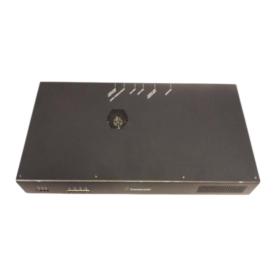
This section demonstrates the manner in which the chassis are arranged on the T2080QDS board. NOTE The Hardware kit contents can be found in attached packing list provided with the board support package. QorIQ T2080 Development System Quick Start Guide, Rev. 0 Freescale Semiconductor... - Page 3 T2080 QDS external view, that includes front and back enclosure of chassis. Figure 1. T2080QDS chassis front view Figure 2. T2080QDS chassis back view Figure 3 shows the open state of T2080QDS chassis: QorIQ T2080 Development System Quick Start Guide, Rev. 0 Freescale Semiconductor...
-
Page 4: T2080Qds Board Drawings
T2080QDS board drawings Figure 3. T2080QDS open state of chassis T2080QDS board drawings In this section: • Section 4.1, “T2080QDS Component Side View” • Section 4.2, “T2080QDS Print Side View” QorIQ T2080 Development System Quick Start Guide, Rev. 0 Freescale Semiconductor... - Page 5 T2080QDS board drawings T2080QDS Component Side View Figure 4. T2080QDS Component Side View QorIQ T2080 Development System Quick Start Guide, Rev. 0 Freescale Semiconductor...
- Page 6 T2080QDS board drawings T2080QDS Print Side View Figure 5. T2080QDS Print Side View QorIQ T2080 Development System Quick Start Guide, Rev. 0 Freescale Semiconductor...
-
Page 7: Switch Default Settings
USB PHY Transceiver 1.8V Supply USB_HVDD1 & 2 USB PHY Transceiver 3.3V Supply SYSCLK (Synthesizer REF System Clock CLK) Platform Clock Depends on RCW DDR CLK (Synthesizer REF Depends on RCW 133.33 CLK) QorIQ T2080 Development System Quick Start Guide, Rev. 0 Freescale Semiconductor... - Page 8 SerDes2 Reference Clock 2 EC1_GTXCLK_125 Eth1 MAC reference clock EC2_GTXCLK_125 Eth2 MAC reference clock USBCLK USB Block reference clock TSEC_1588_CLK_IN PTP block input clock RTC CLK Real-time Clock 3.125 QorIQ T2080 Development System Quick Start Guide, Rev. 0 Freescale Semiconductor...
- Page 9 111 - Reserved SW2.7: RSP_DIS • 1 - Reset Seq. normal [Default] • 0 - Reset Seq. Pause SW2.8: DRAM_TYPE • 0 - DDR3 (1.5V) [Default] • 1 - DDR3L (1.35V) QorIQ T2080 Development System Quick Start Guide, Rev. 0 Freescale Semiconductor...
- Page 10 • 11 - 100.00MHz [Default] (fixed from 871S1022EKLFT) SW4.[7:8] SERDES2 Clock2 • 00 - 100.00 MHz (from 8T49N222A) • 01 - 125.000 MHz • 10 - 156.250 MHz • 11 - 100.00MHz [Default] (fixed from 871S1022EKLFT) QorIQ T2080 Development System Quick Start Guide, Rev. 0 Freescale Semiconductor...
- Page 11 • 01100110 Note: The DIP-SWITCH positions reflect the SerDes Protocol for T2080 SD1. For more details, see Table 19-2, “SerDes Lanes Assignments and Multiplexing” of T2080QDS Reference Manual . QorIQ T2080 Development System Quick Start Guide, Rev. 0 Freescale Semiconductor...
- Page 12 • 10 - 3.3V • 11 - Reserved SW9.7: SPARE7 (LVDD Preset) • Not used [Default] SW9.8: POVDD Enable • 0 - Remains OFF [Default] • 1 - Can be Powered up QorIQ T2080 Development System Quick Start Guide, Rev. 0 Freescale Semiconductor...
- Page 13 • 001 - CCS to QIXIS Only (Use for I2C EEPROM’s programming) • 010 - CCS to QIXIS, then DUT • 011 - Aurora to QIXIS, then DUT • 100 - CCS to QIXIS to DUT to Board 2 QorIQ T2080 Development System Quick Start Guide, Rev. 0 Freescale Semiconductor...
- Page 14 • 1 - Normal Mode [Default] • 0 - Connect CWTAP Header to FPGA for programming SW11.6: SPARE 9 SW11.[7:8] DCM Control • 00 - Reserved; [Default] SW12.[1:8]: SPARE SW12 Configuration QorIQ T2080 Development System Quick Start Guide, Rev. 0 Freescale Semiconductor...
- Page 15 Switch default settings Figure 6 shows the T2080QDS DIP-switch locations. Figure 6. T2080QDS DIP-switch locations QorIQ T2080 Development System Quick Start Guide, Rev. 0 Freescale Semiconductor...
-
Page 16: Connector Default Settings
TSEC_1588 PTP test OPEN QIXIS DISPLAY Header FPGA optional service display connection OPEN PEX SLOT-1 PEX Socket 98-pin OPEN PEX SLOT-2 PEX Socket 98-pin OPEN PEX SLOT-5 PEX Socket 98-pin OPEN QorIQ T2080 Development System Quick Start Guide, Rev. 0 Freescale Semiconductor... - Page 17 2x4-pin Chassis LED and software’s connection ATX-PS 12V2 Connector 2x2-pin External ATX-PS 12V connection Dual RS-232: DB-9 RS-232 2x9-pins External RS-232 adapter cable • UART1/3-Bottom connection OPEN • UART2/4-Top QorIQ T2080 Development System Quick Start Guide, Rev. 0 Freescale Semiconductor...
- Page 18 130NS 2.7-3.6V 1.8V IO TSOP56 + SKT 56 TSOP SMT 0.5MM 210H AU Battery Holder Socket — Standby battery CR2032 inserted Figure 7 shows the connectors locations. T2080QDS connectors Figure 7. QorIQ T2080 Development System Quick Start Guide, Rev. 0 Freescale Semiconductor...
-
Page 19: Jumper Default Settings
• Connected: Enabled VDD_LP_BAT • Disconnected [Default]: Disabled VDD_LP_BAT Header 1x2-pin FORCE ATX-ON • Connected: Force ATX-PS ON • Disconnected [Default]: Normal operation Header 1x2-pin 12V current sense Not assembled resistors bypass QorIQ T2080 Development System Quick Start Guide, Rev. 0 Freescale Semiconductor... - Page 20 Jumper default settings Figure 8 shows the T2080QDS jumper locations. Figure 8. T2080QDS jumper locations QorIQ T2080 Development System Quick Start Guide, Rev. 0 Freescale Semiconductor...
-
Page 21: Push Buttons
Press SW14 to issue processor IRQ (TBD) SW13 Hard Reset Press SW13 for Hard Reset (HRST) Figure 9 shows the push button locations. Figure 9. T2080QDS push button locations QorIQ T2080 Development System Quick Start Guide, Rev. 0 Freescale Semiconductor... -
Page 22: Led Lights
ON: VDD_AUX voltage supply OFF: VDD_AUX voltage supply Yellow ASLEEP Asserted: T2080 HRESET T2080 HRESET unasserted PORESET Asserted: T2080 PORESET T2080 PORESET unasserted RSTREQ Asserted: T2080 RESET REQUEST T2080 RESET REQUEST unasserted QorIQ T2080 Development System Quick Start Guide, Rev. 0 Freescale Semiconductor... - Page 23 • Some/all of on-board voltage is in • All reset configuration and poor condition sequencer passed • Some/all of on-board reset configuration devices fail Green ON: 3.3V voltage supply OFF: 3.3V voltage supply QorIQ T2080 Development System Quick Start Guide, Rev. 0 Freescale Semiconductor...
- Page 24 LED lights Figure 10. T2080QDS LED (D) locations QorIQ T2080 Development System Quick Start Guide, Rev. 0 Freescale Semiconductor...
-
Page 25: Working Environment
The board is marked with several Caution Hot locations (R425, R494, R563, R572, R996, and R1003); they are a consideration when the chip is in ASLEEP mode and no processor is attached on the board. QorIQ T2080 Development System Quick Start Guide, Rev. 0 Freescale Semiconductor... - Page 26 Power the board using the external ATX12V power supply. The LED D34 (HOT_5V) will glow green. b) Move the power switch (SW15) to ON. c) Verify the LEDs D3:D39 complete the Power-ON reset sequence. d) Move the power switch (SW15) to OFF. QorIQ T2080 Development System Quick Start Guide, Rev. 0 Freescale Semiconductor...
- Page 27 Align the red stripe of the USB-UTAP connector cable with Pin 1 of the JTAG/COP 16-pin connector (at J39). b) Connect the connector cable to J39. c) Move the power switch (SW15) to ON. d) Verify the LEDs D3:D39 complete the Power-ON reset sequence. QorIQ T2080 Development System Quick Start Guide, Rev. 0 Freescale Semiconductor...
- Page 28 Connect the shielded cable at P2-Bottom–GETH1,or P2–Top-GETH2. NOTE Only one shielded Ethernet RJ45 cable is included in the T2080QDS kit. d) Connect a USB*A-to-MicroUSB*B cable to J1 -USB2(OTG). QorIQ T2080 Development System Quick Start Guide, Rev. 0 Freescale Semiconductor...
-
Page 29: Serdes Options
2 (J31) PEX1,PEX2: Gen2 x1; SGMII x2x3 3 (J37) PEX3: Gen2 x1x4x8; SGMII x2x4; XAUI-HiGig 4 (J38) PEX1: Gen2 x4 x8, Gen3 x4; SRIO2 5 (J32) PEX2 Gen2 x2x4; SRIO1 QorIQ T2080 Development System Quick Start Guide, Rev. 0 Freescale Semiconductor... - Page 30 Section 11, “Getting started with T2080QDS”. 3. Insert the XAUI riser card into J37 slot. 4. Connect the cable to an external destination. 5. Move the power switch (SW15) to ON. QorIQ T2080 Development System Quick Start Guide, Rev. 0 Freescale Semiconductor...
- Page 31 3. Insert the PEX loopback card into J30, J31, J32, J37, and J38 slots depending on the selected mode. 4. Move the power switch (SW15) to ON. Figure 17. PEX loopback card connections QorIQ T2080 Development System Quick Start Guide, Rev. 0 Freescale Semiconductor...
- Page 32 3. Connect optical cable/cables between SFP modules or to external test system (alternatively connect XFI cable to the external test system). 4. Move the power switch (SW15) to ON. Figure 18. SFP module connections QorIQ T2080 Development System Quick Start Guide, Rev. 0 Freescale Semiconductor...
-
Page 33: Appendix A: Combinations Of Sysclk And Ddrclk
Figure 19 lists the correct combinations of SYSCLK and DDRCLK. The yellow and red markings are measured values different from expected values. Figure 19. Combinations of SYSCLK and DDRCLK QorIQ T2080 Development System Quick Start Guide, Rev. 0 Freescale Semiconductor... -
Page 34: Appendix B: Revision History
Appendix B: Revision history 14 Appendix B: Revision history Table 10 summarizes revisions to this document. Table 10. Revision history Revision Date Description Rev. 0 10/2015 Initial Public release. QorIQ T2080 Development System Quick Start Guide, Rev. 0 Freescale Semiconductor... - Page 35 Appendix B: Revision history QorIQ T2080 Development System Quick Start Guide, Rev. 0 Freescale Semiconductor...
- Page 36 Architecture and Power.org word marks and the Power and Power.org logos and related marks are trademarks and service marks licensed by Power.org. ARM and Cortex are registered trademarks of ARM Limited. ARMnnn is the trademark of ARM Limited. © 2015 Freescale Semiconductor, Inc. Document Number: T2080QDSQS Rev. 0, 926-28012 REV 0...
Need help?
Do you have a question about the QorIQ T2080 and is the answer not in the manual?
Questions and answers