Sign In
Upload
Download
Table of Contents
Contents
Add to my manuals
Delete from my manuals
Share
URL of this page:
HTML Link:
Bookmark this page
Add
Manual will be automatically added to "My Manuals"
Print this page
×
Bookmark added
×
Added to my manuals
Manuals
Brands
GE Manuals
Air Conditioner
AEE07KP
Service manual
GE AEE07KP Service Manual
Window type
Hide thumbs
Also See for AEE07KP
:
Use & care manual
(20 pages)
1
2
3
4
5
6
7
8
9
10
11
12
13
14
15
16
17
18
19
20
21
22
23
24
25
26
27
28
29
30
31
32
33
34
35
36
37
38
39
40
41
42
43
44
45
46
47
48
49
50
51
52
53
54
55
56
57
58
59
60
61
62
63
64
65
66
67
68
69
70
71
72
73
74
Table Of Contents
75
page
of
75
Go
/
75
Contents
Table of Contents
Troubleshooting
Bookmarks
Table of Contents
Table of Contents
Product View
Summary and Features
1 Safety Precautions
2 Specifications
3 Construction Views
4 Refrigerant System Diagram
5 Schematic Diagram
Electrical Wiring
Electrical Data
Printed Circuit Board
6 Function and Control
Remote Control Operations
Cool Mode
Cooling Descriptions
Auto Fan Speed
Power Outage Recovery Feature
Replacement of Batteries
Name and Function of Wireless Remote Control
General Operation
Optional Operation
Introduction for Special Function
About AUTO Mode/About Lock/Switch between Fahrenheit and Centigrade
Changing Batteries
Operation Introduction of Remote Controller
Buttons on Remote Controller
Icon Display on Remote Controller
Simple Operation
Replacement of Batteries in Remote Controller
Remote Control Panel
Description of each Control Operation
Cooling Mode
Dry Mode
Energy Saving Mode/Fan Mode
Swing/Buzzer/Sleep/Auto Wind
Warning Function of Filter
Memory Function
LED, Dual 8 Nixietbe
Temperature Setting
Function Setting for Buttons
Protection Function
Malfunction Detection for Temperature Sensor
System Basis Function
Cooling Mode/Auto Mode
Fan Mode/Dry Mode
Button Function Setting
7 Installation Instructions
Location
Installation of Accessories
Drain Water
Relocation
Noise
Notes on Electrical Wiring
Model AEE07KP Exploded View and Parts List
Models AEE09KP, AEE12KP Exploded View and Parts List
Model AEE18KP Exploded View and Parts List
Model AEE24KP Exploded View and Parts List
Model AED07KP Exploded View and Parts List
Model AED09KP Exploded View and Parts List
Model AED12KP Exploded View and Parts List
9 Troubleshooting
10 Removal Procedure
Appendix
Appendix 1: Reference Sheet of Celsius and Fahrenheit
Appendix 2: List of Resistance for Temperature Sensor
Over
Advertisement
Quick Links
1
Product View
2
Specifications
3
Function and Control
4
Remote Control Operations
5
Cool Mode
6
Description of each Control Operation
7
Troubleshooting
Download this manual
See also:
Use and Care Manual
GE
Appliances
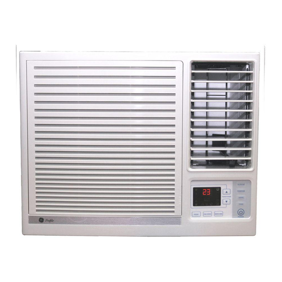
GE Window Type Air Conditioner
AEE07KP, AED07KP,AEE09KP, AED09KP,AEE12KP,
AED12KP,AEE18KP, AEE24KP,
Service Manual
Table of
Contents
Previous
Page
Next
Page
1
2
3
4
5
Advertisement
Table of Contents
Need help?
Do you have a question about the AEE07KP and is the answer not in the manual?
Ask a question
Questions and answers
Related Manuals for GE AEE07KP
Air Conditioner GE AEV07KP Use & Care Manual
Window type (20 pages)
Air Conditioner GE AEE08AK Dimension Manual
115 volt heat/cool room air conditioner (2 pages)
Air Conditioner GE AEE08AK Owner's Manual And Installation Instructions
Ge aee08ak: user guide (52 pages)
Air Conditioner GE AEE08ASL1 Owner's Manual And Installation Instructions
(52 pages)
Air Conditioner GE AEE08 Owner's Manual And Installation Instructions
General electric room air conditioner owner's manual and installation instructions (16 pages)
Air Conditioner GE AEE12DN Owner's Manual And Installation Instructions
Ge aee12dn: user guide (53 pages)
Air Conditioner GE AEE12DQ Owner's Manual & Installation Instructions
Room air conditioner (53 pages)
Air Conditioner GE AEE08 Owner's Manual And Installation Instructions
(52 pages)
Air Conditioner GE AEE12 Owner's Manual And Installation Instructions
(16 pages)
Air Conditioner GE Appliances AEE08 Owner's Manual And Installation Instructions
(52 pages)
Air Conditioner GE AEE08 Owner's Manual And Installation Instructions
(52 pages)
Air Conditioner GE AEE08 Owner's Manual & Installation Instructions
(52 pages)
Air Conditioner GE AEE08 Owner's Manual & Installation Instructions
(52 pages)
Air Conditioner GE AEE12DT Owner's Manual And Installation Instructions
(52 pages)
Air Conditioner GE AEE12DRL1 Owner's Manual And Installation Instructions
(52 pages)
Air Conditioner GE AEE08AP Energy Manual
Without reverse cycle with lowered sides (1 page)
This manual is also suitable for:
Aed07kp
Aee09kp
Aee12kp
Aed12kp
Aee18kp
Aee24kp
...
Show all
Aed09kp
Table of Contents
Print
Rename the bookmark
Delete bookmark?
Delete from my manuals?
Login
Sign In
OR
Sign in with Facebook
Sign in with Google
Upload manual
Upload from disk
Upload from URL


Need help?
Do you have a question about the AEE07KP and is the answer not in the manual?
Questions and answers