Table of Contents
Advertisement
Advertisement
Table of Contents

Related Manuals for CAB MACH2


Summary of Contents for CAB MACH2
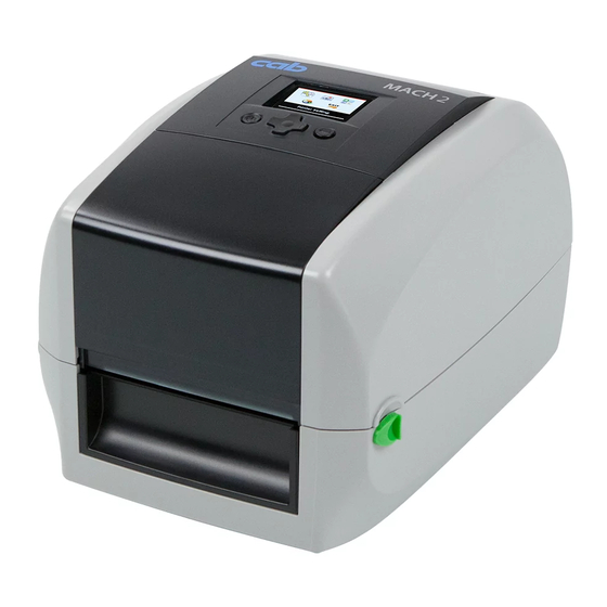
- Page 1 Operator's Manual MACH2 Label Printer Made in Germany...
- Page 2 Please check www.cab.de for the latest update. Terms and conditions Deliveries and performances are effected under the General conditions of sale of cab Produkttechnik GmbH & Co. KG. Germany France Asia cab Produkttechnik cab technologies s.a.r.l.
-
Page 3: Table Of Contents
Table of Contents Introduction ............................4 Instructions ............................... 4 Intended Use ............................4 Safety Instructions ............................ 5 Environment ............................. 5 Device Overview ............................. 6 Unpacking and Box Content ........................6 Device Views ............................7 2.2.1 Front View ............................7 2.2.2 Rear View ............................ -
Page 4: Introduction
Introduction Instructions Important information and instructions in this documentation are designated as follows: Danger! Draws attention to an exceptionally great, imminent danger to your health or life due to hazardous voltages. Danger! Draws attention to a danger with high risk which, if not avoided, may result in death or serious injury. Warning! Draws attention to a danger with medium risk which, if not avoided, may result in death or serious injury. -
Page 5: Safety Instructions
Introduction Safety Instructions The device is configured for voltages of 100 to 240 V AC. It only has to be plugged into a grounded socket. • • Only connect the device to other devices which have a protective low voltage. • Switch off all affected devices (computer, printer, accessories) before connecting or disconnecting. •... -
Page 6: Device Overview
2. Check printer for damage which may have occurred during transport. 3. Set up printer on a level surface. 4. Check delivery for completeness. 1 MACH2 Label Printer 2 Empty ribbon core 3 Ribbon hubs - Set of 2 4 USB cable... -
Page 7: Device Views
Device Overview Device Views 2.2.1 Front View 1 Printer cover 2 Operation panel 3 Cover of ribbon rewind mechanism 4 Front cover 5 Cover release catches 6 LCD Display 7 Navigator Pad 8 FEED Button 9 POWER Button Fig. 2 Front View 2.2.2 Rear View... -
Page 8: Bottom View
Device Overview 2.2.3 Bottom View 16 Cover of the module connection jacks Fig. 4 Bottom View Note! The cut-outs at the device bottom are not intended for wall-mount use. 2.2.4 The Internal View of Printer 1 Label guide plate 2 Label supply hub 3 Release catch for opening the label supply hub 4 Label Guide... -
Page 9: The Printing Mechanism
Device Overview 2.2.5 The Printing Mechanism 1 Cover for ribbon rewind mechanism 2 Ribbon rewind wheel 3 Notch of ribbon rewind wheel 4 Ribbon supply wheel 5 Notch of ribbon supply wheel 6 Paper press bar 7 Print head Fig. 6 Printing Mechanism... -
Page 10: Connecting And Switching On The Device
Connecting and Switching on the Device Connecting the Printer Attention! Risk of damage to devices! Inadequate or no grounding can damage devices and cause malfunctions during operation. Ensure that all computers and cables connected to the printer are grounded. Note! The printer is equipped with a wide area power unit. -
Page 11: Connecting To A Computer
Connecting and Switching on the Device 3.1.2 Connecting to a Computer Attention! Loss of material! The RS-232 interface is unsuitable for fast transmission of changing data. Use USB or Ethernet interface for print operation. Use the RS-232 interface only for setting up the printer. Fig. -
Page 12: Loading Material
Loading Material Open the Printer Fig. 10 Open the Printer 1. Place the printer on a flat surface. 2. Pull the cover release catches (1) on both sides of the printer. 3. Raise the cover of the casing (2) and lock it into the catch. Note! The printing mechanism is lifted up with the printer cover. -
Page 13: Ribbon Supply Module
Loading Material 4.2.2 Ribbon Supply Module 放入 Fig. 12 Loading the ribbon module on the ribbon supply wheel 1. Unroll about 30 cm of the ribbon (1) from the roll, and place it as shown in the illustration. 2. Insert the ribbon hub and the ribbon roll (2) into the left side (3) of the ribbon supply module. Ensure that the stud on the ribbon hub slots into the recess. -
Page 14: Ribbon Rewind Module
Loading Material 4.2.3 Ribbon Rewind Module Fig. 14 Loading the ribbon module on the ribbon rewind wheel 1. Open the cover for Ribbon rewind mechanism (1). 2. Insert the ribbon hub with the ribbon core (2) into the left side (3) of the ribbon rewind module. Ensure that the stud on the ribbon hub slots into the recess. -
Page 15: Loading / Replacing The Label Stock On The Printer
Loading Material Loading / Replacing the Label Stock on the Printer 1. Open the printer 4.1 on page 12. Fig. 16 Loading the label stock Note! The side label guide plates (2) can be shifted as long as the locking button (1) remains pressed. 2. -
Page 16: Function Test
Loading Material Function Test Fig. 18 Function Test 1. Connect the printer to the power supply. 2. Switch the printer on. 3. Press the FEED button (1). If the label stock is inserted correctly, the labels are drawn in straight. Note! If the labels are drawn in skewed, check the seating of the ribbon and the label stock, and correct if necessary. -
Page 17: Installing Software And Configurate The Printer
Installing Software and Configuring the Printer Installing the Printer Driver Note! When the printer is conneted via USB cable, the driver installation will be automatically made. Insert the product DVD into the DVD drive of your computer, and enter this drive when you are prompted to enter a source for the driver during the installation. -
Page 18: Installing Labeling Software Cablabel S3 Lite
Installing Software and Configuring the Printer Installing Labeling Software cablabel S3 Lite Note! To create your labels, you can use the software cablabel S3 Lite. This label design software is included on the product CD and is free of charge. You can obtain further software solutions with an extended range of functions (e.g. cablabel S3 Pro) from the manufacturer. -
Page 19: Configuration Of Printer Settings
Installing Software and Configuring the Printer Configuration of Printer Settings The Software Tool Mach1/2-Load Note! The software tool Mach1/2-Load is used to manage the printer settings and the configuration of the interfaces. Starting the Tool Mach1/2-Load Insert the Product DVD in the DVD drive of the host computer. Start the Tool Mach1/2-Load by a double click Printer Configuration This tab allows you to configure and edit the settings of the connected printer. Almost all important settings of the printer can be configured here. Click "GET" to load the settings from the printer, ... - Page 20 Installing Software and Configuring the Printer Printer I/O Setup On this tab, you can make settings for the possible interfaces and send them to the printer. Port opens the "Port Setting". Here you have the possibility to search for all Mach1/2 models.
-
Page 21: Printer Setting And Control
Printer Setting and Control Operation Panel Operation Panel Overview 1 POWER Button 2 FEED Button 3 LCD Display 4 Navigator Pad Fig. 19 Operation Panel Overview POWER button Press the POWER button (1) to turn on the printer, and the START UP SCREEN appears. The printer is on “ready to print”... -
Page 22: Lcd Interface - Introduction
When printer is on standby status (ready to print), the LCD interface will display “Ready” on screen. You can only print on this “Ready“ status. MACH2/200 V1.RC0 If there is any printers error, the LCD screen will display the error screen to show the type of error. - Page 23 1.008 - 160428 If the printer is on “ready to print” status, the LCD screen should display the message “Ready“ on the screen. MACH2/200 V1.RC0 Please keep pressing „ button and wait for the timer to be filled, then the LCD interface will enter into the MAIN PAGE for SETTING MODE. You can make various setting functions in SETTING MODE.
- Page 24 Printer Setting and Control Operations on Setting Page On MAIN PAGE, press „ or ƒ button to move the cursor and select the functions. Select a designated function and press FEED button, you will enter the SETTING PAGES for the function. Select Enter On SETTING PAGES, press „...
- Page 25 Printer Setting and Control On SETTING VALUE PAGES, press or ‚ dbutton to change the setting values. Select Press FEED button will apply the setting value you just selected, and the red tick will appear to mark the value. Apply Note! The blue arrow indicates the value you are selected.
- Page 26 Printer Setting and Control Exit from Current Page to Ready Status The icon on top-left corner displays the capture of upper level screen and also guides you back to upper level with left or up arrow. NAVIGATION ICON On SETTING VALUE PAGES, press ƒ button will go back to the upper level screen. Back to the Setting page On SETTING PAGES, press ...
- Page 27 Printer Setting and Control On MAIN PAGE select Symbol EXIT and press the FEED button. The printer now displays again the status "Ready". EXIT from Setting Mode MACH2/200 V1.RC0 Back to the Ready status...
-
Page 28: Ethernet Setting
Printer Setting and Control Ethernet Setting Operations on Setting Page On MAIN PAGE press „ or ƒ button to move the cursor and select the functions. Select a designated function and press FEED button, you will enter the SETTING PAGES for the function. Select Device Device Enter Ethernet Setting... - Page 29 Printer Setting and Control The default of DHCP is Disable. Press or ‚ button to change the setting values. Ethernet Ethernet Select to enable DHCP Press FEED button twice to save the setting. Ethernet Press FEED once to exit. Press FEED again to save and return to previous SETTING PAGE.
-
Page 30: Lcd Password
Printer Setting and Control LCD Password Operations on Setting Page On MAIN PAGE, press „ or ƒ button to move the cursor and select the functions. Seclect a designated function and press FEED button, you will enter the SETTING PAGE for the function. Select Device Enter LCD Password... - Page 31 Printer Setting and Control PIN protection Select button again to setup the password Press FEED button twice to svae the setting. PIN protection Press FEED button onece to exit. Press FEED button again to save and reture to previous SETTING PAGE...
-
Page 32: Lcd Interface - Function
Printer Setting and Control LCD Interface – Function Main Page Setting items for printer, ex. Printing speed, heat level. Also includes a Printing Wizard for your ease of printing. Printer Setting Setting items for printing label, ex. Rotation, Printing position offset. Label Setting Option modules and connection port settings. - Page 33 Printer Setting and Control Setting Items in Setting Mode English Español 日本語 Deutsch 繁體中文 Language Italiano Printer Setting Pусский 简体中文 Français Türkçe Print speed 2-5 or 7 Heat level 0-19 Label with Gaps Media Type Label with Marks Wizard Continuous Direct Thermal Print Mode Thermal Transfer...
- Page 34 Printer Setting and Control Key tone Enter Abbrechen None Present Sensor Options Device Setting Cutter Applicator Device Smart Backfeed Apply Cancel Part. 09100 Disable DHCP Enable Ethernet Gateway 192.168.000.254 Dynamic IP 192.168.102.76 Netmask 255.255.255.0 Disable LCD Password Enable 4800 bps 38400 bps Baud Rate 9600 bps...
-
Page 35: Label Calibration And Self Test
Printer Setting and Control Label Calibration and Self Test Label Calibration The printer can automatically detect and store label height. That means the host computer does not need to transmit the label height to the printer. Self Test Self-test function lets you check whether the printer is functioning normally. Here is how you run the label size calibration and self test. - Page 36 Printer Setting and Control Label Calibration Button Note! A hardware button to make a Label Calibration while printer encountering ‘’Media Error’’ during the cases when first-time printer start up or change label or ribbon to another type, such as change using gap label to continuous or black mark labels. Press C-button for 2 seconds, it will make an auto-sensing to calibrate the label and ribbon’s parameters. Fig.
-
Page 37: Maintenance
Maintenance Note! The printer does not require any maintenance. Apart from consumables (ribbon / label stock), no mechanical components have to be set up or changed in order to operate the device. Cleaning 7.1.1 General Cleaning Information Danger! Risk of death via electric shock! ... -
Page 38: Error Alerts
In the event of a problem that prevents normal functioning of the printer, you will see an error message on LCD screen and hear some beep signals. Status Type Beeps Description Solution MACH2/200 V1.RC0 Print 2 x 4 The printing mechanism is Head Open the print mechanism and close it again. beeps notcorrectly closed. -
Page 39: Troubleshooting
Maintenance A file of the same name MACH2/200 V1.RC0 Change the name of the file and try storing it 2 x 2 already exists. The printer File Error beeps prints the message again. "Duplicate Name". Table 4 Error Alerts Troubleshooting Problem Lösung Please make sure that the label stock is loaded the right way up and that it is suitable material. -
Page 40: Accessories
Accessories Preparation Steps Note! The accessories, Present Sensor and cutter, can only be installed separately. They cannot be combined. Open the Printer Fig. 22 Open the printer Place the printer on a flat surface. Pull the cover release catches (1) on both sides of the printer. ... - Page 41 Accessories Remove the platen Fig. 24 Remove the platen Lift up the release clips (4) on both sides of the platen (5). Pull upward the platen (5). Note! Load the ribbon and the label. For further information 4 on page 12.
-
Page 42: Installing The Present Sensor
Accessories Installing the Present Sensor Note! A label liner thickness of 0.006 mm ± 10% and a weight of 65 g/m2 ± 6% are recommended. The Present Sensor will take labels up to a max. width of 118 mm. When using the Present Sensor, set the stop position (printer command ^E) to 13. The Overview of the Label Dispenser 1 Paper sensor 2 Paper feed roller... - Page 43 Accessories Fig. 27 Place the platen 5. Place the platen (6) back to the printer. 6. Lock the platen (6) with the clips (7) on both sides. Fig. 28 Closing the and turning printer 7. Release catch for closing the printer cover (8) and close the printer. 8.
- Page 44 Accessories Fig. 30 Plug the connector 10. Plug the connector (3) fo the Present Sensor to the lower jack (A). Note! There are 2 jacks : the lower jack (A) for the Present Sensor, the upper jack (B) for the cutter. 11.
- Page 45 Accessories 1, 4 Fig. 32 Feeding path of label and liner 6. Push the label liner (11) forwards until it appears at the underside of the Present Sensor. 7. Detach two test labels (10), and feed them over the cover (4) with the paper sensor (1). Fig.
- Page 46 Accessories Function Test 1. Switch the printer on. 2. Press the FEED button (15). 3. Label is transported forwards and detached from the backing material. 10 11 Fig. 34 Function of Present Sensor Note! The label (10) will be peeled from the liner (11) while it passes through the Present Sensor. There is a paper sensor on the Present Sensor module.
-
Page 47: Installing The Cutter
Accessories Installing the Cutter Note! Do not use to cut adhesive labels! Glue residue will be left on the cutter blade and impair its functioning. You can cut paper with a max. width of 116 mm. Labels should be at least 30 mm high. We advise against using inside wound label stock. - Page 48 Accessories Fig. 37 Place the platen 4. Place the platen (5) back to the printer. 5. Lock the platen (5) with the clips (6) on both sides. Fig. 38 Closing the and turning printer 6. Release catch for closing the printer cover (7) and close the printer. 7.
- Page 49 Accessories Fig. 40 Plug the connector 9. Plug the connector (3) fo the Cutter to the upper jack (B). Note! There are 2 jacks : the lower jack (A) for the Present Sensor, the upper jack (B) for the cutter. 10.
- Page 50 Accessories Function Test 1. Switch the printer on. 2. Press the FEED button (11) to set the label position. 3. Label is transported forwards and cut. Fig. 42 Function test of the cutter...
-
Page 51: Appendix
Appendix Technical Data Label Printer MACH2/200 MACH2/300 Print Head Printing method Thermal transfer, direct thermal Printable resolution Print speed up to mm/s Print width up to mm 105,7 Material Paper, cardboard, plastics ■ continuous material on a roll or fanfold... - Page 52 Appendix Label Printer MACH2/200 MACH2/300 Operation panel ■ Buttons Feed ■ On/Off ■ Material sensor calibration LEDs Ready Status ■ Colored TFT display with navigator pad On Display Printer settings Analysis Label settings Finish Accessories Digital clock Control End of ribbon...
-
Page 53: Interface
Server 2012 R2 Table 6 Technical Data ■ Standard □ Option All information on the design and technical specifications correspond to the date of the printing. Subject to change. For current data see website www.cab.de/labelprinter. Limitations may apply to small labels, thin materials or strong adhesives. These applications need to be tested and approved. Interface Pinout Description • Connector Type: Type B Pin No. -
Page 54: Reference To The Eu Declaration Of Conformity
Directive 2011/65/EU on the restriction of the use of certain hazardous substances in electrical and electronic equipment EU Declaration of Conformity https://www.cab.de/media/pushfile.cfm?file=2836 NOTE : This equipment has been tested and found to comply with the limits for a Class A digital device, pursuant to Part 15 of the FCC Rules. -
Page 55: Index
Index Accessories ........40 Operation Panel......21, 52 Overview..........6 Box Content ........6 Platen ......41, 43, 48 POWER Button....7, 11, 21 cablabel S3 ........18 Power cord .........6 Cleaning ...........37 Power plug........10 Configuration ........19 Power Supply ......10, 51 Cutter ........40, 47 Present Sensor ......40, 42 Printer Driver ........17 Print Head.........37, 51 Environment ........5...
Need help?
Do you have a question about the MACH2 and is the answer not in the manual?
Questions and answers