Table of Contents
Advertisement
Quick Links
Advertisement
Table of Contents

Related Manuals for CAB Hermes C Series


Summary of Contents for CAB Hermes C Series
- Page 1 Operator's Manual Hermes C Label Printer Made in Germany...
- Page 2 Edition: 03/2018 - Part No. 9009754 Copyright This documentation as well as translation hereof are property of cab Produkttechnik GmbH & Co. KG. The replication, conversion, duplication or divulgement of the whole manual or parts of it for other intentions than its original intended purpose demand the previous written authorization by cab.
-
Page 3: Table Of Contents
Table of Contents Introduction ............................4 Instructions ............................... 4 Intended Use ............................4 Safety Instructions ............................ 5 Safety Marking ............................6 Environment ............................. 6 Installation .............................. 7 Device Overview ............................7 Unpacking and Setting-up the Printer ...................... 9 Connecting the Device ........................... 10 Switching on the Device ......................... -
Page 4: Introduction
The printer is designed for the integration into a production line. It is intended exclusively for printing suitable materials that have been approved by the manufacturer and for coupling a cab or non-cab applicator which transfers labels from the printer to a product. Any other use or use going beyond this shall be regarded as improper use. -
Page 5: Safety Instructions
Introduction Safety Instructions The device is configured for voltages of 100 to 240 V AC. It only has to be plugged into a grounded socket. • • Only connect the device to other devices which have a protective low voltage. •... -
Page 6: Safety Marking
Introduction Safety Marking Figure 1 Safety marking Danger spot ! • Risk of burning on the hot printhead assembly (1). Do not touch the printhead during operation, and allow to cool down before changing material and before disassembly. • Entanglement hazard by turning roller (2). -
Page 7: Installation
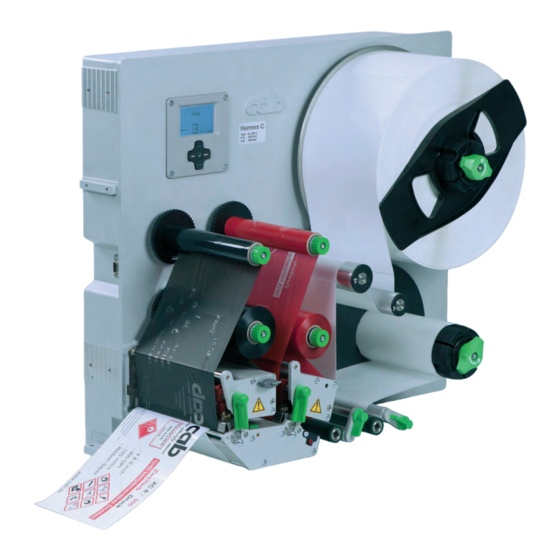
Device Overview 1 Cover (Option) 2 Control panel 3 Ribbon take-up hub AC 4 Ribbon take-up hub MC 5 Interface for cab-applicators 6 Ribbon supply hub AC 7 Ribbon supply hub MC 8 Print mechanism 9 Cover (Option) 10 Roll retainer... - Page 8 Installation 32 Power switch 33 Power connection jack 34 Slot for PC Card Type II or WLAN card 35 Slot for CompactFlash memory card 36 Ethernet 10/100 Base-T 37 2 USB master ports for keyboard, scanner or service key 38 USB high-speed slave port 39 Serial RS-232 C port 40 Connector central compressed air valve 41 I/O interface...
-
Page 9: Unpacking And Setting-Up The Printer
Installation Unpacking and Setting-up the Printer Lift the printer out of the box. Check printer for damage which may have occurred during transport. Remove foam transportation safeguards near the printhead. Check delivery for completeness. Contents of delivery: •... -
Page 10: Connecting The Device
Installation Connecting the Device The standard available interfaces and connectors are shown in Figure 4 on page 8. 2.3.1 Connecting to the Power Supply The printer is equipped with a wide area power unit. The device can be operated with a supply voltage of 230 V~/50 Hz or 115 V~/60 Hz without adjustment. -
Page 11: Control Panel
Control Panel Structure of the Control Panel The user can control the operation of the printer with the control panel, for example: • Issuing, interrupting, continuing and canceling print jobs, Setting printing parameters, e.g. heat level of the printhead, print speed, interface configuration, language and •... -
Page 12: Printer States
Control Panel Printer States State Display Description Ready The printer is in the ready state and can receive Ready and configured symbol displays, data. such as time and date Printing label The printer is currently processing an active print Printing label job. -
Page 13: Key Functions
Control Panel Key Functions The key functions depend on the current printer state: - Active functions: Labels and symbols on the navigator pad keys light up. - Active functions light up white in print mode (e. g. menu or feed). - Active functions light up orange in the offline menu (arrows, key 8 ). -
Page 14: Loading Material
Loading Material Note! For adjustments and simple installation work, use the accompanying Allen key located in the print unit. No other tools are required for the work described here. Loading Labels 4.1.1 Positioning the Media Roll on the Roll Retainer Figure 6 Loading label roll 1. - Page 15 Loading Material 4.1.2 Inserting the Labels into the Print Mechanism Figure 7 Inserting the labels into the print mechanism 1. Turn the levers (2,5) counterclockwise to lift the printheads (1,4). 1. Turn the lever (13) clockwise to lift the pinch roller (12) from the backfeed roller (11). 2.
- Page 16 Loading Material 4.1.3 Setting the Label Sensor Figure 9 Setting the Label Sensor The label sensor (4) can be shifted perpendicular to the direction of paper flow for adaptation to the label medium. The sensor unit of the label sensor is visible from the front through the print unit. ...
- Page 17 Loading Material 4.1.4 Guiding the Liner to the Internal Rewinder Figure 10 Guiding the liner to the internal rewinder 1. Turn lever (7) clockwise to lift the locking system (6) from the transport roller (5). 2. Hold rewinder (1) firmly and turn knob (4) clockwise until it stops. 3.
-
Page 18: Setting The Head Locking Systems
Loading Material Setting the Head Locking Systems The printheads are pushed on via two plungers. The locations of the outer plungers must be set to the width of the label medium used so as to • achieve even print quality across the entire label width •... -
Page 19: Loading Transfer Ribbon
Loading Material Loading Transfer Ribbon Figure 12 Loading transfer ribbon Figure 13 Transfer ribbon feed path Attention! Risk of errors by wrong color assignment. Ensure that programming and assignment of ribbon colors to the print units are matching. Use the print unit near the peel-off edge (7) for the main color (typically black) and the other one for the additional color. -
Page 20: Setting The Feed Path Of The Transfer Ribbon
Loading Material Setting the Feed Path of the Transfer Ribbon Transfer ribbon wrinkling can lead to print image errors. Transfer ribbon deflections (3) can be adjusted so as to prevent wrinkles. Note! A maladjustment of the head locking systems may also cause ribbon wrinkling. ... -
Page 21: Printing Operation
Note! The print of a label must be started by the external START or WDR signal ( Interface Description). When operating Hermes+ without cab applicator the removal of the label must be confirmed by the ETE signal ( Interface Description). -
Page 22: Avoiding Loss Of Data
Printing Operation Avoiding Loss of Data Attention! Loss of data! The print images for the two colors of one label are printed at two different places in the media feed. When correctable errors occur labels which are already printed by the printhead for the additional color but not are completed by the printhead for the main color cannot be repeated after error correction. -
Page 23: Cleaning
Cleaning Cleaning Information Danger! Risk of death via electric shock! Disconnect the printer from the power supply before performing any maintenance work. The printer requires very little maintenance. It is important to clean the thermal printheads regularly. This guarantees a consistently good printed image and plays a major part in preventing premature wear of the printhead. -
Page 24: Fault Correction
Fault Correction Types of Errors The diagnostic system indicates on the screen if an error has occurred. The printer is set into one of the three possible error states according to the type of error. State Display Remark pause flashes ... -
Page 25: Problem Solution
Fault Correction Problem Solution Problem Cause Remedy Transfer ribbon creases Head locking system not adjusted Adjust the head locking system. 4.2 on page 18 Transfer ribbon deflection not adjusted Adjust the transfer ribbon deflection. 4.4 on page 20 Transfer ribbon too wide Use a transfer ribbon slightly wider than the width of label. -
Page 26: Error Messages And Fault Correction
Fault Correction Error Messages and Fault Correction Error message Cause Remedy ADC malfunction Hardware error Switch the printer off and then on. If error recurs call service. Barcode error Invalid barcode content, e.g. alphanumeric Correct the barcode content. characters in a numerical barcode Barcode too big The barcode is too big for the allocated Reduce the size of the barcode or move it. - Page 27 Fault Correction Error message Cause Remedy No record found Refers to the optional memory card; Check programming and card contents. database access error The printer is configured for SMTP, but Switch off SMTP in the configuration. No SMTP server there is no SMTP server, or the SMTP Caution! Then a warning cannot be sent by server is not currently available.
-
Page 28: Labels
Labels Label Dimensions Figure 15 Label dimensions Dim. Designation Dim. in mm Label width 46 - 176 Label height 20 - 350 Label distance > 2 Width of liner 50 -180 ≥ 0 Left margin ≥ 0 Right margin Label thickness 0,025 - 0,20 Liner thickness 0,03 - 0,1... -
Page 29: Device Dimensions
Labels Device Dimensions Gap sensor & Reflective sensor Printhead Additional color Printhead Main color Peel-off edge Figure 16 Device dimensions Dim. Designation Dim. in mm Distance printhead main color - peel-off edge 17,5 Distance 1st heating point - material edge Print width 162,6 Distance gap/reflective sensor - material edge... -
Page 30: Licences
Person authorised to compile the technical file : Erwin Fascher Am Unterwege 18/20 99610 Sömmerda Signed for, and on behalf of the Manufacturer : Sömmerda, 05.10.2017 cab Produkttechnik Sömmerda Gesellschaft für Computer- und Automationsbausteine mbH Erwin Fascher 99610 Sömmerda Managing Director... -
Page 31: Eu Declaration Of Conformity
Directive 2011/65/EU on the restriction of the use of certain • EN 50581:2012 hazardous substances in electrical and electronic equipment Signed for, and on behalf of the Manufacturer : Sömmerda, 05.10.2017 cab Produkttechnik Sömmerda Gesellschaft für Computer- und Automationsbausteine mbH Erwin Fascher 99610 Sömmerda Managing Director NOTE : This equipment has been tested and found to comply with the limits for a Class A digital device, pursuant to Part 15 of the FCC Rules. -
Page 32: Index
Index Loading transfer ribbon.....19 Loss of data ........22 Cleaning Printhead ........23 Print roller ........23 Navigator pad ........11 Cleaning Information ......23 Connecting ........10 Contents of delivery ......9 Offline menu ........13 Control panel ........11 Correctable error ......12 Pause ..........12 Critical error ........12 Pause on media low ......22 Peel-off mode ........21 Declaration of conformity ....31...
Need help?
Do you have a question about the Hermes C Series and is the answer not in the manual?
Questions and answers