Table of Contents
Advertisement
Quick Links
Advertisement
Table of Contents

Related Manuals for Pepperl+Fuchs WCS-PG310


Summary of Contents for Pepperl+Fuchs WCS-PG310
- Page 1 FACTORY AUTOMATION MANUAL WCS-PG310 WCS PROFIBUS DP Interface Module...
- Page 2 WCS-PG310 With regard to the supply of products, the current issue of the following document is ap- plicable: The General Terms of Delivery for Products and Services of the Electrical Indus- try, published by the Central Association of the Electrical Industry (Zentralverband Elektrotechnik und Elektroindustrie (ZVEI) e.V.) in its most recent version as well as the...
-
Page 3: Table Of Contents
Dismounting ..................14 Commissioning................. 15 Introduction ..................15 Connecting the WCS Reader ............16 Connecting the WCS-PG310 to the Network ........16 Integrating WCS-PG310 into the PROFIBUS System...... 17 Data Format for Modules ..............23 Appendix ................... 25 Cable Routing in the RS-485 Bus ............. 25... -
Page 4: Introduction
WCS-PG310 Introduction Introduction Content of this Document This document contains information required to use the product in the relevant phases of the product life cycle. This may include information on the following: Product identification Delivery, transport, and storage Mounting and installation... -
Page 5: Symbols Used
WCS-PG310 Introduction Symbols Used This document contains symbols for the identification of warning messages and of informative messages. Warning Messages You will find warning messages, whenever dangers may arise from your actions. It is mandatory that you observe these warning messages for your personal safety and in order to avoid property damage. -
Page 6: Product Description
Product Description Use and Application The WCS-PG310 acts as an interface between the WCS reader and the PROFIBUS DP input card of the control panel. The data is transferred between the WCS reader(s) and the WCS- PG310 via the RS-485 interface, and from the WCS-PG310 to the control panel via the PROFIBUS DP protocol. -
Page 7: Design Of The Device
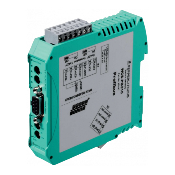
WCS-PG310 Product Description Design of the Device Device components Figure 2.2 Interface module overview Slide switch for RS-485 terminator X1: RS-485 interface Mounting bracket X2: Connection for power supply PROFIBUS communication interface Slide switch for PROFIBUS DP terminator Front panel with rotary coding switches and indicator lights... - Page 8 State Figure 2.3 Front panel overview Power: The "Power" LED is green: The WCS-PG310 interface module is correctly connected to the power supply. State: The "State" LED is green: Data is being exchanged with the WCS readers. The four "ErrorNo/Select ID" LEDs are used to display the number of the currently polled reader.
- Page 9 WCS-PG310 Product Description ErrorNo/Select ID LED Error number Error description LED8 LED4 LED2 LED1 Script error Reserved WCS reader communication, RS send buffer overflow WCS reader communication, RS receive buffer overflow WCS reader communication, RS timeout General fieldbus error Parity error or frame check error...
-
Page 10: Installation
WCS-PG310 Installation Installation Mounting Mounting the modules The module is fastened to a DIN mounting rail with a width of 35 mm using a snap-on fixing method. Figure 3.1 Mounting 1. Hook the module (1) into the DIN mounting rail (2) from above and press it down until it snaps into place. -
Page 11: Electrical Connection
WCS-PG310 Installation Electrical Connection Danger! Device damage due to incorrect installation Faulty installation of cables and connection lines can endanger the function and the electrical safety of the device. Note the permissible core cross section of the conductor. If you are using stranded conductors, crimp the stranded conductors with wire end ferrules. - Page 12 WCS-PG310 Installation Connecting the power supply Connect the operating voltage (10 VDC...30 VDC) to terminals 1 and 2 of the 4-pin plug X2 on the interface module. In addition, note the label on the module. The "Power" LED lights up green.
- Page 13 WCS-PG310 Installation Note! RS-485 bus termination If the interface module is operated as the first or last physical device in an RS-485 bus, there must be a bus termination on this module. To do this, set the "Rx 422 Termination" slide switch to "Off"...
-
Page 14: Dismounting
WCS-PG310 Installation Dismounting Dismounting the modules Use a suitable slot-head screwdriver for dismounting the module. 1. Disconnect all the supply and signal lines. Figure 3.3 Dismounting 2. Insert the screwdriver (2) into the groove of the mounting bracket (3). 3. Press the screwdriver (2) in the specified direction until the lock on the DIN mounting rail (4) opens, see figure. -
Page 15: Commissioning
Components To commission the module, you will require the following components: WCS-PG310 interface module Connection cable from the interface module to the reader Connector for the PROFIBUS connection to the interface module PROFIBUS cable (this cable is usually already installed on site) 10 VDC...33 VDC power supply... -
Page 16: Connecting The Wcs Reader
Table 4.1 Connecting the WCS reader(s) Connecting the WCS-PG310 to the Network A 9-pin connector is used to connect to the PROFIBUS DP, in accordance with the PROFIBUS standard. You therefore need a 9-pin D-sub connector that you can plug into the 9-pin D-sub socket on the device. -
Page 17: Integrating Wcs-Pg310 Into The Profibus System
7. If the rotary switch is set to a value between 0 and 125, the gateway uses this PROFIBUS ID and it is not possible to change the setting via a master. Integrating WCS-PG310 into the PROFIBUS System Warning! Risk of injury due to incorrect configuration An error during the configuration of the device can override the fail-safe function, causing a danger to people and machinery. - Page 18 WCS-PG310 Commissioning Installing the GSD file Figure 4.1 GSD file manage 1. In the menu bar, click the "Options" button and select the function "Install device description file (GSD)." The "Install device description file" window opens. Figure 4.2 Search GSD file 2.
- Page 19 WCS-PG310 Commissioning Figure 4.3 Install GSD file 4. Select the GSD file to install by checking the box (1) to the left of the filename. 5. Click the "Install" button (2). The installation process may take a few minutes. Once the file is installed successfully, the system issues a notification that the installation...
- Page 20 1. Open the hardware catalog and browse through the tree structure until you see the icon la- beled "276147" (1) (Other field devices > PROFIBUS DP > Gateways > PEPPERL+FUCHS > Pepperl+Fuchs > WCS > WCS-PG310 > Header module > 276147).
- Page 21 WCS-PG310 Commissioning Figure 4.5 Integrating gsd file 2. Select module "276147" (1) from the hardware catalog and drag this module into the network view (2). The selected module is displayed in the network view window (2). 3. Connect the module to the control panel. To do this, move the mouse onto the PROFIBUS interface that is highlighted in purple on the control panel, click the left mouse button, and drag the line shown to the PROFIBUS interface on the module.
- Page 22 WCS-PG310 Commissioning Figure 4.6 Device view 1. Switch to the "Device view" tab (1) in the "Devices & Networks" window. 2. Double-click to select the module with the appropriate number of readers and operating mode from the hardware catalog (2).
-
Page 23: Data Format For Modules
WCS-PG310 Commissioning Figure 4.7 Network view 3. Switch to the "Network View" tab (1) in the "Devices & Networks" window. 4. To change the input and output address for the module, double-click on the module (2) in the hardware catalog. - Page 24 WCS-PG310 Commissioning Byte 0 Byte 1 Byte 2 Byte 3 Byte 4 Byte 5 Table 4.4 Data format for each connected WCS reader in "Position and Speed" operating mode, reader address = 0...3 Pxx: position data, P00 = LSB Sxx: speed (in multiples of 0.1 m/s), S00 = LSB Example: Byte 5 = 00011011 = 27, corresponds to 2.7 m/s...
-
Page 25: Appendix
WCS-PG310 Appendix Appendix Cable Routing in the RS-485 Bus The data cables must always form an in-line connection between the first and the last node. This in-line connection must end with a terminator. The RS-485 terminators are integrated in the WCS readers and can be switched on and off with the interface module. - Page 26 WCS-PG310 Appendix Reading head Reading head Interface or control (PLC) Figure 5.2 Connection of two reading heads, Version A Version B: The interface module is located at the beginning of the data line; one WCS reader is located at the end of the data line. Both need the RS-485 terminator. The second WCS reader is connected to the line connection between the interface module and the first WCS reader through a short spur (length <1 m).
- Page 27 WCS-PG310 Appendix Reading head Spur line (max. 1 m) Reading head Interface or control (PLC) Figure 5.3 Connection of two reading heads, Version B The wiring version used depends on which is best suited for the application. If three or four WCS readers are used on the same interface module, connect these using spurs as shown in variant B.
-
Page 28: Data Cables And Accessories
WCS-PG310 Appendix Data Cables and Accessories RS-485 data cable For the RS-485 data transfer path, a four-wire, shielded, twisted pair data cable must be used. One wire pair is used for the supply voltage, and one pair for the RS-485 data connection. The maximum length of the cable depends on the data transfer capacity of the data cable—core-... - Page 29 WCS-PG310 Appendix Single-ended female cordsets and adapter cables Field-attachable female connectors M12 x 1 Number of poles Cable diameter Order designation straight 6 mm – 8 mm V1-G-PG9 angled 6 mm – 8 mm V1-W-PG9 straight 6 mm – 8 mm...
- Page 30 Twinsburg, Ohio 44087 · USA Tel. +1 330 4253555 E-mail: sales@us.pepperl-fuchs.com Asia Pacific Headquarters Pepperl+Fuchs Pte Ltd. Company Registration No. 199003130E Singapore 139942 Tel. +65 67799091 E-mail: sales@sg.pepperl-fuchs.com www.pepperl-fuchs.com Subject to modifications / TDOCT5979__ENG Copyright PEPPERL+FUCHS • Printed in Germany 03/2018...
Need help?
Do you have a question about the WCS-PG310 and is the answer not in the manual?
Questions and answers