Sign In
Upload
Manuals
Brands
WAGO Manuals
I/O Systems
750-464/020-000
WAGO 750-464/020-000 Manuals
Manuals and User Guides for WAGO 750-464/020-000. We have
1
WAGO 750-464/020-000 manual available for free PDF download: Manual
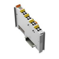
WAGO 750-464/020-000 Manual (118 pages)
WAGO-I/O-SYSTEM 750. 2/4 AI RTD configurable. 2-/4-Channel Analog Input Module for RTDs
Brand:
WAGO
| Category:
I/O Systems
| Size: 2.93 MB
Table of Contents
Table of Contents
3
1 Notes about this Documentation
7
Validity of this Documentation
7
Copyright
7
Table 1: Variants
7
Symbols
8
Number Notation
10
Font Conventions
10
Table 2: Number Notation
10
Table 3: Font Conventions
10
2 Important Notes
11
Legal Bases
11
Subject to Changes
11
Personnel Qualifications
11
Use of the 750 Series in Compliance with Underlying Provisions
11
Technical Condition of Specified Devices
12
Safety Advice (Precautions)
13
3 Device Description
15
View
16
Figure 1: View
16
Table 4: Caption Acc. to Figure "View
16
Connectors
17
Data Contacts/Internal Bus
17
Figure 2: Data Contacts
17
Power Jumper Contacts/Field Supply
18
Figure 3: Power Jumper Contacts
18
Table 5: Power Jumper Contacts
18
Cage Clamp
19
Connectors
19
Connections 4-Channel, 2-Wire
19
Connections 2-Channel, 3-Wire
19
Figure 4: Connections
19
Figure 5: Connections
19
Table 6: Connections 4-Channel, 2-Wire
19
Table 7: Connections 2-Channel, 3-Wire
19
Connections 2-Channel, 2-Wire
20
Figure 6: Connections
20
Table 8: Connections 2-Channel, 2-Wire
20
Display Elements
21
Figure 7: Display Elements
21
Table 9: Display Elements
21
Operating Elements
22
Schematic Diagram
22
Figure 8: Schematic Diagram
22
Technical Data
23
Device Data
23
Supply
23
Communication
23
Table 10: Technical Data Device
23
Table 11: Technical Data Supply
23
Table 12: Technical Data Communication
23
Inputs (RTD-Variant 750-464)
24
Inputs (NTC-Variants 750-464/020-000)
24
Table 13: Technical Data Inputs (RTD-Variant 750-464)
24
Table 14: Technical Data Inputs (NTC-Variant 750-464/020-000)
24
Approvals
25
Standards and Guidelines
27
4 Mounting
28
Mounting Sequence
28
Inserting and Removing Devices
29
Inserting I/O Module
29
Removing the I/O Module
29
Figure 9: Insert I/O Module
29
Figure 10: Snap the I/O Module into Place
29
Figure 11: Removing the I/O Module
30
5 Connect Devices
31
Connecting a Conductor to the CAGE CLAMP
31
Figure 12: Connecting a Conductor to a CAGE CLAMP
31
Connection Examples
32
RTD) Version, 4-Channel Operation
32
X 2-Wire
32
Special Features in 4-Channel Operation
32
5.2.1.2.1 Open Input Wiring
32
Figure 13: Connection Example, Version 750-464 (RTD), 4-Channel, 4 X 2-Wire
32
5.2.1.2.2 Measuring Circuit Line Break Detection
33
Influencing a Measuring Circuit Channel through a Quick Change in Temperature
33
RTD) Version, 2-Channel Operation
33
X 2-Wire
33
Figure 14: Connection Example, Version 750-464 (RTD), 2-Channel, 2 X 2-Wire
33
X 3-Wire
34
X 2-Wire + 1 X 3-Wire
34
Figure 15: Connection Example, Version 750-464 (RTD), 2-Channel, 2 X 3-Wire
34
750-464/020-000 (NTC) Version
35
X 2-Wire
35
Special Features
35
Influencing a Measuring Circuit Channel through a Quick Change in Temperature
35
5.2.3.2.2 Underrange and Wire Break
35
Figure 16: Connection Example, Version 750-464/020-000 (NTC)
35
6 Commissioning
36
Setting Parameters Via Register Communication
36
Register Assignment
38
Table 15: Register 32
39
Table 16: Register 33
39
Table 17: Register 34
39
Table 18: Register 35
40
Table 19: Register 36
40
Table 20: Register 37
40
Table 21: Register 39
40
Control and Status Bytes for Register Communication
41
Table 22: Register 40
41
Table 23: Register 47
41
Table 24: Control Byte C0 for Register Communication
41
Table 25: Status Byte S0 for Register Communication
42
Table 26: Control Byte C1 for Register Communication
42
Table 27: Status Byte S1 for Register Communication
42
Table 28: Control Byte C2 for Register Communication
42
Table 29: Status Byte S2 for Register Communication
42
Table 30: Control Byte C3 for Register Communication
42
Table 31: Status Byte S3 for Register Communication
43
Setting Parameters Via Parameter Channels
44
Introduction
44
Structure of the Register
44
Parameter Data (Register 56)
44
Table 32: Parameter Data (Register 56)
44
Communication Control (Register 57)
45
Table 33: Communication Control (Register 57)
45
Table 34: Communication Control Parameters
45
Parameter Sets
47
General Parameter Data (System Parameter Range)
47
I/O Module-Specific Parameter Data
47
Table 35: System Parameters
47
Table 36: Parameter Channel Address 0
48
Table 37: Parameter Channel Address 1
48
Parameter Transmission Process
49
Determining the Maximum Bus Module Parameter Data (System Parameters)
49
Restoring Factory Settings (System Parameters)
49
Table 38: Parameter Channel Address 16
49
Table 39: Determining the Maximum Bus Module Parameter Data (Request)
49
Table 40: Determining the Maximum Bus Module Parameter Data (Response)
49
Table 41: Restoring Factory Settings (Request)
50
Table 42: Restoring Factory Settings (Response)
50
Reading/Writing Parameters (I/O Module-Specific)
51
Table 43: Reading/Writing Parameters (Request)
51
Table 44: Reading/Writing Parameters (Response)
51
Parameterization with WAGO-I/O-CHECK
52
2/4-Channel Input Module for Resistance Sensors
52
(Configuration Dialog)
52
Figure 17: General Dialog
52
Toolbar on the Configuration Dialog
53
Figure 18: Toolbar
53
Table 45: Toolbar
53
2/4-Channel Input Module for Resistence Sensors
54
(Navigation Area)
54
Figure 19: Navigation
54
Table 46: Navigation
54
2/4-Channel Analog Input Module for Resistance Sensors
55
(General)
55
Figure 20: "General" Parameters
55
Table 47: "General" Parameters
55
2/4-Channel Analog Input Module for Resistance Sensors
56
(Channels)
56
Figure 21: "Channel" Parameters
56
Table 48: "Channel" Parameters
57
(Calibration)
60
2/4-Channel Analog Input Module for Resistance Sensors
60
Figure 22: Calibration Dialog
60
(Scaling)
62
Figure 23: Scaling Parameters
62
7 Process Image
64
Overview
64
Process Image for 2-Channel Operation
64
Process Image for 4-Channel Operation
64
Table 49: Process Image for 2-Channel Operation
64
Table 50: Process Image for 4-Channel Operation
64
Table 51: Control Byte C0
64
Table 53: Control Byte C1
64
Table 55: Control Byte C2
64
Table 57: Control Byte C3
64
Control/Status Bytes
65
Table 52: Status Byte S0
66
Table 54: Status Byte S1
68
Table 56: Status Byte S2
70
Table 58: Status Byte S3
72
Process Data of the Standard Version 750-464 (RTD, Configurable)
73
Pt100 (Acc. IEC 751)
73
Table 59: Process Image for 750-464, Pt100 Setting (Acc. IEC 751)
73
Pt200 (Acc. IEC 751)
74
Table 60: Process Image for 750-464, Pt200 Setting (Acc. IEC 751)
74
Pt500 (Acc. IEC 751)
75
Table 61: Process Image for 750-464, Pt500 Setting (Acc. IEC 751)
75
Pt1000 (Acc. IEC 751)
76
Table 62: Process Image for 750-464, Pt1000 Setting (Acc. IEC 751)
76
Ni100 (Acc. DIN 43760)
77
Table 63: Process Image for 750-464, Ni100 Setting (Acc. DIN 43760)
77
Ni120 (Minco)
78
Table 64: Process Image for 750-464, Ni120 Setting (Minco)
78
Ni1000 (Acc. DIN 43760)
79
Table 65: Process Image for 750-464, Ni1000 Setting (Acc. DIN 43760)
79
Ni1000 TK5000
80
Table 66: Process Image for 750-464, Type Ni1000 TK5000 Sensor Setting
80
Resistance Measurement 10 Ohm to 1.2 Kohm
81
Table 67: Process Image for 750-464, Setting 10 Ω
81
Resistance Measurement 10 Ohm to 5.0 Kohm
82
Table 68: Process Image for 750-464, Setting 10 Ω
82
Potentiometer
83
Table 69: Process Image for 750-464, "Potentiometer" Setting
83
Process Data of the Standard Version 750-464 (RTD, Configurable) Siemens Format
84
Pt100 (Acc. IEC 751)
84
Table 70: Process Image for 750-464, Pt100 Setting (Acc. IEC 751)
84
Pt200 (Acc. IEC 751)
85
Table 71: Process Image for 750-464, Pt200 Setting (Acc. IEC 751)
85
Pt500 (Acc. IEC 751)
86
Table 72: Process Image for 750-464, Pt500 Setting (Acc. IEC 751)
86
Pt1000 (Acc. IEC 751)
87
Table 73: Process Image for 750-464, Pt1000 Setting (Acc. IEC 751)
87
Ni100 (Acc. DIN 43760)
88
Table 74: Process Image for 750-464, Ni100 Setting (Acc. DIN 43760)
88
Ni120 (Minco)
89
Table 75: Process Image for 750-464, Ni120 Setting (Minco)
89
Ni1000 (Acc. DIN 43760)
90
Table 76: Process Image for 750-464, Ni1000 Setting (Acc. DIN 43760)
90
Ni1000 TK5000
91
Table 77: Process Image for 750-464, Type Ni1000 TK5000 Sensor Setting
91
Resistance Measurement 10 Ohm to 1.2 Kohm
92
Table 78: Process Image for 750-464, Setting 10 Ω
92
Resistance Measurement 10 Ohm to 5.0 Kohm
93
Table 79: Process Image for 750-464, Setting 10 Ω
93
Potentiometer
94
Data of the Version 750-464/020-000 (NTC, Configurable)
95
NTC 10 Kohm
95
Table 80: Process Image for 750-464/020-000, NTC 10 Kohm Setting
95
NTC 20 Kohm
96
Table 81: Process Image for 750-464/020-000, NTC 20 Kohm Setting
96
NTC 10 Kohm Thermokon
97
Table 82: Process Image for 750-464/020-000, NTC 10 Kohm Thermokon Setting
97
Data of the Version 750-464/020-000 (NTC, Configurable) Siemens Format
98
NTC 10 Kohm
98
Table 83: Process Image for 750-464/020-000, NTC 10 Kohm Setting
98
NTC 20 Kohm
99
Table 84: Process Image for 750-464/020-000, NTC 20 Kohm Setting
99
NTC 10 Kohm Thermokon
100
Table 85: Process Image for 750-464/020-000, NTC 10 Kohm Thermokon Setting
100
8 Diagnostics
101
Behavior in the Event of an Error
101
Table 86: Behavior in the Event of an Error Dependent on the Configuration
101
9 Use in Hazardous Environments
102
Marking Configuration Examples
103
Marking for Europe According to ATEX and IEC-Ex
103
Figure 24: Side Marking Example for Approved I/O Modules According to ATEX and Iecex
103
Figure 25: Printing Text Detail - Marking Example for Approved I/O Modules According to ATEX and Iecex
103
Table 87: Description of Marking Example for Approved I/O Modules According to ATEX and Iecex
104
Table 89: Description of Marking Example for Approved I/O Modules According to
104
Figure 26: Side Marking Example for Approved Ex I I/O Modules According to ATEX and Iecex
105
Figure 27: Text Detail - Marking Example for Approved Ex I I/O Modules According to ATEX and Iecex
105
Table 88: Description of Marking Example for Approved Ex I I/O Modules According to ATEX and Iecex
106
Marking for America According to NEC 500
108
Figure 28: Side Marking Example for I/O Modules According to NEC 500
108
Figure 29: Text Detail - Marking Example for Approved I/O Modules According to
108
Installation Regulations
109
Special Conditions for Safe Use (ATEX Certificate TÜV 07 ATEX 554086 X)
110
Special Conditions for Safe Use (ATEX Certificate TÜV 12 ATEX 106032 X)
111
Special Conditions for Safe Use (IEC-Ex Certificate TUN 09.0001
112
Special Conditions for Safe Use (IEC-Ex Certificate Iecex TUN 12.0039 X)
113
Ansi/Isa 12.12.01
114
List of Figures
115
List of Tables
116
Advertisement
Advertisement
Related Products
WAGO 750-464
WAGO 750-461/000-200
WAGO 750-461/000-004
WAGO 750-461/000-002
WAGO 750-462 Series
WAGO 750-462/000-001
WAGO 750-462/000-007
WAGO 750-462/000-008
WAGO 750-462/000-011
WAGO 750-462/000-050
WAGO Categories
I/O Systems
Control Unit
Power Supply
Switch
Circuit breakers
More WAGO Manuals
Login
Sign In
OR
Sign in with Facebook
Sign in with Google
Upload manual
Upload from disk
Upload from URL