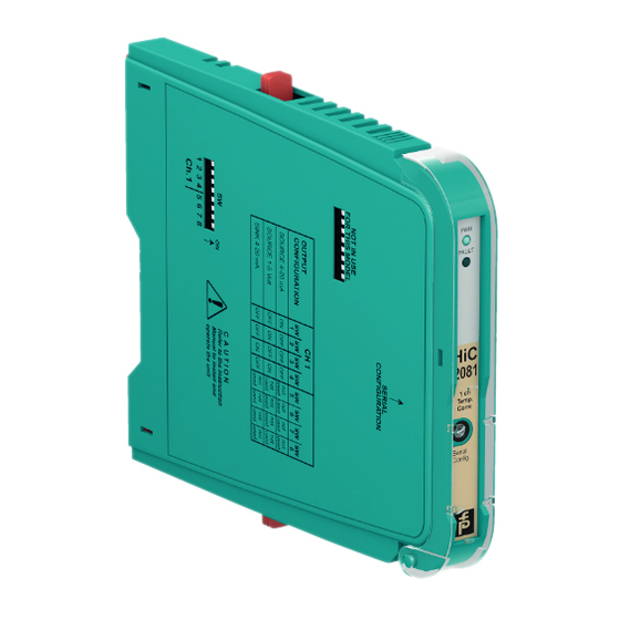
Pepperl+Fuchs HiC2081 Manual
Temperature converter
Hide thumbs
Also See for HiC2081:
- Manual (32 pages) ,
- System manual (48 pages) ,
- System manual (46 pages)
Table of Contents
Advertisement
Quick Links
Advertisement
Table of Contents


Need help?
Do you have a question about the HiC2081 and is the answer not in the manual?
Questions and answers