Table of Contents
Advertisement
Quick Links
Advertisement
Table of Contents

Related Manuals for Pepperl+Fuchs WCS


Summary of Contents for Pepperl+Fuchs WCS
- Page 1 WCS position encoding system Mechanics Manual...
- Page 2 Phone: +49 621 776 - 0 E-mail: info@de.pepperl-fuchs.com North American Headquarters Pepperl+Fuchs Inc. 1600 Enterprise Parkway Twinsburg, Ohio 44087 Phone: +1 330 425-3555 E-mail: sales@us.pepperl-fuchs.com Asia Headquarters Pepperl+Fuchs Pte. Ltd. P+F Building 18 Ayer Rajah Crescent Singapore 139942 Phone: +65 6779-9091 E-mail: sales@sg.pepperl-fuchs.com https://www.pepperl-fuchs.com...
-
Page 3: Table Of Contents
WCS position encoding system Contents Introduction........................ 5 Content of this Document ................5 Target Group, Personnel ................5 Symbols Used ....................6 Product Description ....................7 Functional Description .................. 7 Areas of Use ....................10 Read Head ........................ 13 Introduction ....................13 Overview ....................... - Page 4 Suspended Mounting with Stainless Steel Code Rail....... 52 6.4.8 Grounding the Aluminum Profile System .......... 53 6.4.9 Integration of the WCS Code Rail in Conductor Lines ...... 54 Mounting the WCS2 Code Rail with the Aluminum Profile System..55 6.5.1 Introduction ..................55 6.5.2...
-
Page 5: Introduction
WCS position encoding system Introduction Introduction Content of this Document This document contains information required to use the product in the relevant phases of the product life cycle. This may include information on the following: • Product identification • Delivery, transport, and storage •... -
Page 6: Symbols Used
WCS position encoding system Introduction Symbols Used This document contains symbols for the identification of warning messages and of informative messages. Warning Messages You will find warning messages, whenever dangers may arise from your actions. It is mandatory that you observe these warning messages for your personal safety and in order to avoid prop- erty damage. -
Page 7: Product Description
485 interface and address each separately. This makes it easy to extend your plant at a later stage. In addition to automatic contamination detection, there are other optional extensions for the WCS read head. The options are indicated in the type code with the corresponding letter:... - Page 8 In this case, the code rail is inserted into an extruded aluminum profile developed for the WCS and fixed in place with a fixing cord. The aluminum profile rail is clipped to plastic brackets and attached to the surface with a C profile.
- Page 9 Up to 327 m (WCS2) • Up to 314.573 m (WCS3) • Up to 629.146 m (WCS Extended) • The coding system is also suitable for curves with a radius of up to 0.5 m (does not apply to systems with guide trolleys) •...
-
Page 10: Areas Of Use
Use of multiple vehicles in a row Due to the large tolerance between the read head and code rail, the WCS can be used for most applications. In some cases, however, it is advantageous to use the WCS with a special protec- tive enclosure or a guide trolley in conjunction with the aluminum profile system. - Page 11 Optional cleaning brushes for the code rail can be attached to the guide trolley. This means that the WCS can be used in a very dusty environment, such as in cement works or foundries. If the cranes are used outdoors, the WCS3 is used with a special protective enclosure.
- Page 12 After a power failure, the current position of the vehicle is transferred to the control panel immediately; the vehicle does not have to be moved. The WCS can also be used for distances longer than 314.573 m.
-
Page 13: Read Head
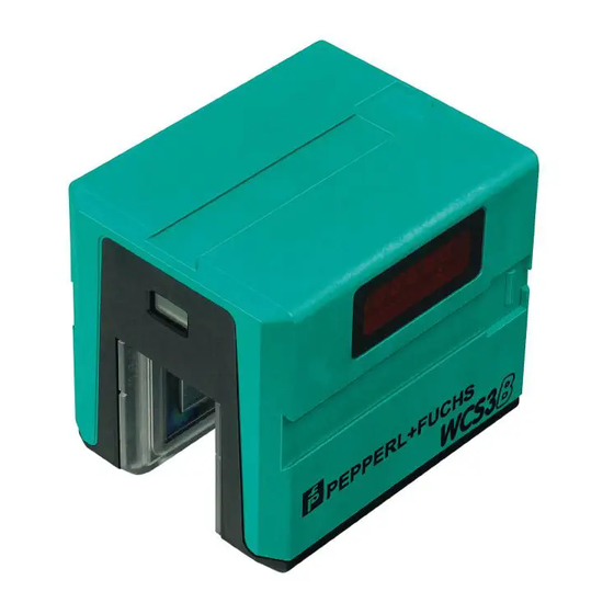
WCS position encoding system Read Head Read Head Introduction The enclosure of the read head is made from robust plastic and has degree of protection IP54. The mounting base for securing the read head is included in the scope of delivery. On the inside of the read head there are easily removable, transparent plastic lenses that protect the reading area against dirt and damage. - Page 14 WCS position encoding system Read Head WCS3B WCS3B read heads have a gap width of 31 mm. This allows a greater tolerance when mount- ing the read head and aligning it in relation to the code rail. WCS3B systems are ideal for mon- itoring conveyor belts and automated warehouse and lifting systems.
-
Page 15: Tolerances
WCS position encoding system Read Head Tolerances Tolerance for Y and Z Axis Figure 3.4 Tolerance for Y and Z axis WCS2B WCS3B WCS3-Outdoor Y axis ± 5 mm ± 15.5 mm ± 12 mm Z axis ± 5 mm ±... - Page 16 WCS position encoding system Read Head Tolerance for Inclined Position β Figure 3.6 Tolerance for inclined position WCS2B WCS3B WCS3-Outdoor ±5° ±5° ±4° ...
-
Page 17: Mounting The Read Head
WCS position encoding system Mounting the Read Head Mounting the Read Head Attaching the Mounting Base As a rule, the read head is mounted on the vehicle. However, the read head can also be mounted stationary. A code rail piece can also be mounted on the carriage (vehicle identifica- tion). - Page 18 WCS position encoding system Mounting the Read Head Securing the Mounting Base Plan elongated holes in the design of the fixture on the carriage. These allow you to correct the position of the mounting base and thus the read head during mounting.
-
Page 19: Replacing Plastic Lenses
WCS position encoding system Mounting the Read Head Replacing Plastic Lenses In the event of damage or contamination, you can replace the plastic lenses on the inside of the read head gap. Replacing Plastic Lenses Loosen two screws on each lens. -
Page 20: Retrofitting The Outdoor Protective Enclosure
WCS position encoding system Mounting the Read Head Retrofitting the Outdoor Protective Enclosure WCS3B-read heads using RS-485, SSI, and CANopen interfaces can be retrofitted with the enclosure. Read heads with EtherNet/IP and PROFINET interfaces can only be used as pre- assembled devices. - Page 21 WCS position encoding system Mounting the Read Head Figure 4.5 Attaching the connection cable Insert the connection cable through one of the three thru-holes in the protective lid and tighten the plug using the special tool. The maximum tightening torque is 1.5 Nm.
- Page 22 WCS position encoding system Mounting the Read Head Figure 4.7 Mounting the protective cover Secure the protective cover to the protective lid with four stainless steel screws and four washers. The maximum tightening torque is 1 Nm. Tighten the stopping plugs on the two unused interfaces using the special tool.
- Page 23 WCS position encoding system Mounting the Read Head Ordering Information The WCS3B read head with the options -OM, -OL, and -OR are delivered pre-assembled with the outdoor protection enclosure: Figure 4.8 Outdoor protective enclosure cable outlet The options -OM, -OL, and -OR describe the direction of the connector in relation to the nomi- nal direction of travel of the read head.
-
Page 24: Mounting The Outdoor Protective Enclosure
WCS position encoding system Mounting the Read Head Mounting the Outdoor Protective Enclosure Warning! Improper mounting Risk of injury if mounted improperly • Ensure you have sufficient space before starting work. • Take care when using sharp-edged components and always wear safety gloves. - Page 25 WCS position encoding system Mounting the Read Head Mounting and Dismounting the Outdoor Protective Enclosure Attach the outdoor protective enclosure to your plant using M6 screws (1). The maximum torque is 6 Nm. Note We recommend using corrosion-resistant stainless steel screws (A2/8.8).
-
Page 26: Code Rail
WCS position encoding system Code Rail Code Rail Introduction The absolute code rail is different for the WCS2 system and WCS3 system Therefore, the code rail cannot be swapped between the two systems. For WCS3, the height of the code rail is always 70 mm;... - Page 27 WCS position encoding system Code Rail Stainless Steel Code Rail The stainless steel code rail is made from corrosion-resistant spring steel. It is rust-free and is characterized by high mechanical stability and low thermal expansion. The stainless steel code rail can be used in the temperature range -40 °C – 100 °C.
-
Page 28: Identification Via Id-Pads
In total, 1260 differ- ent ID-pads are available. Vehicle number = INT((WCS position value - 30) / 312) + 1 In addition to the calculation of the vehicle number, the position value determined by the read head enables fine positioning of the ID-pad in the read head gap and thus exact positioning of the vehicle. -
Page 29: Mounting The Code Rail
WCS position encoding system Mounting the Code Rail Mounting the Code Rail Introduction With continuous position measurement for a route, you have to mount the code rail in one piece. Depending on the operational conditions, there are various options for securing the code rail: •... -
Page 30: Installation Notes
Vertical or suspended mounting Lateral mounting on a wall Note Outdoor use If using the WCS system outdoors, we recommend mounting the aluminum profile rails horizontally. This will allow dirt and snow to fall down rather than collecting in the read head gap. -
Page 31: Mounting The Code Rail On A Straight Route
WCS position encoding system Mounting the Code Rail 6.2.1 Mounting the Code Rail on a Straight Route Mounting the Code Rail—Straight Route Mount the mounting brackets at an offset of max. 1.25 m along the route on the substructure. Align the mounting brackets. -
Page 32: Mounting In Horizontal Curves
> 1000 mm WCS3-Outdoor with guide trolley Not possible To create curves, the mounting brackets for curves are used together with a special WCS-SP2 stabilizing profile. The stabilizing profile is delivered in a bundle in the length ordered. Note The curve brackets are designed so that there is no height or transverse offset of the code rail in the transition from the straight section into the curve. - Page 33 Circular Path Note the following special features of a closed route (circular path, oval, etc.): due to the operating mode of the WCS, you cannot route the code rail continuously along the entire circuit. Maintain an offset of at least 85 mm between the beginning and the end of the code rail (see chapter 6.2.4).
-
Page 34: Mounting In Vertical Curves
WCS position encoding system Mounting the Code Rail 6.2.3 Mounting in Vertical Curves In addition to horizontal curves, vertical curves are required to create inclines/declines. Figure 6.4 Vertical curves Vertical curves up to a minimum radius of 4 m can be created with the aluminum profile in con- junction with the laminate code rail. -
Page 35: Interruptions In The Profile Rail
The principle of the WCS allows for interruptions in the code rail. A minimum distance of 85 mm must be maintained between each pair of code rail segments for the interruption. The read head recognizes when it leaves the code rail and reports "OUT"... -
Page 36: Mounting The Code Rail With Mounting Brackets
WCS position encoding system Mounting the Code Rail Mounting the Code Rail with Mounting Brackets 6.3.1 Introduction The bracket system is an easy way to mount laminate or stainless steel code rails. It consists of brackets for routing the code rail in straight sections, as well as brackets for routing the code rail in curves and circular paths. -
Page 37: System Overview
M6 x 12 WCS-MB1/WCS-MB1-C WCS-MB2/WCS-MB2-C Screw connection with M6 screws Screw connection with C groove The brackets are made from galvanized sheet steel and are supplied pre-assembled. Various versions of the mounting brackets for installation of the WCS code rail are available:... - Page 38 WCS position encoding system Mounting the Code Rail Product name Description Product photo WCS-MB Bracket for straight sections WCS-MB1 Bracket for straight sections With M6 screw connection WCS-MB2 Bracket for straight sections With C t-slide WCS-MB-C Bracket for straight sections...
- Page 39 WCS position encoding system Mounting the Code Rail Note The recommended support distance for straight section elements is at least one bracket every 1.25 m. Mounting Bracket for Curves or Circular Paths M4 x 12 3.5 x 6.5 M6 x 20 M4 x 12 3.5 x 6.2...
- Page 40 WCS-MB2-B-C Powder-coated bracket for curves With C t-slide WCS-SP2 Stabilizing profile For curved sections Note The recommended support distance for curves is at least one bracket every 0.5 m. A WCS- SP2 stabilizing profile must also be used in curves.
-
Page 41: Attaching The Tensioning Device
WCS position encoding system Mounting the Code Rail 6.3.3 Attaching the Tensioning Device Using the tensioning device prevents the stainless steel code rail from warping due to tempera- ture fluctuations after mounting. It also makes mounting easier. Note Pretensioning of the stainless steel code rail is not necessary for system function. -
Page 42: Mounting The Wcs3 Code Rail With The Aluminum Profile System
WCS position encoding system Mounting the Code Rail Mounting the WCS3 Code Rail with the Aluminum Profile System 6.4.1 Introduction A special aluminum profile system has been developed for quick mounting of the 70 mm WCS3 code rail made from plastic laminate or stainless steel. The aluminum profile is designed such that it supports the code rail. -
Page 43: System Overview
WCS position encoding system Mounting the Code Rail 6.4.2 System Overview Figure 6.10 Overview Item Designation Product name Note Fixing cord WCS-MF1 Rail holder WCS3-MH* Support distances for perpendicular/sus- pended mounting: < 2.5 m, lateral mounting: < 2 m Aluminum profile rail... - Page 44 WCS position encoding system Mounting the Code Rail Read Head with WCS3 Profile Rail 1. WCS3 profile system with rail holder mounted on C profile rail, with read head 2. WCS3 profile system with rail holder mounted on C profile rail, with outdoor protective en-...
-
Page 45: Rail Holder
WCS position encoding system Mounting the Code Rail 6.4.3 Rail Holder Mounting the Rail Holders Mount the rail holders at an offset of 2 m along the route on the substructure for a lateral mounting and 2.5 m for a perpendicular or suspended mounting. -
Page 46: Butt Connectors For Profile Rails
WCS position encoding system Mounting the Code Rail 6.4.4 Butt Connectors for Profile Rails Butt connectors are required for connecting aluminum profile rails. The WCS3-MC1 butt con- nector consists of a 170 mm long extruded aluminum profile and two self-tapping screws. - Page 47 WCS position encoding system Mounting the Code Rail Note When you slide the aluminum profile rails together with the butt connectors, make sure there is a gap to compensate for thermal expansion. A gap is necessary if the maximum possible operating temperature is greater than the temperature during the assembly.
-
Page 48: Mounting The Code Rail
WCS position encoding system Mounting the Code Rail 6.4.5 Mounting the Code Rail Mounting the Code Rail in the Profile Rail Insert the code rail into the groove of the profile rail. Figure 6.13 Mounting the code rail Fix the code rail in place by pressing the plastic fixing cord into the groove of the profile rail and simultaneously pressing on the code rail. - Page 49 WCS position encoding system Mounting the Code Rail Figure 6.14 Mounting tool This ensures that the fixing cord sits correctly in the groove. The contact pressure of the fixing cord is so great that the code rail cannot slip out of the profile rail even when it is mounted suspended.
-
Page 50: Fixed Points
WCS position encoding system Mounting the Code Rail 6.4.6 Fixed Points To prevent the aluminum profile rails slipping in the rail holders when mounted horizontally, the profile must be securely connected to the substructure. Positioning a Fixed Point Position a fixed point in the middle of the section that you want to fix in place. - Page 51 WCS position encoding system Mounting the Code Rail We recommend that you fix the aluminum profile in place at multiple points along a route using the method described. Make sure that there are sufficient expansion gaps between the aluminum profiles (see chapter 6.4.4).
-
Page 52: Suspended Mounting With Stainless Steel Code Rail
WCS position encoding system Mounting the Code Rail 6.4.7 Suspended Mounting with Stainless Steel Code Rail If you want to mount the stainless steel code rail suspended, you have to secure the code rail against falling down. This applies in particular when there are frequent changes in temperature. -
Page 53: Grounding The Aluminum Profile System
WCS position encoding system Mounting the Code Rail Figure 6.18 Screwing in a self-tapping screw 6.4.8 Grounding the Aluminum Profile System Connect the aluminum profile with the plant potential at low resistance at least every 30 m. Figure 6.19 Grounding... -
Page 54: Integration Of The Wcs Code Rail In Conductor Lines
This requirement was taken into account in the development of the new Vahle VKS 10 conduc- tor line. The VKS 10 is flexible in terms of the number of conductors and cross-sections and facilitates cost-effective integration of the WCS code rail in the plastic base body of the conduc- tor line. -
Page 55: Mounting The Wcs2 Code Rail With The Aluminum Profile System
WCS system. At the same time, the read head is decoupled from vehicle vibrations. The aluminum profile system is mounted in a perpendicular and suspended position. -
Page 56: System Description
WCS position encoding system Mounting the Code Rail 6.5.2 System Description WCS2 Read Head with Guide Trolley Figure 6.21 Overview Item Designation Product name Note Fixing cord WCS-MF1 WCS read head WCS2B-LS** Guide trolley WCS2-GT* Aluminum profile rail WCS2-PS1(-C) 2.5 m or 5 m long,... - Page 57 WCS position encoding system Mounting the Code Rail WCS3 Read Head with Outdoor Protective Enclosure and Guide Trolley Figure 6.22 Overview Item Designation Product name Note Fixing cord WCS-MF1 WCS3-Outdoor WCS3B-LS*-O* Read head with outdoor protective enclosure Guide trolley WCS3-GT09-P1-O...
- Page 58 WCS position encoding system Mounting the Code Rail WCS Read Head with Profile Rail 1. WCS2 profile system with rail holder mounted on C profile rail, with read head in the guide trolley 2. WCS2 profile system with rail holder mounted on C profile rail, with the WCS3-Outdoor...
-
Page 59: Rail Holder
WCS position encoding system Mounting the Code Rail 6.5.3 Rail Holder Mounting the Rail Holders Mount the rail holders at intervals of 1.5 m along the route on the substructure for a perpendicular or suspended mounting. Note For lateral mounting with a WCS2 guide trolley, the support distance must be reduced to 1.25 m. -
Page 60: Butt Connectors For Profile Rails
WCS position encoding system Mounting the Code Rail 6.5.4 Butt Connectors for Profile Rails Butt connectors are required for connecting aluminum profile rails. The WCS2-MC* butt con- nector consists of two flat pieces and four self-tapping screws. 45.0 Figure 6.25... - Page 61 WCS position encoding system Mounting the Code Rail The tips of the screws press into the aluminum profile and fix the butt connector in place. Slide the profile rails together with the butt connectors. Note When you slide the aluminum profile rails together with the butt connectors, make sure there is a gap to compensate for thermal expansion.
- Page 62 WCS position encoding system Mounting the Code Rail Calculate the necessary gap width as follows: Gap width in mm = 0.11 * = - max. operating temp. assembly temp. Examples: = 10 K, gap width = 1.1 mm ...
-
Page 63: Mounting The Code Rail
WCS position encoding system Mounting the Code Rail 6.5.5 Mounting the Code Rail Mounting the Code Rail in the Profile Rail Insert the code rail into the groove of the profile rail. Fix the code rail in place by pressing the plastic fixing cord into the groove of the profile rail and simultaneously pressing on the code rail. - Page 64 WCS position encoding system Mounting the Code Rail This ensures that the fixing cord sits correctly in the groove. The contact pressure of the fixing cord is so great that the code rail cannot slip out of the profile rail even when it is mounted suspended.
-
Page 65: Fixed Points
WCS position encoding system Mounting the Code Rail 6.5.6 Fixed Points When the rails are mounted horizontally, a locking bracket is required to prevent the aluminum profile rails slipping in the rail holders. Designation Part number Function/use Material WCS2-LB1 184048... - Page 66 WCS position encoding system Mounting the Code Rail To ensure that the code rail does not slip in the aluminum profile rail, you can fix the code rail in place by using a spring dowel pin or a self-tapping screw in the middle of the section.
-
Page 67: Guide Trolley
WCS position encoding system Mounting the Code Rail 6.5.7 Guide Trolley Caution! When mounting and using the tappet, make sure that the guide trolley is not subjected to any forces. There must be no rigid connection between the vehicle and the guide trolley. - Page 68 The guide trolley housing has holes for mounting cleaning brushes for the code rail. The cleaning brushes (optional) are only necessary if the code holes in the WCS code rail can become clogged as a result of the application, e.g., with bird feathers or leaves. The brushes can also be retrofitted.
- Page 69 WCS position encoding system Mounting the Code Rail Guide Trolley for the WCS3-Outdoor Read Head with Protective Enclosure The protective enclosure with the read head is mounted in the guide trolley (WCS3-GT09-P1- O). The guide trolley is guided over the profile rails to the optimal position between the protec- tive enclosure and code rail.
-
Page 70: Grounding The Aluminum Profile System
WCS position encoding system Mounting the Code Rail To dismount, loosen the four fastening screws. Remove the protective enclosure from the guide trolley. Note More information, as well as detailed mounting instructions are included with the guide trolley. These mounting instructions are also available at www.pepperl-fuchs.com. -
Page 71: Wcs3 Code Rail Extender For "Extended" Read Heads
WCS position encoding system Mounting the Code Rail WCS3 Code Rail Extender for "Extended" Read Heads 6.6.1 Introduction The WCS3 code rail extender is used to extend the WCS3 code rail system. The WCS3 code rail extender connects two code rail segments to achieve lengths up to a maximum of 629.146 m. -
Page 72: Mounting The Wcs3 Code Rail Extender
WCS position encoding system Mounting the Code Rail 6.6.3 Mounting the WCS3 Code Rail Extender Connecting the Code Rail (Aluminum Profile System) Caution! Improper mounting! • Always mount the WCS3 code rail extender at end position 314.573 m. • A complete code rail segment always begins at 0 m and ends at 314.573 m. - Page 73 WCS position encoding system Mounting the Code Rail Figure 6.36 Fixing the WCS3 code rail extender in place To prevent the WCS3 code rail extender from slipping, you can fix the WCS3 code rail extender in place with the code rail by using spring dowels in the additional holes, as seen in the figure.
- Page 74 WCS position encoding system Mounting the Code Rail Figure 6.38 Fixing the WCS3 code rail extender in place When mounted correctly, the tensioning force on the brackets is so great that the code rail can no longer be pulled out of the bracket.
-
Page 75: Maintenance
WCS position encoding system Maintenance Maintenance Danger! Danger to life due to electrical current! Contact with live parts causes immediate danger to life. • Allow only qualified electricians to carry out work on the electrical installation. • Switch off the power supply before carrying out servicing, cleaning, and repairs, and pre- vent the supply from being switched on again. -
Page 76: Repairs
Damage to the Code Rail For high-quality and lasting results, the use of original Pepperl+Fuchs code rails is recom- mended. The procedure for replacing damaged code rail sections is described below. - Page 77 WCS position encoding system Maintenance Weld the two code rails to each other at four points, e.g., using shielding gas welding equipment. Note Alternatively, you can connect the code rails using blind rivets. Blind rivets can be used only on the upper edges of the code rails because they do not fit in the V-groove of the aluminum profile.
-
Page 78: Wcs Stainless Steel Code Rail (Mounting Bracket System)
WCS Stainless Steel Code Rail (Mounting Bracket System) Replacing a Damaged Section When ordering the replacement code rail, specify the beginning and end position, as well the 10 double hollow rivets (WCS-CS-RV) for connecting the replacement code rail with the existing code rail. Start Determine the position values in front of and behind the damaged area. -
Page 79: Wcs Laminate Code Rail (Aluminum Profile)
WCS Laminate Code Rail (Aluminum Profile) Replacing a Damaged Section When ordering the replacement code rail, specify the beginning and end position, as well the 10 double hollow rivets (WCS-CS-RV) for connecting the replacement code rail with the existing code rail. Start Determine the position values in front of and behind the damaged area. - Page 80 WCS position encoding system Maintenance The code rail holds together firmly. Insert the repaired code rail back into the aluminum profile and press the fixing cord in to reinsert it.
-
Page 81: Wcs Laminate Code Rail (Mounting Bracket System)
WCS Laminate Code Rail (Mounting Bracket System) Replacing a Damaged Section When ordering the replacement code rail, specify the beginning and end position, as well the 10 double hollow rivets (WCS-CS-RV) for connecting the replacement code rail with the existing code rail. Start Determine the position values in front of and behind the damaged area. - Page 82 WCS position encoding system Maintenance Tighten the code rail slightly as needed.
-
Page 83: Model Overview For Wcs Read Heads
WCS position encoding system Model Overview for WCS Read Heads Model Overview for WCS Read Heads WCS.-LS ..Lesekopfadresse Option(en) Datenprotokoll Baudrate Hardware Type WCS2B read head (smaller enclosure, 1200 pos./m with a maximum of 327 m) WCS3B read head (1250 pos./m with a maximum of... - Page 84 WCS position encoding system Model Overview for WCS Read Heads Data log Read head with RS-485 interface Data log 1, data log 2 Data log 3 with even parity (9 bit/byte) Data log 3 without parity (8 bit/byte) Read head with SSI interface...
-
Page 85: Disposal
WCS position encoding system Disposal Disposal The device, built-in components, packaging, and any batteries contained within must be dis- posed in compliance with the applicable laws and guidelines of the respective country. -
Page 86: Appendix
Appendix 10.1 Cable Overview The cable types listed below represent a selection of the types offered by Pepperl+Fuchs. Fur- ther cable types can be found on our website. Note For cables that you can assemble yourself, observe the cable length restrictions specified by the interface specification. - Page 87 WCS position encoding system Appendix SSI (LS3xx*) Cable Description Pre-configured cable V19-G-2M-PUR-ABG M12 single-ended female cordset, eight-pin, straight, 2 m PUR cable, shielded, V19-G-5M-PUR-ABG M12 single-ended female cordset, eight-pin, straight, 5 m PUR cable, shielded, V19-G-10M-PUR- M12 single-ended female cordset, eight-pin, straight, 10 m PUR...
- Page 88 WCS position encoding system Appendix EtherNet/IP (LS5xx*) & PROFINET (LS6xx*) Cable Description Hybrid cable with common data line and supply voltage V19SY-G-BK2M- Single-ended male cordset, M12, 8-pin, Y coding, 2 m PUR cable, PUR-ABG shielded V19SY-G-BK5M- Single-ended male cordset, M12, 8-pin, Y coding, 5 m PUR cable,...
- Page 89 Pepperl+Fuchs Quality Download our latest policy here: www.pepperl-fuchs.com/quality www.pepperl-fuchs.com © Pepperl+Fuchs · Subject to modifications Printed in Germany / DOCT-3785...
Need help?
Do you have a question about the WCS and is the answer not in the manual?
Questions and answers