
Related Manuals for Pepperl+Fuchs KCD2-UT2-1


Summary of Contents for Pepperl+Fuchs KCD2-UT2-1
- Page 1 PROCESS AUTOMATION MANUAL Functional Safety Temperature Converter KCD2-UT2-(Ex)1, HiC2081 ISO9001...
- Page 2 Functional Safety KCD2-UT2-(Ex)1, HiC2081 With regard to the supply of products, the current issue of the following document is applicable: The General Terms of Delivery for Products and Services of the Electrical Industry, published by the Central Association of the Electrical Industry (Zentralverband Elektrotechnik und Elektroindustrie (ZVEI) e.V.) in its most recent version as well as the supplementary clause: "Expanded reservation of proprietorship"...
-
Page 3: Table Of Contents
Functional Safety KCD2-UT2-(Ex)1, HiC2081 Content Introduction ........... 4 Content of this Document. -
Page 4: Introduction
Additionally, the following parts may belong to the documentation, if applicable: • EU-type examination certificate • EU declaration of conformity • Attestation of conformity • Certificates • Control drawings • FMEDA report • Assessment report • Additional documents For more information about Pepperl+Fuchs products with functional safety, see www.pepperl- fuchs.com/sil. -
Page 5: Safety Information
Functional Safety KCD2-UT2-(Ex)1, HiC2081 Introduction Safety Information Target Group, Personnel Responsibility for planning, assembly, commissioning, operation, maintenance, and dismounting lies with the plant operator. Only appropriately trained and qualified personnel may carry out mounting, installation, commissioning, operation, maintenance, and dismounting of the product. The personnel must have read and understood the instruction manual and the further documentation. -
Page 6: Symbols Used
Functional Safety KCD2-UT2-(Ex)1, HiC2081 Introduction Symbols Used This document contains symbols for the identification of warning messages and of informative messages. Warning Messages You will find warning messages, whenever dangers may arise from your actions. It is mandatory that you observe these warning messages for your personal safety and in order to avoid property damage. -
Page 7: Product Description
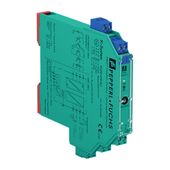
Functional Safety KCD2-UT2-(Ex)1, HiC2081 Product Description Product Description Function KCD2-UT2-1 This signal conditioner provides the galvanic isolation between field circuits and control circuits. The device converts RTD input signals or thermocouple input signals on the field side to 0/4 mA ... 20mA signals on the control side. -
Page 8: Interfaces
For corresponding connections see datasheet. Marking Pepperl+Fuchs GmbH Lilienthalstraße 200, 68307 Mannheim, Germany Internet: www.pepperl-fuchs.com KCD2-UT2-1, KCD2-UT2-Ex1, HiC2081 Up to SIL 2 Standards and Directives for Functional Safety Device-specific standards and directives Functional safety IEC/EN 61508, part 2, edition 2010:... -
Page 9: Planning
Functional Safety KCD2-UT2-(Ex)1, HiC2081 Planning Planning System Structure 3.1.1 Low Demand Mode of Operation If there are two control loops, one for the standard operation and another one for the functional safety, then usually the demand rate for the safety loop is assumed to be less than once per year. -
Page 10: Assumptions
Functional Safety KCD2-UT2-(Ex)1, HiC2081 Planning Assumptions The following assumptions have been made during the FMEDA: • Failure rate based on the Siemens standard SN29500. • Failure rates are constant, wear is not considered. • Failures during configuration are not considered. •... -
Page 11: Safety Function And Safe State
Functional Safety KCD2-UT2-(Ex)1, HiC2081 Planning Safety Function and Safe State Safety Function The safety function of the device is fulfilled, as long as the output repeats the linearized input signal with a tolerance of 2 %. Safe State The safe state is present when the output signal is < 4 mA or > 20 mA. Reaction Time •... -
Page 12: Characteristic Safety Values
Functional Safety KCD2-UT2-(Ex)1, HiC2081 Planning Characteristic Safety Values Parameters Characteristic values Assessment type FMEDA report with proven-in-use assessment Device type Mode of operation Low demand mode or high demand mode SIL (SC) Safety function Transfer of analog signal 20.1 FIT ... -
Page 13: Useful Life Time
As noted in DIN EN 61508-2:2011 note N3, appropriate measures taken by the manufacturer and plant operator can extend the useful lifetime. Our experience has shown that the useful lifetime of a Pepperl+Fuchs product can be higher if the ambient conditions support a long life time, for example if the ambient temperature is significantly below 60 °C. -
Page 14: Mounting And Installation
Functional Safety KCD2-UT2-(Ex)1, HiC2081 Mounting and Installation Mounting and Installation Mounting and Installing the Device 1. Observe the safety instructions in the instruction manual. 2. Observe the information in the manual. 3. Observe the requirements for the safety loop. 4. Protect the device against manipulation. Mount the device in a lockable switch cabinet, for example. -
Page 15: Operation
Functional Safety KCD2-UT2-(Ex)1, HiC2081 Operation Operation Danger! Danger to life from missing safety function If the safety loop is put out of service, the safety function is no longer guaranteed. • Do not deactivate the device. • Do not bypass the safety function. •... - Page 16 Functional Safety KCD2-UT2-(Ex)1, HiC2081 Operation 5.2.1 Thermocouple Input (TC) Multimeter KCD2-UT2-Ex1 (mA) Sim. 110 Ω Fault Supply + 24 V DC Zone 0, 1, 2 Zone 2 Power I supply Supply Div. 1, 2 Div. 2 supply Supply - Figure 5.1 Proof test set-up for KCD2-UT2-(Ex)1 with thermocouple input (TC) Usage in Zone 0, 1, 2/Div.
- Page 17 Functional Safety KCD2-UT2-(Ex)1, HiC2081 Operation 9. Apply a short circuit between terminal 3 and 4. Check if a short circuit of the cold junction compensation is detected. The red LED is flashing. The output behavior in the event of a fault depends on the device configuration.
- Page 18 Functional Safety KCD2-UT2-(Ex)1, HiC2081 Operation 5.2.2 Resistance Thermometer Input (RTD) Multimeter KCD2-UT2-Ex1 (mA) Fault Supply + 24 V DC Zone 0, 1, 2 Zone 2 Power I supply Supply Div. 1, 2 Div. 2 supply Supply - Figure 5.2 Proof test set-up for KCD2-UT2-(Ex)1 with resistance thermometer input (RTD) Usage in Zone 0, 1, 2/Div.
- Page 19 Functional Safety KCD2-UT2-(Ex)1, HiC2081 Operation 5.2.3 Voltage Input (mV) Multimeter KCD2-UT2-Ex1 (mA) Fault Supply + 24 V DC Zone 0, 1, 2 Zone 2 Power I supply Supply Div. 1, 2 Div. 2 supply Supply - Figure 5.3 Proof test set-up for KCD2-UT2-(Ex)1 with voltage input (mV) Usage in Zone 0, 1, 2/Div.
- Page 20 Functional Safety KCD2-UT2-(Ex)1, HiC2081 Operation 5.2.4 Potentiometer Input Multimeter KCD2-UT2-Ex1 (mA) 50 % 100 % Fault Supply + 24 V DC Zone 0, 1, 2 Zone 2 Power I supply Supply Div. 1, 2 Div. 2 supply Supply - Figure 5.4 Proof test set-up for KCD2-UT2-(Ex)1 with potentiometer input Usage in Zone 0, 1, 2/Div.
- Page 21 Functional Safety KCD2-UT2-(Ex)1, HiC2081 Operation 5.2.5 Additional Versions Proof Test for Output as Current Sink The criteria for a successful repeat test, which are specified for the output as a current source, are also valid for the output as current sink. In addition to the test setup described above, a voltage source must be connected to the output to simulate the original application.
-
Page 22: Proof Test Procedure For Hic2081
Functional Safety KCD2-UT2-(Ex)1, HiC2081 Operation Proof Test Procedure for HiC2081 Perform the proof test with the same configuration that you use in the application. Substitute the sensor with a sensor simulator or a calibrator. Check the safety function at the input, which must be configured to set the output values to 4 mA, 12 mA, 20 mA. - Page 23 Functional Safety KCD2-UT2-(Ex)1, HiC2081 Operation 5.3.1 Thermocouple Input (TC) Termination Board Multimeter HiC2081 (mA) Sim. 110 Ω Supply + Fault 24 V DC Power I supply Supply Zone 0, 1, 2 supply Supply - Figure 5.5 Proof test set-up for HiC2081 with thermocouple input (TC) Proof Test Procedure for the Thermocouple Input Additional equipment: 110 ...
- Page 24 Functional Safety KCD2-UT2-(Ex)1, HiC2081 Operation 9. Apply a short circuit between terminal 1 and 4. Check if a short circuit of the cold junction compensation is detected. The red LED is flashing. The output behavior in the event of a fault depends on the device configuration.
- Page 25 Functional Safety KCD2-UT2-(Ex)1, HiC2081 Operation 5.3.2 Resistance Thermometer Input (RTD) Termination Board Multimeter HiC2081 (mA) Supply + Fault 24 V DC Power I supply Supply Zone 0, 1, 2 supply Supply - Figure 5.6 Proof test set-up for HiC2081 with resistance thermometer input (RTD) Proof Test Procedure for Resistance Thermometer Input 1.
- Page 26 Functional Safety KCD2-UT2-(Ex)1, HiC2081 Operation 5.3.3 Voltage Input (mV) Termination Board Multimeter HiC2081 (mA) Supply + Fault 24 V DC Power I supply Supply Zone 0, 1, 2 supply Supply - Figure 5.7 Proof test set-up for HiC2081 with voltage input (mV) Proof Test Procedure for the Voltage Input 1.
- Page 27 Functional Safety KCD2-UT2-(Ex)1, HiC2081 Operation 5.3.4 Potentiometer Input Termination Board Multimeter HiC2081 (mA) 50 % 100 % Supply + Fault 24 V DC Power I supply Supply Zone 0, 1, 2 supply Supply - Figure 5.8 Proof test set-up for HiC2081 with potentiometer input Proof Test Procedure for the Potentiometer Input The resistor values which are used to simulate the potentiometer shall be chosen so that they represent the full scale value of the potentiometer when connected in series.
- Page 28 Functional Safety KCD2-UT2-(Ex)1, HiC2081 Operation 5.3.5 Additional Versions Proof Test for Output as Current Sink The criteria for a successful repeat test, which are specified for the output as a current source, are also valid for the output as current sink. In addition to the test setup described above, a voltage source must be connected to the output to simulate the original application.
-
Page 29: Maintenance And Repair
Functional Safety KCD2-UT2-(Ex)1, HiC2081 Maintenance and Repair Maintenance and Repair Danger! Danger to life from missing safety function If the safety loop is put out of service, the safety function is no longer guaranteed. • Do not deactivate the device. •... -
Page 30: List Of Abbreviations
Functional Safety KCD2-UT2-(Ex)1, HiC2081 List of Abbreviations List of Abbreviations Emergency Shutdown Failure In Time in 10 FMEDA Failure Mode, Effects, and Diagnostics Analysis Probability of safe failure Probability of dangerous detected failure Probability of dangerous undetected failure ... - Page 31 Functional Safety KCD2-UT2-(Ex)1, HiC2081 Notes...
- Page 32 PROCESS AUTOMATION – PROTECTING YOUR PROCESS Worldwide Headquarters Pepperl+Fuchs GmbH 68307 Mannheim · Germany Tel. +49 621 776-0 E-mail: info@de.pepperl-fuchs.com For the Pepperl+Fuchs representative closest to you check www.pepperl-fuchs.com/contact www.pepperl-fuchs.com Subject to modifications DOCT-5949A Copyright PEPPERL+FUCHS • Printed in Germany 02/2018...
Need help?
Do you have a question about the KCD2-UT2-1 and is the answer not in the manual?
Questions and answers