Table of Contents
Advertisement
Quick Links
Advertisement
Table of Contents

Related Manuals for Pepperl+Fuchs PSC2.CP.SR.26.26.16-Y7017109


Summary of Contents for Pepperl+Fuchs PSC2.CP.SR.26.26.16-Y7017109
- Page 1 Fiber Optic Media Converter PSC2.CP.SR.26.26.16- Y7017109* Manual...
- Page 2 Phone: +49 621 776 - 0 E-mail: info@de.pepperl-fuchs.com North American Headquarters Pepperl+Fuchs Inc. 1600 Enterprise Parkway Twinsburg, Ohio 44087 Phone: +1 330 425-3555 E-mail: sales@us.pepperl-fuchs.com Asia Headquarters Pepperl+Fuchs Pte. Ltd. P+F Building 18 Ayer Rajah Crescent Singapore 139942 Phone: +65 6779-9091 E-mail: sales@sg.pepperl-fuchs.com https://www.pepperl-fuchs.com...
-
Page 3: Table Of Contents
Fiber Optic Media Converter Box Contents Introduction........................ 4 Content of this Document ................4 Manufacturer ....................4 Target Group, Personnel ................4 Symbols Used ....................5 General Description ....................6 Intended Use ....................6 Certification....................6 Marking ......................6 Labels ......................6 Components .................... -
Page 4: Introduction
• Certificates • Control drawings • Functional safety manual • Additional documents Manufacturer Pepperl+Fuchs Group Lilienthalstraße 200, 68307 Mannheim, Germany Internet: www.pepperl-fuchs.com Target Group, Personnel Responsibility for planning, assembly, commissioning, operation, maintenance, and dismount- ing lies with the plant operator. -
Page 5: Symbols Used
Fiber Optic Media Converter Box Introduction Only appropriately trained and qualified personnel may carry out mounting, installation, com- missioning, operation, maintenance, and dismounting of the product. The personnel must have read and understood the instruction manual and the further documentation. Prior to using the product make yourself familiar with it. -
Page 6: General Description
Fiber Optic Media Converter Box General Description General Description Intended Use The fiber optic media converter box is used to extend the communication range between Ether- net devices to communicate over longer distances, improving network flexibility. The fiber optic media converter box can connect up to 4 Ethernet devices to a fiber optic network. Certification The device is certified for use in hazardous areas up to ATEX/IECEx Zone 2/22 and NEC Class I, II, Div. - Page 7 Fiber Optic Media Converter Box General Description ATEX/IECEx Certification Label (lid outside): UL-Certification Label (lid inside): Figure 2.3 Field Wiring Guide Figure 2.4...
-
Page 8: Components
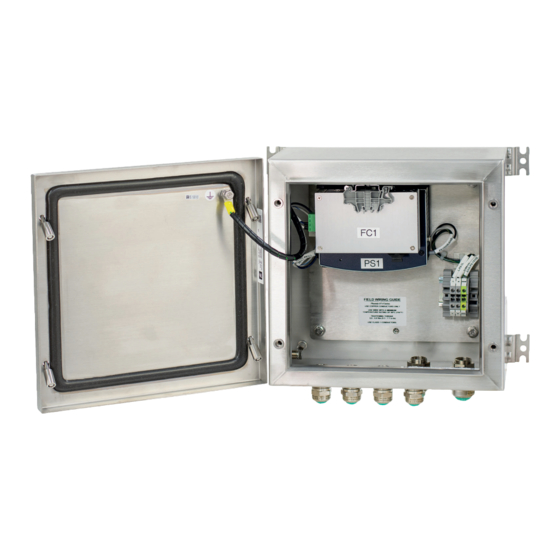
Fiber Optic Media Converter Box General Description Note For labels of the components please refer to the corresponding datasheet (see next chapter). Components This product consists of: Figure 2.5 Component Note Ethernet Fiber Optic Switch EDS-205A Please refer to the technical datasheet for Series (T-models) more information: https://www.moxa.com Power supply PS1000-A6-24.5... -
Page 9: Application Scenarios
Fiber Optic Media Converter Box General Description Application Scenarios 4x HMI (Multimode, DC) Figure 2.6 4x Ethernet Devices (Multimode, DC) Figure 2.7... - Page 10 Fiber Optic Media Converter Box General Description 4x HMI (Multimode, AC) Figure 2.8 4x HMI (Multimode) Figure 2.9...
- Page 11 Fiber Optic Media Converter Box General Description Partial Redundancy (Multimode, DC) Figure 2.10 Full Redundancy (Multimode, DC) Figure 2.11 Warning! No other device can be connected to the power supply but the already connected media con- verter. Connecting another device can lead to permanent damage. Note When connecting a single-mode fiber optic transceiver, it is recommended to use an attenuator to avoid damage caused by excessive optical power.
-
Page 12: Technical Data
Fiber Optic Media Converter Box Technical data Technical data Manufacturer Pepperl+Fuchs SE Lilienthalstraße 200 68307 Mannheim Germany Manufacturing location Pepperl+Fuchs, Inc. 502 Cane Island Parkway Katy, TX 77494 Mechanical specifications Material Glass fiber reinforced polyester Degree of protection IP66 / TYPE 4X... - Page 13 Fiber Optic Media Converter Box Technical data Data for application in connection with hazardous areas Applied standards For ETLus: NFPA 70 (NEC) UL50-2007 UL50E-2007 UL508A UL 121201 For cETL: CSA C22.2 No.14 CSA 22.1-12 (CEC) CSA C22.2 No. 94.1-07 CSA C22.2 No. 94.2-07 CSA C22.2 No.
-
Page 14: Installation And Commissioning
The use of the device is only permitted under the ambient conditions (temperature, humidity, vibration and shock) which are specified in the technical data. Failure to comply with any of these conditions void the warranty for the device. Pepperl+Fuchs cannot be held liable for any damage arising from improper use and handling. -
Page 15: Opening The Housing
Fiber Optic Media Converter Box Installation and Commissioning Opening the housing Loosen the 4 screws on the housing cover Figure 4.1 Disconnect the grounding cable from the housing cover. Figure 4.2 Mount the housing in the required location (wall mount is recommended). -
Page 16: Connecting The Dc Power Supply
Fiber Optic Media Converter Box Installation and Commissioning Connecting the DC power supply The cable glands for the DC options PSC2.CP.SR.26.26.16-Y70171098 (Part No.: 70171098) and PSC2.CP.SR.26.26.16-Y70171099 (Part No.: 70171099) are arranged as follows: Loosen the cable gland #3 (see picture). Figure 4.3 Description Ethernet Cable... - Page 17 Fiber Optic Media Converter Box Installation and Commissioning The cable glands have 3 different seal combinations, depending on the cable diameter. Each seal combination has a possible cable diameter and a specific torque value. Figure 4.4 Seal combination for M20 gland (for AC option, Part-No: #291258) Seal combination Torque value Diameter...
- Page 18 Fiber Optic Media Converter Box Installation and Commissioning Figure 4.5...
- Page 19 Fiber Optic Media Converter Box Installation and Commissioning Guide the cable through the cable gland (3) into the inside of the box. Figure 4.6 Pull out the green connector from the Moxa Switch and connect the DC power supply cable as shown.
- Page 20 Fiber Optic Media Converter Box Installation and Commissioning Figure 4.8 Figure 4.9 Tighten the cable gland with the specific torque value (see table for M20s).
-
Page 21: Connecting The Ac Power Supply
For further information regarding the AC power supply please refer to the PS1000 manual for instructions. In the chapter "Electrical Installation" you can find further instructions on how to connect the AC power supply. The manual can be found at www.pepperl+fuchs.com. Note The diameter of the power cable depends on the selected seal (see table above). - Page 22 Fiber Optic Media Converter Box Installation and Commissioning Prepare the power supply cable. Adjust the cable gland to the diameter of the cable (see table in previous chapter).
- Page 23 Fiber Optic Media Converter Box Installation and Commissioning Guide the cable through the cable gland (3) into the inside of the box. Tighten the screws on the connector with a torque of 0.6 - 0.8 Nm. Figure 4.11 Tighten the cable gland with the specific torque value (see table for M20).
-
Page 24: Connecting The Fiber Optic Cable To The Fiber Optic Switch
Fiber Optic Media Converter Box Installation and Commissioning Connecting the fiber optic cable to the fiber optic switch Loosen the cable gland #4 shown in the drawing above (same for AC and DC). Prepare the FO cable. Adjust the cable gland to the diameter of the cable (see table in chapter). Figure 4.12 Insert the field FO cable (trimmed cable) into the cable gland. - Page 25 Fiber Optic Media Converter Box Installation and Commissioning Splice the trimmed FO cable to the FO connector (for example SC connector). Figure 4.14 Remove the black blind plug from the FO switch and connect the FO cable to the FO plug on the switch.
- Page 26 Fiber Optic Media Converter Box Installation and Commissioning Figure 4.15 Tighten the cable gland with the specific torque value (see table above) Figure 4.16...
-
Page 27: Connecting The Field Ethernet Cable To The Fo Switch
Fiber Optic Media Converter Box Installation and Commissioning Note The diameter of the power cable depends on the selected seal (see table 2). Warning! The power cable passing through the cable gland should have a cable sheath to ensure Ex conformity. - Page 28 Fiber Optic Media Converter Box Installation and Commissioning Guide the cable through the cable gland into the inside of the box. Figure 4.18 Connect the trimmed Ethernet cable to a RJ45 field connector ST-RJ45-1-BTR (Part No.: #218119). Figure 4.19 Connect the Ethernet cable to one of the four Ethernet plugs on the FO switch...
- Page 29 Fiber Optic Media Converter Box Installation and Commissioning Figure 4.20 Tighten the cable gland with the specific torque value (see table in chapter 4.2). Note The diameter of the power cable depends on the selected seal (see table 2). Warning! The power cable passing through the cable gland should have a cable sheath to ensure Ex conformity.
-
Page 30: Closing The Lid
Fiber Optic Media Converter Box Installation and Commissioning Up to 4 Ethernet devices can be added: Figure 4.21 Figure 4.22 Closing The Lid Before closing the housing, reconnect the grounding cable to the lid. Tighten the 4 screws of the housing cover with a torque of 3 - 3.5 Nm. -
Page 31: Installer Notes
Fiber Optic Media Converter Box Installation and Commissioning Installer Notes INSTALLER NOTE FOR ATEX / IECEx SOLUTIONS: Install per applicable local, state, or national standards and/or Directives, including but not lim- ited to IEC/EN 60079-0, 60079-7, 60079-14, 60079-15, 60079-31. INSTALLER NOTE FOR NORTH AMERICAN SOLUTIONS: A branch circuit protective device (fuse or circuit breaker) complying with UL508A Section 40 must be installed on the load side of any supplying ungrounded conductor to this circuit and shall be rated for 1.5 A. -
Page 32: Fault Elimination
Fiber Optic Media Converter Box Fault elimination Fault elimination Control panels and the electrical and electronic devices which are used in explosion-hazard- ous area applications must not be altered in any way. In the event of a fault, the control panel or the device(s) must be replaced. Defective enclosure parts must be replaced with original parts only. -
Page 33: Maintenance
Fiber Optic Media Converter Box Maintenance Maintenance The equipment supplied is essentially maintenance free, however the following maintenance procedure or checks should be undertaken in order to ensure the safe operation of the equip- ment: Caution! To avoid electrostatics charging, the enclosure or installed equipment should only be wiped or cleaned using a damp cloth. -
Page 34: Disposal
Fiber Optic Media Converter Box Disposal Disposal The packaging materials and the control panel must be disposed of in accordance with the reg- ulations pertaining to the country in which they are installed. No batteries which must be separately disposed of are contained within the control panel. - Page 35 Pepperl+Fuchs Quality Download our latest policy here: www.pepperl-fuchs.com/quality www.pepperl-fuchs.com © Pepperl+Fuchs · Subject to modifications / DOCT-8903...
Need help?
Do you have a question about the PSC2.CP.SR.26.26.16-Y7017109 and is the answer not in the manual?
Questions and answers