EWM Pico 220 cel puls Operating Instructions Manual
Hide thumbs
Also See for Pico 220 cel puls:
- Operating instructions manual (45 pages) ,
- Operating instructions manual (45 pages)

Subscribe to Our Youtube Channel
Related Manuals for EWM Pico 220 cel puls


Summary of Contents for EWM Pico 220 cel puls
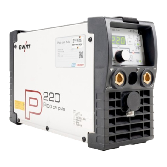
- Page 1 Operating instructions Welding machine Pico 220 cel puls Pico 220 cel puls vrd (AUS) Pico 220 cel puls vrd (RU) 099-002057-EW501 Observe additional system documents! 04.03.2019...
- Page 2 +49 2680 181-0. A list of authorised sales partners can be found at www.ewm-group.com/en/specialist-dealers. Liability relating to the operation of this equipment is restricted solely to the function of the equipment. No other form of liability, regardless of type, shall be accepted.
-
Page 3: Table Of Contents
Contents Notes on the use of these operating instructions Contents 1 Contents ..............................3 2 For your safety ............................5 Notes on the use of these operating instructions ................5 Explanation of icons ........................6 Part of the complete documentation ....................6 Safety instructions .......................... - Page 4 Display machine control software version ..................38 Resetting welding parameters to the factory settings ..............39 8 Technical data............................40 Pico 220 cel puls .......................... 40 9 Accessories ............................41 Transport systems ........................41 Remote controls and accessories ....................41 General accessories ........................
-
Page 5: For Your Safety
For your safety Notes on the use of these operating instructions For your safety Notes on the use of these operating instructions DANGER Working or operating procedures which must be closely observed to prevent imminent serious and even fatal injuries. •... -
Page 6: Explanation Of Icons
For your safety Explanation of icons Explanation of icons Symbol Description Symbol Description Indicates technical aspects which the Activate and release / Tap / Tip user must observe. Switch off machine Release Switch on machine Press and hold Switch Incorrect / Invalid Turn Numerical value –... - Page 7 For your safety Part of the complete documentation Item Documentation Power source Remote control Welding torch Complete documentation 099-002057-EW501 04.03.2019...
-
Page 8: Safety Instructions
For your safety Safety instructions Safety instructions WARNING Risk of accidents due to non-compliance with the safety instructions! Non-compliance with the safety instructions can be fatal! • Carefully read the safety instructions in this manual! • Observe the accident prevention regulations and any regional regulations! •... - Page 9 For your safety Safety instructions WARNING Explosion risk! Apparently harmless substances in closed containers may generate excessive pressure when heated. • Move containers with inflammable or explosive liquids away from the working area! • Never heat explosive liquids, dusts or gases by welding or cutting! Fire hazard! Due to the high temperatures, sparks, glowing parts and hot slag that occur during welding, there is a risk of flames.
- Page 10 For your safety Safety instructions CAUTION Smoke and gases! Smoke and gases can lead to breathing difficulties and poisoning. In addition, solvent vapour (chlorinated hydrocarbon) may be converted into poisonous phosgene due to the ultraviolet radiation of the arc! • Ensure that there is sufficient fresh air! •...
- Page 11 For your safety Safety instructions CAUTION Obligations of the operator! The respective national directives and laws must be complied with when operating the machine! • Implementation of national legislation relating to framework directive 89/391/EEC on the introduction of measures to encourage improvements in the safety and health of workers at work and associated individual guidelines.
-
Page 12: Transport And Installation
For your safety Transport and installation Transport and installation WARNING Risk of injury due to improper handling of shielding gas cylinders! Improper handling and insufficient securing of shielding gas cylinders can cause serious injuries! • Observe the instructions from the gas manufacturer and any relevant regulations concerning the use of compressed air! •... -
Page 13: Intended Use
3.3.1 Warranty For more information refer to the "Warranty registration" brochure supplied and our information regarding warranty, maintenance and testing at www.ewm-group.com! 3.3.2 Declaration of Conformity The labelled product complies with the following EC directives in terms of its design and construction: •... -
Page 14: Calibration/Validation
Intended use Documents which also apply 3.3.5 Calibration/Validation We hereby confirm that this product was tested with calibrated measuring equipment according to the applicable standards IEC/EN 60974, ISO/EN 17662, EN 50504 and complies with the permissible tolerances. Recommended calibration interval: 12 months. 099-002057-EW501 04.03.2019... -
Page 15: Machine Description - Quick Overview
Machine description – quick overview Front view Machine description – quick overview Front view Figure 4-1 Item Symbol Description Carrying strap > see 5.1.4 chapter Machine control > see 4.3 chapter Connection socket, "-" welding current • TIG: Welding current lead connection for TIG welding torch •... -
Page 16: Rear View
Machine description – quick overview Rear view Rear view Figure 4-2 Item Symbol Description Main switch, machine on/off Cooling air inlet Mains connection cable > see 5.1.7 chapter 099-002057-EW501 04.03.2019... -
Page 17: Machine Control - Operating Elements
Machine description – quick overview Machine control – Operating elements Machine control – Operating elements Figure 4-3 099-002057-EW501 04.03.2019... - Page 18 Machine description – quick overview Machine control – Operating elements Item Symbol Description Collective interference signal light For error messages, > see 7 chapter Excess temperature signal light In case of excess temperature, temperature monitors de-activate the power unit, and the excess temperature control lamp comes on.
-
Page 19: Design And Function
Design and function Transport and installation Design and function Transport and installation WARNING Risk of accident due to improper transport of machines that must not be lifted! Do not lift or suspend the machine! The machine can drop and cause injuries! The handles, straps or brackets are suitable for transport by hand only! •... -
Page 20: Adjusting The Length Of The Carrying Strap
Design and function Transport and installation 5.1.4 Adjusting the length of the carrying strap To demonstrate adjustment, lengthening the strap is shown in the figure. To shorten, the strap's loops must be inched in the opposite direction. Figure 5-1 5.1.5 Notes on the installation of welding current leads •... -
Page 21: Stray Welding Currents
Design and function Transport and installation 5.1.6 Stray welding currents WARNING Risk of injury due to stray welding currents! Stray welding currents can destroy protective earth conductors, damage machines and electronic devices and cause overheating of components, leading to fire. •... -
Page 22: Mains Configuration
Design and function MMA welding 5.1.7.1 Mains configuration The machine may be connected to: • a three-phase system with four conductors and an earthed neutral conductor • a three-phase system with three conductors of which any one can be earthed, e.g. -
Page 23: Welding Task Selection
Design and function MMA welding Item Symbol Description Electrode holder Connection socket, “-” welding current Workpiece lead or electrode holder connection Workpiece Connection socket for "+" welding current Electrode holder or workpiece lead connection • Insert cable plug of the electrode holder into either the "+" or "-" welding current connection socket and lock by turning to the right. -
Page 24: Hotstart
Design and function MMA welding Item Symbol Description Welding procedure/power-saving mode push-button --------- Selection of MMA welding procedure/electrode type setting Signal light illuminated in green = electrode type rutile Signal light illuminated in red = electrode type rutile basic Signal light illuminated in green = electrode type basic/rutile cellulose Signal light illuminated in red = electrode type cellulose... -
Page 25: Antistick
Design and function MMA welding 5.2.5 Antistick The Antistick feature prevents the electrode from annealing. Should the electrode stick despite the Arcforce feature, the machine automatically switches to the minimum current within approx. one second. This prevents the electrode from annealing. Check the welding current setting and correct for the welding task in hand. -
Page 26: Expert Menu (Mma)
Design and function TIG welding Display Setting/selection Pulse welding (average value pulses) ------- Function switched on ------- Function switched off (ex works) Pulse frequency More parameters can be set in the Expert menu > see 5.2.7 chapter. 5.2.7 Expert menu (MMA) The Expert menu has adjustable parameters stored that don’t require regular setting. -
Page 27: Tig Welding
Design and function TIG welding TIG welding 5.3.1 Shielding gas supply (shielding gas cylinder for welding machine) WARNING Risk of injury due to improper handling of shielding gas cylinders! Improper handling and insufficient securing of shielding gas cylinders can cause serious injuries! •... -
Page 28: Connecting A Tig Welding Torch With Rotating Gas Valve
Design and function TIG welding 5.3.2 Connecting a TIG welding torch with rotating gas valve Prepare welding torch according to the welding task in hand (see operating instructions for the torch). Figure 5-15 Item Symbol Description Workpiece Connection socket for "+" welding current Workpiece lead connection Output side of the pressure regulator Welding torch... -
Page 29: Arc Ignition
Design and function TIG welding 5.3.4 Arc ignition 5.3.4.1 Liftarc Figure 5-17 The arc ignites through contact with the workpiece: a) Carefully place the torch gas nozzle and tungsten electrode tip against the workpiece (lift arc current flows independent of the set main current) b) Angle the torch above the torch gas nozzle until the distance between electrode tip and workpiece is approx. -
Page 30: Expert Menu (Tig)
Design and function TIG welding Figure 5-19 Display Setting/selection Pulse welding (average value pulses) ------- Function switched on ------- Function switched off (ex works) Pulse frequency More parameters can be set in the Expert menu > see 5.3.6 chapter. 5.3.6 Expert menu (TIG) The Expert menu has adjustable parameters stored that don’t require regular setting. -
Page 31: Dirt Filter
Design and function Dirt filter Display Setting/selection Ignition current (as percentage, dependent on main current) Upslope time to main current Pulse balance Pulse current > see 5.3.5 chapter Arc length restriction > see 5.7 chapter ------- Function switched on ------- Function switched off The setting ranges for the parameter values are summarised in the Parameter overview section >... -
Page 32: Rtg1 19Pol
Design and function Power-saving mode (Standby) 5.5.2 RTG1 19POL Functions • Infinite setting of the welding current (0% to 100%) depending on the main current preselected at the welding machine 5.5.3 RTF1 19POL Functions • Infinitely adjustable welding current (0% to 100%) depending on the preselected main current on the welding machine. -
Page 33: Machine Configuration Menu
Design and function Machine configuration menu Machine configuration menu ENTER EXIT NAVIGATION Figure 5-22 Display Setting/selection Calibration The machine will be calibrated for approx 2 seconds each time it is switched on. Exit the menu Exit Machine configuration Settings for machine functions and parameter display Time-based power-saving mode<dg_ref_source_inline>Energiesparfunktion</dg_ref_source_inline>... -
Page 34: Maintenance, Care And Disposal
Maintenance, care and disposal General Maintenance, care and disposal General DANGER Risk of injury due to electrical voltage after switching off! Working on an open machine can lead to fatal injuries! Capacitors are loaded with electrical voltage during operation. Voltage remains present for up to four minutes after the mains plug is removed. -
Page 35: Maintenance Work, Intervals
A periodic test according to IEC 60974-4 "Periodic inspection and test" has to be carried out. In addition to the regulations on testing given here, the relevant local laws and regulations must also be observed. For more information refer to the "Warranty registration" brochure supplied and our information regarding warranty, maintenance and testing at www.ewm-group.com! 099-002057-EW501 04.03.2019... -
Page 36: Disposing Of Equipment
• Information about returning used equipment or about collections can be obtained from the respective municipal administration office. • In addition to this, returns are also possible throughout Europe via EWM sales partners. 099-002057-EW501 04.03.2019... -
Page 37: Rectifying Faults
Rectifying faults Checklist for rectifying faults Rectifying faults All products are subject to rigorous production checks and final checks. If, despite this, something fails to work at any time, please check the product using the following flowchart. If none of the fault rectification procedures described leads to the correct functioning of the product, please inform your authorised dealer. -
Page 38: Machine Faults (Error Messages)
Rectifying faults Machine faults (error messages) Machine faults (error messages) A welding machine error is indicated by the collective fault signal lamp (A1) lighting up and an error code (see table) being displayed in the machine control display. In the event of a machine error, the power unit shuts down. -
Page 39: Resetting Welding Parameters To The Factory Settings
Rectifying faults Resetting welding parameters to the factory settings Resetting welding parameters to the factory settings All customised welding parameters that are stored will be replaced by the factory settings. Figure 7-1 Display Setting/selection Calibration The machine will be calibrated for approx 2 seconds each time it is switched on. Initialising Keep the push-button pressed until is shown on the display. -
Page 40: Technical Data
Technical data Pico 220 cel puls Technical data Performance specifications and guarantee only in connection with original spare and replacement parts! Pico 220 cel puls Welding current (I 10 A to 220 A Welding voltage according to standard (U 20,4 V to 28,8 V 10,4 V to 18,8 V Duty cycle DC at 40°... -
Page 41: Accessories
Accessories Transport systems Accessories Performance-dependent accessories like torches, workpiece leads, electrode holders or intermediate hose packages are available from your authorised dealer. Transport systems Type Designation Item no. Trolly 35-1 Transport vehicle 090-008629-00000 Remote controls and accessories Type Designation Item no. RT1 19POL Remote control current 090-008097-00000... -
Page 42: Appendix
Appendix Parameter overview Appendix 10.1 Parameter overview 10.1.1 MMA welding Parameters/function Setting range Pulse welding Pulse frequency Hot start current (AMP%) Hot start time 20,0 Arcforce correction Pulse balance Pulse current Arc length restriction 10.1.2 TIG welding Parameters/function Setting range Pulse welding Pulse frequency - 2000... -
Page 43: Basic Parameters (Independent Of Process)
Appendix Parameter overview 10.1.3 Basic parameters (independent of process) Parameters/function Setting range Switched on Switched off Calibration Initialisation Machine configuration Exit menu Service menu Time-based power-saving mode min. Power-saving mode active 099-002057-EW501 04.03.2019... -
Page 44: Searching For A Dealer
Appendix Searching for a dealer 10.2 Searching for a dealer Sales & service partners www.ewm-group.com/en/specialist-dealers "More than 400 EWM sales partners worldwide" 099-002057-EW501 04.03.2019...
Need help?
Do you have a question about the Pico 220 cel puls and is the answer not in the manual?
Questions and answers