
Related Manuals for EWM Pico 160 cel puls


Summary of Contents for EWM Pico 160 cel puls
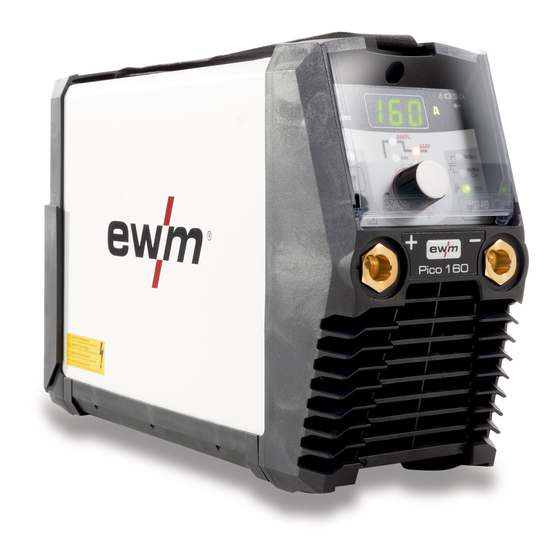
- Page 1 Operating instructions Welding machine Pico 160 cel puls Pico 160 cel puls VRD (RU) Pico 160 cel puls VRD (AUS) 099-002129-EW501 11.05.2017...
-
Page 2: General Instructions
+49 2680 181-0. A list of authorised sales partners can be found at www.ewm-group.com. Liability relating to the operation of this equipment is restricted solely to the function of the equipment. -
Page 3: Table Of Contents
Contents Notes on the use of these operating instructions Contents 1 Contents ..............................3 2 For your safety ............................5 Notes on the use of these operating instructions ................5 2.1.1 Complete documentation ....................5 Explanation of icons ........................6 General ............................ - Page 4 Dynamic power adjustment ......................32 Resetting welding parameters to the factory settings ..............33 8 Technical data............................34 Pico 160 cel puls .......................... 34 9 Accessories ............................35 Electrode holder / workpiece lead ....................35 Remote controls and accessories ....................35 TIG welding torch .........................
-
Page 5: For Your Safety
For your safety Notes on the use of these operating instructions For your safety Notes on the use of these operating instructions 2.1.1 Complete documentation These operating instructions are part of the complete documentation and valid only in combination with the "Safety instructions”! Read and observe the documents for all system components! Figure 2-1 Item... -
Page 6: Explanation Of Icons
For your safety Explanation of icons Explanation of icons Symbol Description Symbol Description Indicates technical aspects which the Activate and release/tap/tip user must observe. Switch off machine Release Switch on machine Press and keep pressed Switch Wrong Turn Numerical value – adjustable Correct Menu entry Signal light lights up in green... -
Page 7: General
For your safety General General Obligations of the operator! The respective national directives and laws must be complied with when operating the machine! • Implementation of national legislation relating to framework directive 89/391/EEC on the introduction of measures to encourage improvements in the safety and health of workers at work and associated individual guidelines. -
Page 8: Intended Use
In case of unauthorised changes, improper repairs, non-compliance with specified deadlines for "Arc Welding Equipment – Inspection and Testing during Operation", and/or prohibited modifications which have not been explicitly authorised by EWM, this declaration shall be voided. An original document of the specific declaration of conformity is included with every product. -
Page 9: Machine Description - Quick Overview
Machine description – quick overview Front view Machine description – quick overview Front view Figure 4-1 Item Symbol Description Carrying strap > see 5.1.4 chapter Machine control > see 4.3 chapter Protective cap Connection socket, "+" welding current • MMA: Electrode holder or workpiece lead connection •... -
Page 10: Rear View
Machine description – quick overview Rear view Rear view Figure 4-2 Item Symbol Description Main switch, machine on/off Cooling air inlet Mains connection cable > see 5.1.6 chapter Machine control – Operating elements The setting ranges for the parameter values are summarised in the Parameter overview section >... - Page 11 Machine description – quick overview Machine control – Operating elements Item Symbol Description Excess temperature signal light In case of excess temperature, temperature monitors de-activate the power unit, and the excess temperature control lamp comes on. Once the machine has cooled down, welding can continue without any further measures.
-
Page 12: Design And Function
Design and function Transport and installation Design and function WARNING Risk of injury from electric shock! Contact with live parts, e.g. welding current sockets, is potentially fatal! • Follow safety instructions on the opening pages of the operating instructions. • Commissioning may only be carried out by persons who have the relevant expertise of working with arc welding machines! •... -
Page 13: Ambient Conditions
Design and function Transport and installation 5.1.3 Ambient conditions T he machine must not be operated in the open air and must only be set up and operated on a suitable, stable and level base! • The operator must ensure that the ground is non-slip and level, and provide sufficient lighting for the place of work. -
Page 14: Stray Welding Currents
Design and function Transport and installation Fully unroll welding current leads, torch hose packages and intermediate hose packages. Avoid loops! Always keep leads as short as possible! Lay any excess cable lengths in meanders. Figure 5-3 5.1.5.1 Stray welding currents WARNING Risk of injury due to stray welding currents! Stray welding currents can destroy protective earth conductors, damage machines and... -
Page 15: Mains Connection
Design and function Operating the machine control 5.1.6 Mains connection DANGER Hazards caused by improper mains connection! An improper mains connection can cause injuries or damage property! • Only operate machine using a socket that has correctly fitted protective earth. •... -
Page 16: Mma Welding
Design and function MMA welding MMA welding 5.3.1 Connecting the electrode holder and workpiece lead CAUTION Risk of crushing and burns! When changing stick electrodes there is a risk of crushing and burns! • Wear appropriate and dry protective gloves. •... -
Page 17: Arcforce
Design and function MMA welding Type Electrode type Rutile Rutile-basic Basic Rutile cellulose Cellulose 5.3.3 Arcforce During the welding process, arcforce prevents the electrode sticking in the weld pool with increases in current. This makes it easier to weld large-drop melting electrode types at low current strengths with a short arc in particular. -
Page 18: Average Value Pulse Welding
Design and function MMA welding 5.3.6 Average value pulse welding Average value pulse welding means that two currents are switched periodically, a current average value (AMP), a pulse current (Ipuls), a balance ( ) and a frequency ( ) having been defined first. The predefined ampere current average value is decisive, the pulse current (Ipuls) is defined by the parameter as a percentage of the current average value (AMP). -
Page 19: Expert Menu (Mma)
Design and function MMA welding 5.3.7 Expert menu (MMA) The Expert menu has adjustable parameters stored that don’t require regular setting. The number of parameters shown may be limited, e.g. if a function is deactivated. The setting ranges for the parameter values are summarised in the Parameter overview section >... -
Page 20: Tig Welding
Design and function TIG welding TIG welding 5.4.1 Connecting a TIG welding torch with rotating gas valve Prepare welding torch according to the welding task in hand (see operating instructions for the torch). Figure 5-13 Item Symbol Description Workpiece Connection socket for "+" welding current Workpiece lead connection Output side of the pressure regulator Welding torch... -
Page 21: Pressure Regulator Connection
Design and function TIG welding 5.4.3 Pressure regulator connection Figure 5-14 Item Symbol Description Pressure regulator Shielding gas cylinder Output side of the pressure regulator Cylinder valve • Before connecting the pressure regulator to the gas cylinder, open the cylinder valve briefly to blow out any dirt. -
Page 22: Arc Ignition
Design and function TIG welding 5.4.5 Arc ignition 5.4.5.1 Liftarc Figure 5-16 The arc ignites through contact with the workpiece: a) Carefully place the torch gas nozzle and tungsten electrode tip against the workpiece (lift arc current flows independent of the set main current) b) Angle the torch above the torch gas nozzle until the distance between electrode tip and workpiece is approx. -
Page 23: Expert Menu (Tig)
Design and function TIG welding 5.4.7 Expert menu (TIG) The Expert menu has adjustable parameters stored that don’t require regular setting. The number of parameters shown may be limited, e.g. if a function is deactivated. The setting ranges for the parameter values are summarised in the Parameter overview section >... -
Page 24: Arc Length Restriction (Usp)
Design and function Arc length restriction (USP) Arc length restriction (USP) The arc length restriction function stops the welding process when an excessive arc voltage is detected (unusually high gap between electrode and workpiece). This function can be adjusted in the corresponding Expert menu, depending on the process: MMA welding >... -
Page 25: Access Control
Design and function Access control Access control The control can be locked to secure some basic parameters against unauthorised or unintentional adjustment of machine settings. The access block operates as follows: • The parameters and their settings in the machine configuration menu, Expert menu and operation sequence can only be viewed but not changed. -
Page 26: Machine Configuration Menu
Design and function Machine configuration menu Machine configuration menu Basic machine settings are defined in the machine configuration menu. ENTER NAVIGATION EXIT Figure 5-20 099-002129-EW501 11.05.2017... -
Page 27: Calibration
Design and function Machine configuration menu Display Setting/selection Calibration The machine will be calibrated for approx 2 seconds each time it is switched on. Exit the menu Exit Machine configuration Settings for machine functions and parameter display Dynamic power adjustment > see 7.4 chapter Time-based power-saving mode >... -
Page 28: Maintenance, Care And Disposal
Maintenance, care and disposal General Maintenance, care and disposal General DANGER Risk of injury due to electrical voltage after switching off! Working on an open machine can lead to fatal injuries! Capacitors are loaded with electrical voltage during operation. Voltage remains present for up to four minutes after the mains plug is removed. -
Page 29: Maintenance Work, Intervals
A periodic test according to IEC 60974-4 "Periodic inspection and test" has to be carried out. In addition to the regulations on testing given here, the relevant local laws and regulations must also be observed. For more information refer to the "Warranty registration" brochure supplied and our information regarding warranty, maintenance and testing at www.ewm-group.com! 099-002129-EW501 11.05.2017... -
Page 30: Disposing Of Equipment
In addition to this, returns are also possible throughout Europe via EWM sales partners. Meeting the requirements of RoHS We, EWM AG in Mündersbach, Germany, hereby confirm that all products which we supply to you and that are subject to the RoHS directive comply with RoHS requirements (also see applicable EC directives on the Declaration of Conformity on your machine). -
Page 31: Rectifying Faults
Rectifying faults Error messages (power source) Rectifying faults All products are subject to rigorous production checks and final checks. If, despite this, something fails to work at any time, please check the product using the following flowchart. If none of the fault rectification procedures described leads to the correct functioning of the product, please inform your authorised dealer. -
Page 32: Checklist For Rectifying Faults
Rectifying faults Checklist for rectifying faults Checklist for rectifying faults The correct machine equipment for the material and process gas in use is a fundamental requirement for perfect operation! Legend Symbol Description Fault/Cause Remedy Excess temperature signal light illuminates ... -
Page 33: Resetting Welding Parameters To The Factory Settings
Rectifying faults Resetting welding parameters to the factory settings Resetting welding parameters to the factory settings All customised welding parameters that are stored will be replaced by the factory settings. RESET Figure 7-1 Display Setting/selection Calibration The machine will be calibrated for approx 2 seconds each time it is switched on. Initialising Keep the push-button pressed until "InI"... -
Page 34: Technical Data
Technical data Pico 160 cel puls Technical data Performance specifications and guarantee only in connection with original spare and replacement parts! Pico 160 cel puls Current setting range 5 A–150 A 5 A–160 A Voltage setting range 20.2 V–26.0 V 10.2 V–16.4 V... -
Page 35: Accessories
Accessories Electrode holder / workpiece lead Accessories Electrode holder / workpiece lead Type Designation Item no. EH25 QMM 4M Electrode holder 094-005800-00000 WK16mm² 170A/60% 4m/K Workpiece lead 094-005801-00000 Remote controls and accessories Type Designation Item no. RG13 Remote control 090-008113-00000 TIG welding torch Type Designation... -
Page 36: Service Documents
Service documents Spare and replacement parts Service documents WARNING Do not carry out any unauthorised repairs or modifications! To avoid injury and equipment damage, the unit must only be repaired or modified by specialist, skilled persons! The warranty becomes null and void in the event of unauthorised interference. •... - Page 37 Service documents Spare and replacement parts Item Order number Item Type 094-015236-E0501 Carrying strap TG3-E 094-021818-E0501 Casing panel BH276,5X201,5X124,2 094-021826-00000 Insulating foil 040-001090-E0000 Operating panel assembly with E160 rotary transducer 044-004185-10015 Rotary transducer 30POS/1,5NCM 094-019308-00000 Plastic insulation for rotary KID/D23X7,3 transducer 094-021994-00000 Fibre optics LL8X6...
-
Page 38: Circuit Diagram
Service documents Circuit diagram 10.2 Circuit diagram Figure 10-2 099-002129-EW501 11.05.2017... -
Page 39: Parameter Overview - Setting Information
Appendix A Parameter overview – setting information Appendix A Parameter overview – setting information 11.1 Parameters/function Setting range MMA (MMA) Main current (AMP) Hot start current (AMP%) Hot start time (sec) 20,0 Arcforce correction Pulse frequency Pulse balance Pulse current Arc length restriction TIG (TIG) Main current AMP... -
Page 40: Overview Of Ewm Branches
Appendix B Overview of EWM branches Appendix B 12.1 Overview of EWM branches 099-002129-EW501 11.05.2017...
Need help?
Do you have a question about the Pico 160 cel puls and is the answer not in the manual?
Questions and answers