
Related Manuals for EWM Picotig 220 puls TG


Summary of Contents for EWM Picotig 220 puls TG
- Page 1 Operating instructions Welding machine Picotig 220 puls TG 099-002068-EW501 Observe additional system documents! 26.7.2023...
- Page 2 +49 2680 181-0. A list of authorised sales partners can be found at www.ewm-group.com/en/specialist-dealers. Liability relating to the operation of this equipment is restricted solely to the function of the equipment. No other form of liability, regardless of type, shall be accepted.
-
Page 3: Table Of Contents
Contents Notes on using these operating instructions Contents 1 Contents ............................3 2 For your safety ..........................7 Notes on using these operating instructions ................ 7 Explanation of icons ......................8 Safety instructions ........................ 9 Transport and installation ....................12 3 Intended use .......................... - Page 4 Checklist for rectifying faults ....................62 Dynamic power adjustment ....................64 Resetting welding parameters to the factory settings ............64 8 Technical data ..........................65 Picotig 220 puls TG ......................65 9 Accessories ..........................66 Transport system ....................... 66 19-pole remote control ....................... 66 9.2.1...
- Page 5 Contents Notes on using these operating instructions 9.2.2 Extension cable....................66 Options ..........................66 General accessories ......................66 10 Appendix ............................. 67 10.1 Parameter overview – setting ranges ................. 67 10.1.1 TIG welding ......................67 10.1.2 MMA welding ...................... 68 10.1.3 Basic parameters (independent of process) ............
- Page 6 Contents Notes on using these operating instructions 099-002068-EW501 26.7.2023...
-
Page 7: For Your Safety
For your safety Notes on using these operating instructions For your safety Notes on using these operating instructions DANGER Working or operating procedures which must be closely observed to prevent imminent serious and even fatal injuries. • Safety notes include the "DANGER" keyword in the heading with a general warning symbol. •... -
Page 8: Explanation Of Icons
For your safety Explanation of icons Explanation of icons Symbol Description Symbol Description Indicates technical aspects which the Activate and release / Tap / Tip user must observe. Switch off machine Release Switch on machine Press and hold Incorrect / Invalid Switch Correct / Valid Turn... -
Page 9: Safety Instructions
For your safety Safety instructions Safety instructions WARNING Risk of accidents due to non-compliance with the safety instructions! Non-compliance with the safety instructions can be fatal! • Carefully read the safety instructions in this manual! • Observe the accident prevention regulations and any regional regulations! •... - Page 10 For your safety Safety instructions WARNING Risk of injury due to improper clothing! During arc welding, radiation, heat and voltage are sources of risk that cannot be avoided. The user has to be equipped with the complete personal protective equipment at all times.
- Page 11 For your safety Safety instructions CAUTION Smoke and gases! Smoke and gases may lead to shortness of breath and poisoning! The ultraviolet radia- tion of the arc may also convert solvent vapours (chlorinated hydrocarbon) into poiso- nous phosgene. • Ensure sufficient fresh air! •...
-
Page 12: Transport And Installation
For your safety Transport and installation CAUTION Obligations of the operator! The respective national directives and laws must be complied with when operating the machine! • Implementation of national legislation relating to framework directive 89/391/EEC on the int- roduction of measures to encourage improvements in the safety and health of workers at work and associated individual guidelines. - Page 13 For your safety Transport and installation CAUTION Risk of accidents due to supply lines! During transport, attached supply lines (mains leads, control cables, etc.) can cause risks, e.g. by causing connected machines to tip over and injure persons! • Disconnect all supply lines before transport! Risk of tipping! There is a risk of the machine tipping over and injuring persons or being damaged itself during movement and set up.
-
Page 14: Intended Use
3.3.1 Warranty For more information refer to the "Warranty registration" brochure supplied and our information regarding warranty, maintenance and testing at www.ewm-group.com! 3.3.2 Declaration of Conformity This product corresponds in its design and construction to the EU directives listed in the decla- ration. -
Page 15: Part Of The Complete Documentation
Intended use Documents which also apply 3.3.6 Part of the complete documentation This document is part of the complete documentation and valid only in combination with all other parts of these instructions! Read and observe the operating instructions for all system components, especially the safety instructions! The illustration shows a general example of a welding system. -
Page 16: Machine Description - Quick Overview
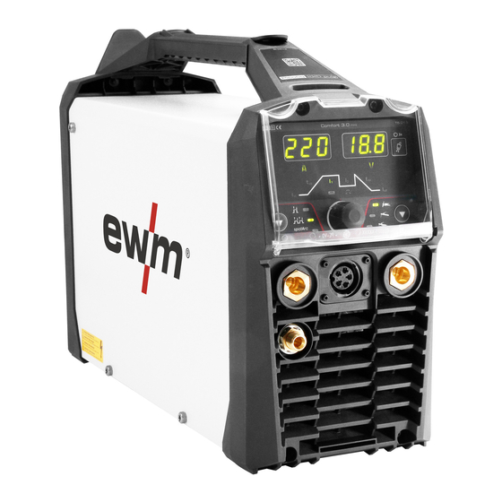
Machine description – quick overview Front view / rear view Machine description – quick overview Front view / rear view Figure 4-1 099-002068-EW501 26.7.2023... - Page 17 Machine description – quick overview Front view / rear view Item Symbol Description Transport handle with additional integrated functions • Wear part compartment > see 5.1.4 chapter • Transport belt > see 5.1.10 chapter Machine control > see 4.2 chapter Connection socket (welding torch control cable) >...
-
Page 18: Machine Control - Operating Elements
Machine description – quick overview Machine control – Operating elements Machine control – Operating elements 4.2.1 Overview of control sections For description purposes, the machine control has been divided into two sections (A, B) to ensure maximum clarity. The setting ranges for the parameter values are summarised in the parameter overview section >... -
Page 19: Control Section A
Machine description – quick overview Machine control – Operating elements 4.2.1.1 Control section A Figure 4-3 Item Symbol Description TIG ignition type signal light Signal light on: Lift arc ignition active/HF start off. You can switch the ignition type in the Expert menu (TIG) >... -
Page 20: Control Section B
Machine description – quick overview Machine control – Operating elements 4.2.1.2 Control section B Figure 4-4 Item Symbol Description Signal light for main current Signal light for up-slope time Signal light for start current Signal light for Arcforce (welding characteristics) > see 5.3.4 chapter Signal light, pulse welding >... -
Page 21: Operating The Machine Control
Machine description – quick overview Machine control – Operating elements 4.2.2 Operating the machine control 4.2.2.1 Main screen After switching on the machine or finishing a setting, the machine control changes to the main screen. This means that the previously selected settings are accepted (if necessary, indicated by signal lights) and the nominal value of the current (A) is shown in the welding data display on the left. -
Page 22: Design And Function
Design and function Transport and installation Design and function WARNING Risk of injury from electrical voltage! Contact with live parts, e.g. power connections, can be fatal! • Observe the safety information on the first pages of the operating instructions! • Commissioning must be carried out by persons who are specifically trained in handling power sources! •... -
Page 23: Ambient Conditions
Design and function Transport and installation 5.1.1 Ambient conditions The machine must not be operated in the open air and must only be set up and operated on a suitable, stable and level base! • The operator must ensure that the ground is non-slip and level, and provide sufficient lighting for the place of work. -
Page 24: Transport Belt
Design and function Transport and installation 5.1.4 Transport belt 5.1.4.1 Adjusting the length of the carrying strap Figure 5-2 5.1.5 Dirt filter These accessory components can be retrofitted as an option > see 9 chapter. When using a dirt filter, the cooling air throughput is reduced and the duty cycle of the machine is reduced as a result. - Page 25 Design and function Transport and installation • Use an individual welding lead to the workpiece for each welding machine! Figure 5-4 • Fully unroll welding current leads, torch hose packages and intermediate hose packages. Avoid loops! • Always keep leads as short as possible! Lay any excess cable lengths in meanders.
-
Page 26: Stray Welding Currents
Design and function Transport and installation 5.1.7 Stray welding currents WARNING Risk of injury due to stray welding currents! Stray welding currents can destroy protective earth conductors, damage machines and electronic devices and cause overheating of components, leading to fire. •... -
Page 27: Mains Connection
Design and function Transport and installation 5.1.8 Mains connection DANGER Hazards caused by improper mains connection! An improper mains connection can cause injuries or damage property! • The connection (mains plug or cable), the repair or voltage adjustment of the device must be carried out by a qualified electrician in accordance with the respective local laws or nati- onal regulations! •... -
Page 28: Protective Flap, Welding Machine Control
Design and function Transport and installation 5.1.9 Protective flap, welding machine control Figure 5-8 • Open the protective cap. • Apply slight pressure to the left and/or right connecting bridge (illustration) until the protective cap can be removed. 5.1.10 Wear part compartment The transport handles in this machine series have a wear part compartment for stowing typical wear parts, such as gas nozzles and electrodes. -
Page 29: Tig Welding
Design and function TIG welding TIG welding 5.2.1 Welding torch and workpiece line connection Prepare welding torch according to the welding task in hand (see operating instructions for the torch). Figure 5-10 Item Symbol Description Workpiece Connection socket for "+" welding current Workpiece lead connection Welding torch “-”... -
Page 30: Shielding Gas Supply (Shielding Gas Cylinder For Welding Machine)
Design and function TIG welding 5.2.2 Shielding gas supply (shielding gas cylinder for welding machine) WARNING Risk of injury due to improper handling of shielding gas cylinders! Improper handling and insufficient securing of shielding gas cylinders can cause seri- ous injuries! •... -
Page 31: Shielding Gas Hose Connection
Design and function TIG welding 5.2.2.2 Shielding gas hose connection Figure 5-13 Item Symbol Description Shielding gas cylinder Connection thread - G¼" Shielding gas connection (inlet) • Screw the gas hose connection nipple onto the G¼" connection nipple. 5.2.2.3 Setting the shielding gas volume (gas test)/rinse hose package •... -
Page 32: Setting Welding Procedure
Design and function TIG welding 5.2.3 Setting welding procedure Figure 5-14 Setting the tungsten electrode diameter presets the ignition energy and minimum current limit opti- mally. Smaller electrode diameters require less ignition energy than larger electrode diameters. With the selection of the electrode diameter, a minimum current limit is set that in turn affects the start, main and secondary currents. -
Page 33: Arc Ignition
Design and function TIG welding 5.2.4 Arc ignition 5.2.4.1 HF ignition Figure 5-16 The arc is started without contact using high-voltage ignition pulses: a) Position the welding torch in the welding position above the workpiece (distance between the electrode tip and the workpiece approx. 2-3 mm). b) Press the torch trigger (high-voltage ignition pulses start the arc). -
Page 34: Operating Modes (Functional Sequences)
Design and function TIG welding 5.2.5 Operating modes (functional sequences) 5.2.5.1 Explanation of symbols Symbol Meaning Press torch trigger 1 Release torch trigger 1 Current Time Gas pre-flow Start current Start time Up-slope time Spot time Main current (minimum to maximum current) Secondary current Pulse current (average value pulsing) Balance (average value pulsing) -
Page 35: Non-Latched Mode
Design and function TIG welding 5.2.5.2 Non-latched mode Sequence Figure 5-18 1st cycle: • Press and hold torch trigger 1. • The gas pre-flow time expires (shielding gas flows). • The arc is ignited (HF ignition). • The start current flows for the start time •... -
Page 36: Latched Mode
Design and function TIG welding 5.2.5.3 Latched mode Sequence Figure 5-19 1st cycle • Press the torch trigger 1 • The gas pre-flow time expires (shielding gas flows). • The arc is ignited (HF ignition). • The start current flows as long as the torch trigger is held, but at least for the start time 2nd cycle •... -
Page 37: Spotarc
Design and function TIG welding 5.2.5.4 spotArc This process is suitable for tack welding or joint welding of metal sheets made from steel and CrNi alloys up to a thickness of approximately 2.5 mm. Metal sheets of different thicknesses can also be welded on top of one another. -
Page 38: Spotmatic
Design and function TIG welding 5.2.5.5 spotmatic In contrast to the spotArc operating mode, the arc is not started by pressing the torch trigger as in the conventional method, but by briefly placing the tungsten electrode on the workpiece. The torch trig- ger is used to enable the welding process. -
Page 39: Pulse Welding
Design and function TIG welding 5.2.6 Pulse welding 5.2.6.1 Average value pulse welding A special feature with average value pulses is that the power source will always maintain the preset average value. This makes this method especially suitable for welding according to welding procedure specifications. -
Page 40: Welding Torch (Operating Variants)
Design and function TIG welding 5.2.7 Welding torch (operating variants) 5.2.7.1 Welding torch mode The operating elements (torch triggers or rockers) and their function can be individually adjusted using different torch modes. Up to four modes are available to the user. The tables for the corresponding torch types describe the functional options. -
Page 41: Tapping Function (Tap Torch Trigger)
Design and function TIG welding TIG function torch, Retox XQ Figure 5-29 Function Operation Mode Welding current On / Off BRT 1 Secondary current Secondary current BRT 2 Increase welding current (up/down speed) Decrease welding current (up/down speed) DOWN Welding current On / Off BRT 1 Secondary current Secondary current... -
Page 42: Response
Design and function TIG welding 5.2.8.1 Response This function controls the responsiveness of the welding current during the main current phase. The user can choose between linear and logarithmic responsiveness. The logarithmic setting is particularly suitable for welding with low current, e.g., for thin panels as the logarithmic responsiveness enables better control of the welding current. -
Page 43: Start/Stop Operation
Design and function TIG welding 5.2.8.3 Start/stop operation Start/stop operation “ ” can be enabled or disabled in the machine configuration menu > see 5.7 chapter. Enabled start/stop operation The foot-operated remote control is no longer used to specify the welding current, but rather starts or ends the welding process (see torch trigger). -
Page 44: Mma Welding
Design and function MMA welding MMA welding 5.3.1 Connecting the electrode holder and workpiece lead CAUTION Risk of crushing and burns! When changing stick electrodes there is a risk of crushing and burns! • Wear appropriate and dry protective gloves. •... -
Page 45: Hotstart Current
Design and function MMA welding 5.3.3.1 Hotstart current Figure 5-36 5.3.3.2 Hotstart time The hot start times can be set in the Expert menu > see 5.3.8 chapter. 5.3.4 Arcforce During the welding process, arcforce prevents the electrode sticking in the weld pool with increases in current. -
Page 46: Pulse Welding
Design and function MMA welding 5.3.6 Pulse welding 5.3.6.1 Average value pulse welding Average value pulse welding means that two currents are switched periodically, a current average value (AMP), a pulse current (Ipuls), a balance ( ) and a frequency ( ) having been defined first. -
Page 47: Remote Control
Design and function Remote control Display Setting/selection Arc length restriction > see 5.3.7 chapter ------- Function switched on ------- Function switched off Remote control The remote controls are operated on the 19-pole remote control connection socket (analogue). 5.4.1 RTF1 19POL Functions •... -
Page 48: Access Control
Design and function Access control Access control The machine control can be locked to prevent unauthorised or accidental adjustments. The access lock has the following effect: • The parameters and their settings in the machine configuration menu, expert menu and the function sequence can only be viewed but not changed. - Page 49 Design and function Machine configuration menu Display Setting/selection Exit the menu Exit Power source menu Switch ignition mode ------- HF ignition ------- Liftarc Re-ignition after arc interruption > see 5.2.4.3 chapter ------- Function switched off or time setting Minimum current limit (TIG) > see 5.2.3 chapter Depending on the set tungsten electrode diameter ------- Function disabled ------- Function enabled (ex works)
- Page 50 Design and function Machine configuration menu Display Setting/selection Up/down speed > see 5.2.7.3 chapter Increase value > rapid current change Decrease value > slow current change Current jump > see 5.2.7.4 chapter Current jump setting in ampere Remote control menu Responsiveness >...
-
Page 51: Maintenance, Care And Disposal
Maintenance, care and disposal General Maintenance, care and disposal General DANGER Risk of injury due to electrical voltage after switching off! Working on an open machine can lead to fatal injuries! Capacitors are loaded with electrical voltage during operation. Voltage remains present for up to four minutes after the mains plug is removed. -
Page 52: Maintenance Work, Intervals
A periodic test according to IEC 60974-4 "Periodic inspection and test" has to be carried out. In addition to the regulations on testing given here, the relevant local laws and regulations must also be observed. For more information refer to the "Warranty registration" brochure supplied and our information regarding warranty, maintenance and testing at www.ewm-group.com! 099-002068-EW501 26.7.2023... -
Page 53: Disposing Of Equipment
Information on returning used equipment or collections can be obtained from the respective municipal administration office. Devices can also be returned to EWM sales partners across Europe. Further information on the topic of the disposal of electrical and electronic equipment can be found on our website at: https://www.ewm-group.com/de/nachhaltigkeit.html. -
Page 54: Rectifying Faults
Rectifying faults Software version of the machine control Rectifying faults All products are subject to rigorous production checks and final checks. If, despite this, something fails to work at any time, please check the product using the following flowchart. If none of the fault rectification procedures described leads to the correct functioning of the product, please inform your authorised dea- ler. - Page 55 Rectifying faults Error messages (power source) Error 6: Mains undervoltage Category A Mains voltage is too low. Check the mains voltages and compare them with the connection voltages of the power source. Error 7: Low coolant level Category B ...
- Page 56 Rectifying faults Error messages (power source) Error 16: Pilot arc power source - collective error Category A The external emergency stop circuit has been interrupted. Check the emergency stop circuit and eliminate the cause of the error. The emergency stop circuit of the power source has been activated (internally configurable). Deactivate the emergency stop circuit.
- Page 57 Rectifying faults Error messages (power source) Error 20: Low coolant level Category B Low flow rate. Fill with coolant. Check coolant flow - remove kinks in the hose package. Adjust the flow threshold Clean the cooler. ...
- Page 58 Rectifying faults Error messages (power source) Error 26: Excess pilot arc module temperature Category A The power source is overheating. Allow the switched-on machine to cool. Fan is blocked, dirty or faulty. Check the fan and clean or replace. ...
- Page 59 Rectifying faults Error messages (power source) Error 40: Electronics error Error I>0 Request service. Error 47: Radio link (BT) Category B Connection error between welding machine and peripheral unit. Note the documentation for the data interface with radio transmission. ...
- Page 60 Rectifying faults Error messages (power source) Error 56: Mains phase failure One phase of the mains voltage has failed. Check the mains connection, mains plug and mains fuses. Error 57: Slave tacho error Category B Fault in the wire feeder (slave drive). Check the connections (connectors, lines).
-
Page 61: Warnings
Rectifying faults Warnings Warnings Depending on the display options of the machine display, a warning message is displayed as follows: Display type - machine control Display Graphic display two 7-segment displays one 7-segment display The cause of the warning is indicated by a corresponding warning number (see table). •... -
Page 62: Checklist For Rectifying Faults
Rectifying faults Checklist for rectifying faults Warning Potential cause / remedy 24 Coolant flow warning Check coolant supply. Check coolant level and top up if necessary. Check flow and switching thresholds. 25 Flow 2 reserved 26 Flow 3 reserved 27 Flow 4 reserved 28 Wire stock warning Check wire feeding. - Page 63 Rectifying faults Checklist for rectifying faults Functional errors Several parameters cannot be set (machines with access block) Entry level is blocked, disable access lock > see 5.6 chapter All machine control signal lights are illuminated after switching on ...
-
Page 64: Dynamic Power Adjustment
Rectifying faults Dynamic power adjustment Dynamic power adjustment This requires use of the appropriate mains fuse. Observe mains fuse specification > see 8 chapter! This function enables aligning the machine to the mains connection fusing to avoid continuous tripping of the mains fuse. -
Page 65: Technical Data
Technical data Picotig 220 puls TG Technical data Performance specifications and guarantee only in connection with original spare and replacement parts! Picotig 220 puls TG Welding current (I 5 A to 220 A 5 A to 190 A Welding voltage according to standard (U... -
Page 66: Accessories
Accessories Transport system Accessories Performance-dependent accessories like torches, workpiece leads, electrode holders or intermediate hose packages are available from your authorised dealer. Transport system Type Designation Item no. Trolly 35-1 Transport vehicle 090-008629-00000 19-pole remote control Type Designation Item no. RT1 19POL Remote control current 090-008097-00000... -
Page 67: Appendix
Appendix Parameter overview – setting ranges Appendix 10.1 Parameter overview – setting ranges 10.1.1 TIG welding Parameter / function Setting range Gas pre-flow time Start current Start time Up-slope time Main current Slope time (main current to secondary current) Secondary current Slope time (secondary current to main current) Down-slope time End current... -
Page 68: Mma Welding
Appendix Parameter overview – setting ranges 10.1.2 MMA welding Parameter / function Setting range Hot start current Hot start time 20,0 Main current Pulse welding Pulse frequency Pulse balance Pulse current Arcforce correction 10.1.3 Basic parameters (independent of process) Parameter / function Setting range Switching the ignition mode Time-based energy-saving function... -
Page 69: Searching For A Dealer
Appendix Searching for a dealer 10.2 Searching for a dealer Sales & service partners www.ewm-group.com/en/specialist-dealers "More than 400 EWM sales partners worldwide" 099-002068-EW501 26.7.2023...
Need help?
Do you have a question about the Picotig 220 puls TG and is the answer not in the manual?
Questions and answers