
Related Manuals for EWM Pico 160


Summary of Contents for EWM Pico 160
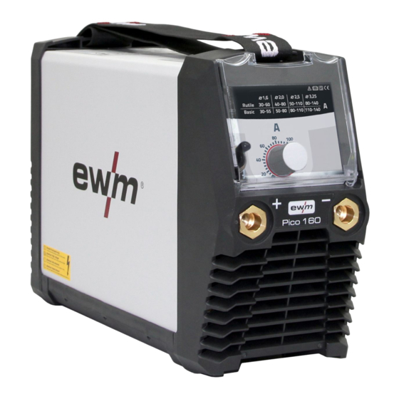
- Page 1 Operating instructions Welding machine Pico 160 Pico 160 VRD AUS 099-002128-EW501 Observe additional system documents! 26.01.2022...
- Page 2 +49 2680 181-0. A list of authorised sales partners can be found at www.ewm-group.com/en/specialist-dealers. Liability relating to the operation of this equipment is restricted solely to the function of the equipment. No other form of liability, regardless of type, shall be accepted.
-
Page 3: Table Of Contents
Monthly maintenance tasks .................. 29 6.2.3 Annual test (inspection and testing during operation) .......... 29 Disposing of equipment ....................... 30 7 Rectifying faults ........................... 31 Machine faults (error messages) ..................31 8 Technical data ..........................32 Pico 160 ..........................32 099-002128-EW501 26.01.2022... - Page 4 Contents Notes on using these operating instructions 9 Accessories ..........................33 Electrode holder / workpiece lead ..................33 TIG welding torch ......................... 33 General accessories ......................33 Options ..........................33 10 Service documents........................34 10.1 Spare and replacement parts ....................34 10.2 Circuit diagram ........................
- Page 5 Contents Notes on using these operating instructions 099-002128-EW501 26.01.2022...
-
Page 6: For Your Safety
For your safety Notes on using these operating instructions For your safety Notes on using these operating instructions DANGER Working or operating procedures which must be closely observed to prevent imminent serious and even fatal injuries. • Safety notes include the "DANGER" keyword in the heading with a general warning symbol. •... -
Page 7: Explanation Of Icons
For your safety Explanation of icons Explanation of icons Symbol Description Symbol Description Indicates technical aspects which the u- Activate and release / Tap / Tip ser must observe. Switch off machine Release Switch on machine Press and hold Switch Incorrect / Invalid Turn Correct / Valid... -
Page 8: Safety Instructions
For your safety Safety instructions Safety instructions WARNING Risk of accidents due to non-compliance with the safety instructions! Non-compliance with the safety instructions can be fatal! • Carefully read the safety instructions in this manual! • Observe the accident prevention regulations and any regional regulations! •... - Page 9 For your safety Safety instructions WARNING Risk of injury due to improper clothing! During arc welding, radiation, heat and voltage are sources of risk that cannot be avoided. The user has to be equipped with the complete personal protective equipment at all times.
- Page 10 For your safety Safety instructions CAUTION Smoke and gases! Smoke and gases can lead to breathing difficulties and poisoning. In addition, solvent vapour (chlorinated hydrocarbon) may be converted into poisonous phosgene due to the ultraviolet radiation of the arc! • Ensure that there is sufficient fresh air! •...
-
Page 11: Transport And Installation
For your safety Transport and installation CAUTION Obligations of the operator! The respective national directives and laws must be complied with when operating the machine! • Implementation of national legislation relating to framework directive 89/391/EEC on the int- roduction of measures to encourage improvements in the safety and health of workers at work and associated individual guidelines. - Page 12 For your safety Transport and installation CAUTION Risk of accidents due to supply lines! During transport, attached supply lines (mains leads, control cables, etc.) can cause risks, e.g. by causing connected machines to tip over and injure persons! • Disconnect all supply lines before transport! Risk of tipping! There is a risk of the machine tipping over and injuring persons or being damaged itself during movement and set up.
-
Page 13: Intended Use
Intended use Applications Intended use WARNING Hazards due to improper usage! The machine has been constructed to the state of the art and any regulations and stand- ards applicable for use in industry and trade. It may only be used for the welding proce- dures indicated at the rating plate. -
Page 14: Documents Which Also Apply
3.2.1 Warranty For more information refer to the "Warranty registration" brochure supplied and our information regarding warranty, maintenance and testing at www.ewm-group.com! 3.2.2 Declaration of Conformity This product corresponds in its design and construction to the EU directives listed in the decla- ration. -
Page 15: Machine Description - Quick Overview
Machine description – quick overview Front view Machine description – quick overview Front view Figure 4-1 Item Symbol Description Carrying strap > see 5.1.4.1 chapter Machine control > see 4.3 chapter Protective cap Connection socket, "+" welding current • MMA: Electrode holder or workpiece lead connection •... -
Page 16: Rear View
Machine description – quick overview Rear view Rear view Figure 4-2 Item Symbol Description Main Switch Switching the machine on or off. Cooling air inlet Mains connection cable > see 5.1.7 chapter 099-002128-EW501 26.01.2022... -
Page 17: Machine Control - Operating Elements
Machine description – quick overview Machine control – Operating elements Machine control – Operating elements Figure 4-3 Item Symbol Description Excess temperature signal light In case of excess temperature, temperature monitors de-activate the power unit, and the excess temperature control lamp comes on. Once the machine has cooled down, welding can continue without any further measures. -
Page 18: Design And Function
Design and function Transport and installation Design and function WARNING Risk of injury from electrical voltage! Contact with live parts, e.g. power connections, can be fatal! • Observe the safety information on the first pages of the operating instructions! • Commissioning must be carried out by persons who are specifically trained in handling power sources! •... -
Page 19: Ambient Conditions
Design and function Transport and installation 5.1.3 Ambient conditions The machine must not be operated in the open air and must only be set up and operated on a suitable, stable and level base! • The operator must ensure that the ground is non-slip and level, and provide sufficient lighting for the place of work. -
Page 20: Notes On The Installation Of Welding Current Leads
Design and function Transport and installation 5.1.5 Notes on the installation of welding current leads • Use an individual welding lead to the workpiece for each welding machine! Figure 5-2 • Fully unroll welding current leads, torch hose packages and intermediate hose packages. Avoid loops! •... -
Page 21: Stray Welding Currents
Design and function Transport and installation 5.1.6 Stray welding currents WARNING Risk of injury due to stray welding currents! Stray welding currents can destroy protective earth conductors, damage machines and electronic devices and cause overheating of components, leading to fire. •... -
Page 22: Mains Connection
Design and function Transport and installation 5.1.7 Mains connection DANGER Hazards caused by improper mains connection! An improper mains connection can cause injuries or damage property! • The connection (mains plug or cable), the repair or voltage adjustment of the device must be carried out by a qualified electrician in accordance with the respective local laws or nati- onal regulations! •... -
Page 23: Mma Welding
Design and function MMA welding MMA welding 5.2.1 Connecting the electrode holder and workpiece lead CAUTION Risk of crushing and burns! When changing stick electrodes there is a risk of crushing and burns! • Wear appropriate and dry protective gloves. •... -
Page 24: Welding Task Selection
Design and function MMA welding 5.2.2 Welding task selection Figure 5-7 Type Electrode type Rutile Rutile Basic Basic 5.2.3 Hotstart The function hot start ensures a secure igniting of the arc and a sufficient heating to the still cold parent metal at the beginning of the welding process. -
Page 25: Tig Welding
Design and function TIG welding TIG welding 5.3.1 Connecting a TIG welding torch with rotating gas valve Prepare welding torch according to the welding task in hand (see operating instructions for the torch). Figure 5-10 Item Symbol Description Workpiece Connection socket for "+" welding current Workpiece lead connection Output side of the pressure regulator Welding torch... -
Page 26: Pressure Regulator Connection
Design and function TIG welding 5.3.2.1 Pressure regulator connection Figure 5-11 Item Symbol Description Pressure regulator Output side of the pressure regulator Shielding gas cylinder Cylinder valve • Before connecting the pressure regulator to the gas cylinder, open the cylinder valve briefly to blow out any dirt. -
Page 27: Arc Ignition
Design and function Voltage reducing device 5.3.4 Arc ignition 5.3.4.1 Liftarc Figure 5-13 The arc ignites through contact with the workpiece: a) Carefully place the torch gas nozzle and tungsten electrode tip against the workpiece (lift arc current flows independent of the set main current) b) Angle the torch above the torch gas nozzle until the distance between electrode tip and workpiece is approx. -
Page 28: Maintenance, Care And Disposal
Maintenance, care and disposal General Maintenance, care and disposal General DANGER Risk of injury due to electrical voltage after switching off! Working on an open machine can lead to fatal injuries! Capacitors are loaded with electrical voltage during operation. Voltage remains present for up to four minutes after the mains plug is removed. -
Page 29: Maintenance Work, Intervals
A periodic test according to IEC 60974-4 "Periodic inspection and test" has to be carried out. In addition to the regulations on testing given here, the relevant local laws and regulations must also be observed. For more information refer to the "Warranty registration" brochure supplied and our information regarding warranty, maintenance and testing at www.ewm-group.com! 099-002128-EW501 26.01.2022... -
Page 30: Disposing Of Equipment
Information on returning used equipment or collections can be obtained from the respective municipal administration office. Devices can also be returned to EWM sales partners across Europe. Further information on the topic of the disposal of electrical and electronic equipment can be found on our website at: https://www.ewm-group.com/de/nachhaltigkeit.html. -
Page 31: Rectifying Faults
Rectifying faults Machine faults (error messages) Rectifying faults All products are subject to rigorous production checks and final checks. If, despite this, something fails to work at any time, please check the product using the following flowchart. If none of the fault rectification procedures described leads to the correct functioning of the product, please inform your authorised dea- ler. -
Page 32: Technical Data
Technical data Pico 160 Technical data Performance specifications and guarantee only in connection with original spare and replacement parts! Pico 160 Welding current (I 10 A to 150 A 10 A to 160 A Welding voltage according to standard (U... -
Page 33: Accessories
SKGS 16A 250V CEE7/7, DIN Safety plug 094-001756-00000 49440/441 ADAP CEE16/SCHUKO Earth contact coupling/CEE16A plug 092-000812-00000 Options Type Designation Item no. ON Filter Pico160 Air inlet dirt filter, retrofit option 092-003206-00000 ON Handle Pico 160 Grip, retrofit option 092-003205-00000 099-002128-EW501 26.01.2022... -
Page 34: Service Documents
Service documents Spare and replacement parts Service documents WARNING Do not carry out any unauthorised repairs or modifications! To avoid injury and equipment damage, the unit must only be repaired or modified by specialist, skilled persons! The warranty becomes null and void in the event of unauthorised interference. •... - Page 35 Service documents Spare and replacement parts Position Order number Designation Type 1 094-015236-E0501 Carrying strap TG3-E 2 094-021818-E0501 Casing BG BH276,5X201,5X124,2 3 094-021826-00000 Insulating paper 4 040-001129-E0000 Printed circuit board (PCB) - replace- E161 ment 5 094-021994-00000 Light guide LL8X6 6 094-023159-00001 Plastic insulation 7 094-022197-00500 Adhesive film KLF-E 1.06...
-
Page 36: Circuit Diagram
Service documents Circuit diagram 10.2 Circuit diagram Figure 10-2 099-002128-EW501 26.01.2022... -
Page 37: Appendix
Appendix Searching for a dealer Appendix 11.1 Searching for a dealer Sales & service partners www.ewm-group.com/en/specialist-dealers "More than 400 EWM sales partners worldwide" 099-002128-EW501 26.01.2022...
Need help?
Do you have a question about the Pico 160 and is the answer not in the manual?
Questions and answers