EWM Pico 300 cel Operating Instructions Manual
Hide thumbs
Also See for Pico 300 cel:
- Operating instructions manual (52 pages) ,
- Operating instructions manual (42 pages) ,
- Operating instructions manual (41 pages)

Related Manuals for EWM Pico 300 cel


Summary of Contents for EWM Pico 300 cel
- Page 1 Operating instructions Welding machines for MMA welding Pico 300 cel Pico 300 cel VRD Pico 300 cel SVRD Pico 300 cel pws Pico 300 cel pws VRD Pico 300 cel pws SVRD 099-002032-EW501 29.04.2010...
-
Page 2: General Instructions
© EWM HIGHTEC WELDING GmbH · Dr. Günter-Henle-Str. 8 · D-56271 Mündersbach, Germany The copyright to this document remains the property of the manufacturer. -
Page 3: Table Of Contents
MMA welding ..........................23 5.6.1 Connecting the electrode holder and workpiece lead ..........23 5.6.1.1 Pico 300 cel....................23 5.6.1.2 Pico 300 cel pws ................... 24 5.6.2 Selecting MMA welding ....................26 5.6.2.1 Arcforce (welding characteristics) ..............26 5.6.3 Hotstart current and Hotstart time ................27 5.6.4... - Page 4 8 Technical data............................42 Pico 300 cel..........................42 9 Accessories, options ...........................43 Welding torch, electrode holder and workpiece lead ..............43 Remote controls and accessories....................43 9.2.1 Pico 300 cel pws......................43 Options ............................43 General accessories ........................43 10 Appendix A............................44 10.1 Overview of EWM branches......................44 099-002032-EW501...
-
Page 5: Safety Instructions
Safety instructions Notes on the use of these operating instructions Safety instructions Safety instructions Notes on the use of these operating instructions DANGER Working or operating procedures which must be closely observed to prevent imminent serious and even fatal injuries. •... - Page 6 Safety instructions Notes on the use of these operating instructions Instructions and lists detailing step-by-step actions for given situations can be recognised via bullet points, e.g.: • Insert the welding current lead socket into the relevant socket and lock. Symbol Description Press Do not press...
-
Page 7: General
Safety instructions General General DANGER Electromagnetic fields! The power source may cause electrical or electromagnetic fields to be produced which could affect the correct functioning of electronic equipment such as IT or CNC devices, telecommunication lines, power cables, signal lines and pacemakers. •... - Page 8 Safety instructions General WARNING Smoke and gases! Smoke and gases can lead to breathing difficulties and poisoning. In addition, solvent vapour (chlorinated hydrocarbon) may be converted into poisonous phosgene due to the ultraviolet radiation of the arc! • Ensure that there is sufficient fresh air! •...
- Page 9 Safety instructions General CAUTION Obligations of the operator! The respective national directives and laws must be observed for operation of the machine! • National implementation of the framework directive (89/391/EWG), as well as the associated individual directives. • In particular, directive (89/655/EWG), on the minimum regulations for safety and health protection when staff members use equipment during work.
-
Page 10: Transport And Installation
Safety instructions Transport and installation Transport and installation WARNING Incorrect handling of shielding gas cylinders! Incorrect handling of shielding gas cylinders can result in serious and even fatal injury. • Observe the instructions from the gas manufacturer and in any relevant regulations concerning the use of compressed air! •... -
Page 11: Ambient Conditions
Safety instructions Ambient conditions Ambient conditions CAUTION Installation site! The machine must not be operated in the open air and must only be set up and operated on a suitable, stable and level base! • The operator must ensure that the ground is non-slip and level, and provide sufficient lighting for the place of work. -
Page 12: Intended Use
Intended use Applications Intended use This machine has been manufactured according to the latest developments in technology and current regulations and standards. It must only be operated in line with the instructions on correct usage. WARNING Hazards due to improper usage! Hazards may arise for persons, animals and material objects if the equipment is not used correctly. -
Page 13: Documents Which Also Apply
Intended use Documents which also apply Documents which also apply 3.3.1 Warranty NOTE For further information, please see the accompanying supplementary sheets "Machine and Company Data, Maintenance and Testing, Warranty"! 3.3.2 Declaration of Conformity The designated machine conforms to EC Directives and standards in terms of its design and construction: •... -
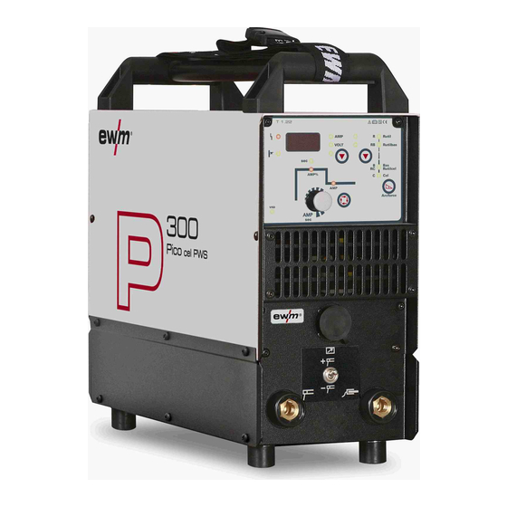
Page 14: Machine Description - Quick Overview
Machine description – quick overview Pico 300 cel Machine description – quick overview Pico 300 cel 4.1.1 Front view Figure 4-1 099-002032-EW501 29.04.2010... - Page 15 Machine description – quick overview Pico 300 cel Item Symbol Description Carrying strap Transport bar Carrying handle Machine control See Machine control – operating elements chapter Cooling air inlet Connection socket, "+" welding current • TIG: Connection for workpiece lead •...
-
Page 16: Rear View
Machine description – quick overview Pico 300 cel 4.1.2 Rear view Figure 4-2 099-002032-EW501 29.04.2010... - Page 17 Machine description – quick overview Pico 300 cel Item Symbol Description Main switch, machine on/off Mains connection cable Cooling air outlet Fuse Solenoid switch pole reversal fuse Fuse Solenoid switch pole reversal fuse 099-002032-EW501 29.04.2010...
-
Page 18: Machine Control - Operating Elements
Machine description – quick overview Machine control – Operating elements Machine control – Operating elements Figure 4-3 099-002032-EW501 29.04.2010... - Page 19 Machine description – quick overview Machine control – Operating elements Item Symbol Description Collective interference signal light For error messages, see the "Rectifying faults" chapter Excess temperature signal light In case of excess temperature, temperature monitors de-activate the power unit, and the excess temperature control lamp comes on.
-
Page 20: Design And Function
Design and function General Design and function General DANGER Risk of injury from electric shock! Contact with live parts, e.g. welding current sockets, is potentially fatal! • Follow safety instructions on the opening pages of the operating instructions. • Commissioning may only be carried out by persons who have the relevant expertise of working with arc welding machines! •... -
Page 21: Transport And Installation
Design and function Transport and installation Transport and installation CAUTION Installation site! The machine must not be operated in the open air and must only be set up and operated on a suitable, stable and level base! • The operator must ensure that the ground is non-slip and level, and provide sufficient lighting for the place of work. -
Page 22: Mains Connection
Design and function Mains connection Mains connection DANGER Hazard caused by improper mains connection! An improper mains connection can cause injuries or damage property! • Only use machine with a plug socket that has a correctly fitted protective conductor. • If a mains plug must be fitted, this may only be carried out by an electrician in accordance with the relevant national provisions or regulations (any phase sequence for three-phase machines)! -
Page 23: Mma Welding
NOTE Polarity depends on the instructions from the electrode manufacturer given on the electrode packaging. 5.6.1 Connecting the electrode holder and workpiece lead 5.6.1.1 Pico 300 cel Figure 5-3 Item Symbol Description Electrode holder Connection socket for "+" welding current... -
Page 24: Pico 300 Cel Pws
Design and function MMA welding 5.6.1.2 Pico 300 cel pws NOTE The pole reversal changeover switch allows the welding current polarity (+/-) to be + / - changed without unplugging the electrode holder or workpiece leads. Changeover can also be carried out using a suitable remote control (PWS). The polarity cannot be... - Page 25 Design and function MMA welding Item Symbol Description Electrode holder Connection socket, electrode holder The welding current polarity (“+” or “-”) are based on the setting of the “Welding current polarity changeover switch”. Workpiece Connection socket, workpiece lead The welding current polarity (“+” or “-”) are based on the setting of the “Welding current polarity changeover switch".
-
Page 26: Selecting Mma Welding
Design and function MMA welding 5.6.2 Selecting MMA welding Operating Action Result element Select MMA welding process signal light lights up in green Set welding current 5.6.2.1 Arcforce (welding characteristics) During the welding process, arcforce prevents the electrode sticking in the weld pool with increases in current. -
Page 27: Hotstart Current And Hotstart Time
Design and function MMA welding 5.6.3 Hotstart current and Hotstart time The hotstart device uses an increased ignition current to improve arc ignition. The parameters for the hotstart current and time can be adjusted individually. When the stick electrode has been struck, the arc ignites at the adjusted hotstart current AMP% (factory setting: 120 % of main current) and welds at this current until the hotstart time in seconds has elapsed (factory setting: 1 second). -
Page 28: Antistick
Design and function MMA welding 5.6.4 Antistick Anti-stick prevents the electrode from annealing. If the electrode sticks in spite of the Arcforce device, the machine automatically switches over to the minimum current within about 1 second to prevent the electrode from overheating. -
Page 29: Tig Welding
Design and function TIG welding TIG welding 5.7.1 Shielding gas supply (shielding gas cylinder for welding machine) WARNING Incorrect handling of shielding gas cylinders! Incorrect handling of shielding gas cylinders can result in serious and even fatal injury. • Observe the instructions from the gas manufacturer and in any relevant regulations concerning the use of compressed air! •... -
Page 30: Connecting The Shielding Gas Supply
Design and function TIG welding 5.7.1.1 Connecting the shielding gas supply • Secure the shielding gas cylinder using a securing chain. Figure 5-9 Item Symbol Description Pressure reducer Shielding gas cylinder Output side of the pressure reducer Cylinder valve • Tighten the pressure reducer screw connection on the gas bottle valve to be gas-tight. -
Page 31: Connecting A Tig Welding Torch With Rotating Gas Valve
Design and function TIG welding 5.7.2 Connecting a TIG welding torch with rotating gas valve 5.7.2.1 Pico 300 cel Figure 5-10 Item Symbol Description Workpiece Connection socket for "+" welding current Workpiece lead connection Output side of the pressure reducer Welding torch Connection socket, "-"... -
Page 32: Pico 300 Cel Pws
Design and function TIG welding 5.7.2.2 Pico 300 cel pws NOTE For machines with pole reversal switch (PWS), the welding current polarity is changed as follows after selecting “TIG welding process”: • Electrode holder connection socket = welding current polarity “-” , •... -
Page 33: Tig Welding Selection
Design and function TIG welding 5.7.3 TIG welding selection Control element Action Result TIG welding signal light lights up Main current setting 5.7.4 TIG arc ignition 5.7.4.1 Liftarc ignition Figure 5-12 The arc is ignited on contact with the workpiece: a) Carefully place the torch gas nozzle and tungsten electrode tip onto the workpiece (liftarc current flowing, regardless of the main current set). -
Page 34: Advanced Settings
Design and function Advanced settings Advanced settings NOTE To enable the greatest possible breadth of applications, the following parameters can be adjusted or optimised for the welding task. 5.8.1 Arc length restriction (USP) Figure 5-13 Display Setting/selection Arc length restriction Function switched on (TIG, factory setting) Function switched off (MMA, factory setting) 099-002032-EW501... -
Page 35: Activating The Welding Current Actual Value Display
Design and function Advanced settings 5.8.2 Activating the welding current actual value display The welding current can be displayed as a setpoint value or an actual value on the welding data display. The factory setting is that the welding current is displayed as a setpoint value (parameter "rcd" = off). After switching over to the actual value display (parameter "rcd"... -
Page 36: Voltage Reducing Device (Vrd/Svrd)
Design and function Voltage reducing device (VRD/SVRD) Voltage reducing device (VRD/SVRD) The signal light (VRD open circuit voltage reduction) indicates when the voltage reduction device has been activated. This then ensures that the open circuit voltage between the electrode holder and the workpiece is reduced to the permissible values. -
Page 37: Dirt Filter
Design and function Dirt filter 5.11 Dirt filter NOTE These accessory components can be retrofitted as an option, see Accessories chapter. The dirt filter can be used in places with unusually high levels of dirt and dust in the ambient air. The filter reduces the duty cycle of the welding machine via the reduced flow of cooling air. -
Page 38: Maintenance, Care And Disposal
Maintenance, care and disposal General Maintenance, care and disposal DANGER Risk of injury from electric shock! Cleaning machines that are not disconnected from the mains can lead to serious injuries! • Disconnect the machine completely from the mains. • Remove the mains plug! •... -
Page 39: Repair Work
Information about giving back used equipment or about collections can be obtained from the respective municipal administration office. • EWM participates in an approved waste disposal and recycling system and is registered in the Used Electrical Equipment Register (EAR) under number WEEE DE 57686922. •... -
Page 40: Rectifying Faults
Rectifying faults Error messages (power source) Rectifying faults All products are subject to rigorous production checks and final checks. If, despite this, something fails to work at any time, please check the product using the following flowchart. If none of the fault rectification procedures described leads to the correct functioning of the product, please inform your authorised dealer. -
Page 41: Resetting Welding Parameters To The Factory Settings
Rectifying faults Resetting welding parameters to the factory settings Resetting welding parameters to the factory settings NOTE All customised welding parameters that are stored will be replaced by the factory settings. VOLT Figure 7-1 Display Setting/selection Calibration The machine will be calibrated for approx 2 seconds each time it is switched on. Initialising All customised welding parameters that are stored will be replaced by the factory settings. -
Page 42: Technical Data
Technical data Pico 300 cel Technical data Pico 300 cel NOTE Performance specifications and guarantee only in connection with original spare and replacement parts! Current setting range 10 A-300 A 5 A-300 A Voltage setting range 20.4 V-32.0 V 10.4 V-22.0 V Duty cycle at 25 °C... -
Page 43: Accessories, Options
Remote control e.g. connection cable 092-001470-00020 RTF1 19POLE 5M Foot-operated remote control current with 094-006680-00000 connection cable RV5M19 19POLE 5M Extension cable 092-000857-00000 9.2.1 Pico 300 cel pws Type Designation Item no. RT PWS1 Remote control vertical-down current, pole reversal 090-008199-00000 Options Type Designation Item no. -
Page 44: Overview Of Ewm Branches
420 412 358-551 www.ewm-group.com/cz · info.cz@ewm-group.com Tel: · Fax: +49 5384 90798-0 www.ewm-group.com/handel · nl-nord@ewm-group.com EWM HIGHTEC WELDING SALES s.r.o. EWM HIGHTEC WELDING UK Ltd. Unit B Coopies Way Prodejní a poradenské centrum Tyr š ova 2106 Coopies Lane Industrial Estate Morpeth ·...
Need help?
Do you have a question about the Pico 300 cel and is the answer not in the manual?
Questions and answers