Table of Contents
Advertisement
Quick Links
TIM Montageanleitung
TIM User Manual
1
Allgemeine Beschreibung
2
Sicherheitshinweise
2.1 Bestimmungsgemäße Verwendung
2.2 Installation & Inbetriebnahme
2.3 Anschlüsse prüfen
2.4 Einschalten des Systems
2.5 Messwerte prüfen
2.6 Funktionsfähigkeit prüfen
2.7 Funktionsstörung
3
Elektrische Daten
3.1 Massekonzept und Schirmung
3.2 EMV
3.3 Schweissen
4
Montagehinweise
4.1 Bohrung in der Kolbenstange
4.1 Positionsgeber
4.2 Steckflansch Ø 48
4.3 Schraubflansch M18
4.4 Allgemeine Information
5
Einbau & Installation
5.1 Steckflansch
5.2 Schraubflansch
5.3 Positionsgeber
6
Elektrischer Anschluss
6.1 Anschlussbelegung analoge Typen
6.2 Anschlussbelegung CANopen
7
Notwendiges Zubehör
8
Bestellcode
9
CANopen-Schnittstelle
Aufgrund von Produktanpassungen wurde die Anschlussbelegung (siehe Punkt 6) geändert.
Due to product changes the pin assignment (see point 6) was
Artikelnummer: 517991/07
2
2
2
2
2
2
2
2
2
3
3
3
3
4
4
4
4
4
4
5
5
7
9
9
9
9
9
9
9
Bitte unbedingt beachten!
Please pay attention!
Änderungen vorbehalten / Subject to change without notice
1
General description
2
Safety instructions
2.1 Intended conditions of use
2.2 Installation & startup
2.3 Check connections
2.4 Turning on the system
2.5 Check measured values
2.6 Check functionality
2.7 Failure malfunction
3
Electrical data
3.1 Machine ground and cable shielding
3.2 EMC
3.3 Welding
4
Instructions for installation
4.1 Bore diameter of piston rod
4.2 Position marker
4.3 Plug-in flange Ø 48
4.4 Screw flange M18
4.5 General information
5
Mounting & installation
5.1 Plug-in flange
5.2 Screw flange
5.3 Position marker
6
Electrical connection
6.1 Connection assignment analog versions
6.2 Connection assignment CANopen
7
Required accessories
8
Ordering code
9
CANopen Interface
Achtung!
Caution!
changed.
2
2
2
2
2
2
2
2
3
3
3
3
4
4
4
4
4
4
5
5
7
9
9
9
9
9
9
9
2014/11
Seite / page 1
Advertisement
Table of Contents

Related Manuals for novotechnik TIM Series


Summary of Contents for novotechnik TIM Series
- Page 1 TIM Montageanleitung TIM User Manual Allgemeine Beschreibung General description Sicherheitshinweise Safety instructions 2.1 Bestimmungsgemäße Verwendung 2.1 Intended conditions of use 2.2 Installation & Inbetriebnahme 2.2 Installation & startup 2.3 Check connections 2.3 Anschlüsse prüfen 2.4 Einschalten des Systems 2.4 Turning on the system 2.5 Messwerte prüfen 2.5 Check measured values 2.6 Check functionality...
-
Page 2: Allgemeine Beschreibung
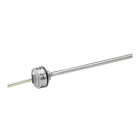
Allgemeine Beschreibung General description Die Baureihe TIM ist ein magnetostriktiver Wegaufnehmer The TIM series is a magnetostricitve transducer for direct, für direkte, genaue und absolute Messung von Wegen bzw. accurate measurement of travel in display- or feedback Längen in der Steuerungs-, Regelungs- und Messtechnik. -
Page 3: Elektrische Daten
TIM Montageanleitung TIM User Manual 3 Elektrische Daten 3 Electrical data Versorgungsspannung: Mobilelektronik Supply voltage: Mobile electronics el. Code 6 _ _ und 8 _ _: 12 / 24 VDC ( 8 ...32 VDC) el. Code 6 _ _ and 8 _ _: 12 / 24 VDC ( 8...32 VDC) el. -
Page 4: Montagehinweise
TIM Montageanleitung TIM User Manual Montagehinweise Instructions for installation 4.1 Bore diameter of piston rod 4.1 Bohrung der Kolbenstange The bore in the piston rod has to be laid out dependent on Die Bohrung in der Kolbenstange ist abhängig vom Druck the pressure and the operating speed. -
Page 5: Einbau & Installation
TIM Montageanleitung TIM User Manual Einbau / Installation Mechanische Ausführungen / Mechanical configuration Mechanische Ausführung / Mechanical configuration Flansch /Flange Code 305 Steckflansch / Plug-in flange Ø 48 mm Code 306 Schraubflansch / Screw flange M18x1,5 5.1 Steckflansch / Plug-in flange (Code 305) Kabelabgang / Cable connection * min. - Page 6 TIM Montageanleitung TIM User Manual Einbaubeispiel Kabelabgang / Installation example cable connection Einbaubeispiel Steckersystem M12x 1 / Installation example plug system M12x 1 ∅ Dk siehe / see 4.1 Einzelheit X, magnetisierbarer Werkstoff Einzelheit X, nichtmagnetisierbarer Werkstoff Einzelheit Y Detail Y Detail X, magnetizable material Detail X, non-magnetizable material Artikelnummer: 517991/07...
-
Page 7: Schraubflansch
TIM Montageanleitung TIM User Manual 5.2 Schraubflansch / Screw flange (Code 306) Kabelabgang / Cable connection * min. Biegeradius NT-Standardkabel: bei beweglicher Verlegung = 24 mm bei fester Verlegung = 5 mm min. bending radius NT standard cable: in case of movable assembly = 24 mm in case of fixed assembly = 5 mm Stecker M12x 1 / Plug M12x 1 Artikelnummer: 517991/07... - Page 8 TIM Montageanleitung TIM User Manual Einbaubeispiel / Installation example ∅ Dk siehe / see 4.1 Einzelheit X, nichtmagnetisierbarer Werkstoff Einzelheit X, magnetisierbarer Werkstoff Detail X, non-magnetizable material Detail X, magnetizable material ∅ 15,4x2,1 Einzelheit Y Detail Y Artikelnummer: 517991/07 Änderungen vorbehalten / Subject to change without notice 2014/11 Seite / page 8...
-
Page 9: Positionsgeber
Die Beschreibung der CANopen Schnittstelle sowie das The description of CANopen interface and the electronic elektronische Datenblatt (EDS) sind zum Download auf der data sheet (EDS) can be downloaded from Novotechnik Novotechnik Homepage unter Downloads/Gebrauchsanleitungen web site, see Downloads/Operating manuals.
Need help?
Do you have a question about the TIM Series and is the answer not in the manual?
Questions and answers