Advertisement
Available languages
Available languages
Quick Links
TM1 ユーザーズマニュアル / TM1 User manual
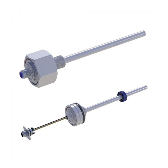
1 概要
TM1 シリーズは、制御、調整、測定アプリケーションに用いられる高精度の
磁歪変位トランスデューサです。
2 安全上のご注意
2.1 使用目的
トランスデューサは、機械またはシステムに設置することを目的としています。
コントローラー(PLC 等)と一緒に位置測定システムを構成し、この目的に
のみ使用できます。改造、不適切な使用、またはインストール手順の不遵守は、
保証の喪失につながり、責任請求を無効にします。
トランスデューサーのすぐ近くにある強い磁場または電磁界
は、誤った信号につながる可能性があります。
2.2 インストールと起動
トランスデューサは、関連するすべての安全規制を考慮して、資格のある担当
者が設置する必要があります。
トランスデューサの欠陥または故障の場合に人員と財産を保護するために必要
なすべての安全対策は、起動前に実行する必要があります。
2.3 接続を確認する
不適切な接続と過電圧は、トランスデューサを損傷する可能性があります。
システムの電源を入れる前に、必ず接続を注意深く確認してください。
2.4 システムの電源を入れる
システムは、特にトランスデューサのパラメータがまだ設定されて
いない制御システムの一部である場合、最初の電源投入時に制御されていない
動作を実行する場合があります。
したがって、これが人員や財産に危険が及ばないようにしてください。
2.5 測定値を確認する
トランスデューサの交換後は、手動モードでポジションマーカーの開始位置と
終了位置の出力値を確認することをお勧めします。
(トランスデューサは変更または製造公差の対象となります)
2.6 機能を確認する
トランスデューサとそれに関連するすべてのコンポーネントの機能を定期的に
チェックしてください。
2.7 故障誤動作
トランスデューサが適切に動作しない場合は、使用を停止し、不正使用から
保護してください。
2.8 アプリケーションの制限
当社の製品は、航空または航空宇宙用途では承認されておらず、原子力または
軍事、特に ABC 関連の用途での使用は許可されていません。
詳細については、利用規約をご覧ください。
3 インストール手順
関連するすべての寸法は図面を参照してください
Page 1
1 General description
This device is a magnetostrictive transducer for direct, precise
and absolute measurement of a linear position in control,
regulation and measuring applications.
2 Safety instructions
2.1 Intended use
The transducer is intended to be installed in a machine or system.
Together with a controller (e.g. PLC) it comprises a position measuring system and may only be
used for this purpose.
Unauthorized modifications, improper usage or nonobservance of the instructions for
installation will result in the loss of warranty and liability claims.
Strong magnetic or electromagnetic fields in close
proximity of the transducer may lead to faulty signals!
2.2 Installation & startup
The transducer must be installed by qualified personnel in consideration of all relevant
safety regulations.
All necessary safety measures to protect personnel and property in case of a transducer
defect or failure must be taken before startup.
2.3 Check connections
Improper connections and overvoltage can damage the transducer.
Please always check the connections carefully before turning on the system.
2.4 Turning on the system
The system may execute uncontrolled movements during first
turning-on mainly when the transducer is part of a control system
whose parameters have not yet been set. Therefore make sure that
hereof no dangers for personnel and property can result.
2.5 Check measured values
After replacement of a transducer, it is advisable to verify the output
values for start- and end position of the position marker in manual mode.
(transducers are subject to modification or manufacturing tolerances).
2.6 Check functionality
The functionality of the transducer system and all its associated
components should be regularly checked and recorded.
2.7 Failure malfunction
If the transducer system doesn 't operate properly, it should be taken
out of service and protected against unauthorized use.
2.8. Limitations for application
Our products are regularly not approved for aeronautic or
aerospace applications and are not allowed to be used in
nuclear or military, in particular ABC-relevant applications.
For more information see our Terms and Conditions.
3 Instructions for installation
All relevant dimensions see drawing
(https://www.novotechnik.de/en/downloads/cad-data).
Advertisement

Related Manuals for novotechnik TM1


Summary of Contents for novotechnik TM1
- Page 1 TM1 ユーザーズマニュアル / TM1 User manual 1 概要 1 General description TM1 シリーズは、制御、調整、測定アプリケーションに用いられる高精度の This device is a magnetostrictive transducer for direct, precise 磁歪変位トランスデューサです。 and absolute measurement of a linear position in control, regulation and measuring applications. 2 安全上のご注意 2 Safety instructions 2.1 使用目的...
- Page 2 TM1 ユーザーズマニュアル / TM1 User manual 3.1 ピストンロッドのボア径 3.1 Bore diameter of piston rod ピストンロッドのボアは、圧力と移動速度に応じて設計します。 The bore in the piston rod has to be laid out dependent on the 推奨ボア径 Dk ≥ 12.7mm。 pressure and the operating speed. ロッドの端は摩耗から保護する必要があります。 The recommended bore diameter amounts to Dk ≥ 12,7 mm.
- Page 3 TM1 ユーザーズマニュアル / TM1 User manual 3.3 一般情報 3.3 General information For horizontal mounting of the transducer with an electrical 電気測定範囲が 1000mm を超える変位トランスデューサを水平に設置する場合は、ロッド range longer than 1000 mm it is advisable to support or の端を支持することをお勧めします(ロッドの端にめねじがあるバリエーションをお勧めし attach the rod at the end (models with internal thread on rod end recommended).
- Page 4 CE conformity accord. to EN 61000-6-2/-3 CE 適合協定付き EN 61000-6-2 / -3 に準拠 Model: TM1 - _ _ _ _- _ _ _ - _ _ _ - 1_ _ モデル:TM1-_ _ _ _- _ _ _ --_ _ _ --1_ _...
- Page 5 TM1 ユーザーズマニュアル / TM1 User manual 5. インストレーション /Installation 5.1 プラグインフランジ /Plug-in flange(TM1-_ _ _ _-305-_ _ _-_ _ _) The transducer with Ø 48 mm flange has to be mounted in a フランジが Ø48mm のトランスデューサは、フィッティングボア Ø48H8 で fitting bore Ø 48 H8.
- Page 6 TM1 ユーザーズマニュアル / TM1 User manual プラグシステム M12x1 リード線 配置例 概略図 シリンダーヘッドスクリュー M4x4 でフランジプレートをシリンダーに取り付けます。 次に、コンタクトキャリアをフランジプレートにスナップします プラグシステム M12 × 1 シリンダー ピストン付きピストンロッド 面取り 1.5 × 15° 推奨 面取り 2.5 × 15° O リングシール 42.2 × 3 サポートリング付き 最小曲げ半径 NT 標準リード線: 可動アセンブリの場合 = 14mm 固定アセンブリの場合 = 7mm 詳細...
- Page 7 TM1 ユーザーズマニュアル / TM1 User manual 5.2 ねじフランジ M18 /Screw flange M18 (TM1-_ _ _ _-306-_ _ _-_ _ _) トランスデューサは、 六角フランジ(AF46)を使用してねじ込む必要があります。 The transducer has to be screwed in using the hexagon flange 締め付けトルクは 50Nm を超えないようにしてください。 (AF46). The fastening torque must not exceed 50 Nm! 付属の...
- Page 8 TM1 ユーザーズマニュアル / TM1 User manual プラグ M12x1 嵌合コネクタ:最大ねじ込みトルク 0.5 Nm プラグ付きモデルは、シリンダーの内外への設置に適しています (EMC、接地、ケーブルシールドは第 4 章を参照) 。 インターフェースと接続の割り当て アナログ出力 注文コードの例 電圧 電気接続 注文コード 供給電圧 エラー状態(電気測定範囲 L 外) 消費電力 負荷 <1W 負荷なし (引き下げる) 注文コードの例 電流 電気接続 エラー状態 (ケーブルブレーク GND) 注文コード 供給電圧 エラー状態(電気測定範囲 L 外)...
- Page 9 TM1 ユーザーズマニュアル / TM1 User manual 6.2 デジタル出力 / Digital Output 注文コードの例 電気接続 エラー状態(ケーブルの断線 GND) エラー状態(電気測定範囲外) 注文コード 供給電圧 消費電力 参照 <1.5 W(負荷なし) 通信なし 参照 プラグ 信号 接続なし 供給 Ub リングナット シールド カスタマイズされたケーブルは異なる色分けを示す場合があります! シールド付きツイストペアケーブル(STP)をお勧めします。 「接続しない」というラベルの付いた接続は分離する必要があります! 6.2.1 CANopen インターフェース 6.2.1 CANopen Interface CANopen インターフェースの説明...
Need help?
Do you have a question about the TM1 and is the answer not in the manual?
Questions and answers