Advertisement
Quick Links
TP1 Gebrauchsanleitung
TP1 User manual
1
Allgemeine Beschreibung
2
Sicherheitshinweise
2.1 Bestimmungsgemäße Verwendung
2.2 Installation & Inbetriebnahme
2.3 Anschlüsse prüfen
2.4 Einschalten des Systems
2.5 Messwerte prüfen
2.6 Funktionsfähigkeit prüfen
2.7 Funktionsstörung
2.8 Entsorgung
3
Elektrische Daten
4
Montagehinweis
5
Anschlüsse
6
Einbau und Installation
6.1 Wegaufnehmer
6.2 Positionsgeber
6.2.1 Z-TP1-P06
6.2.2 Z-TP1-P07
6.2.3 Z-TP1-P08
7
Elektrischer Anschluss
7.1 Code 101/103/108
7.2 Code 102/107
7.3 Code 201/203/205
7.4 Polbild
8
Schnittstellen und Anschlussbelegung
8.1 Impuls-Schnittstelle
8.2 SSI-Schnittstelle
8.3 Inkrementale Schnittstelle
8.4 Analoge Schnittstellen
8.5 IO-Link Schnittstelle
9
Spezifische Stecker auf Anfrage
9.1 6-pol. Flanschstecker
9.2 12-pol. Flanschstecker
9.3 5-pol. Flanschstecker
10
Teach-In Funktion
11
Versatz des Positionsgebers
11.1 Fehlermeldung Positionsgeber
12
Optionales Zubehör
13
Bestellcode
14
Produktidentifikation
402518885/14
2
2
2
2
2
2
2
2
2
2
3
3
3
4
4
5
5
5
5
6
6
6
6
7
8
8
8
9
10
10
11
11
11
11
11
13
13
14
14
14
Änderungen vorbehalten / Subject to change 2022/12
1
General description
2
Safety instructions
2.1 Intended conditions of use
2.2 Installation & startup
2.3 Check connections
2.4 Turning on the system
2.5 Check measured values
2.6 Check functionality
2.7 Failure malfunction
2.8 Disposal
3
Electrical data
4
Instruction for installation
5
Wiring
6
Mounting and installation
6.1 Transducer
6.2 Position marker
6.2.1 Z-TP1-P06
6.2.2 Z-TP1-P07
6.2.3 Z-TP1-P08
7
Electrical connection
7.1 Code 101/103/108
7.2 Code 102/107
7.3 Code 201/203/205
7.4 Contact arrangement
8
Interfaces and Connection Assignment
8.1 Impulse interface
8.2 SSI interface
8.3 Incremental interface
8.4 Analog output
8.5 IO-Link interface
9
Special connectors on request
9.1 6 pin flange connector
9.2 12-pin flange connector
9.3 5 pin flange connector
10
Teach-In function
11
Displacement of the position marker
11.1 Error conditions position marker
12
Optional accessories
13
Ordering code
14
Product identification
2
2
2
2
2
2
2
2
2
2
3
3
3
4
4
5
5
5
5
6
6
6
6
7
8
8
8
9
10
10
11
11
11
11
11
13
13
14
14
14
Seite 1
Advertisement

Related Manuals for novotechnik TP1 Series


Summary of Contents for novotechnik TP1 Series
- Page 1 TP1 Gebrauchsanleitung TP1 User manual General description Allgemeine Beschreibung Safety instructions Sicherheitshinweise 2.1 Bestimmungsgemäße Verwendung 2.1 Intended conditions of use 2.2 Installation & Inbetriebnahme 2.2 Installation & startup 2.3 Check connections 2.3 Anschlüsse prüfen 2.4 Einschalten des Systems 2.4 Turning on the system 2.5 Messwerte prüfen 2.5 Check measured values 2.6 Funktionsfähigkeit prüfen...
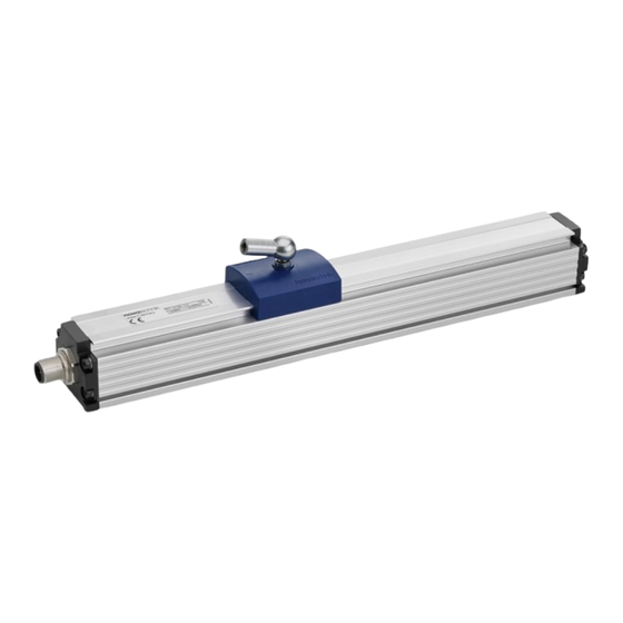
- Page 2 TP1 User manual Allgemeine Beschreibung General description The TP1 series is a magnetostricitve transducer for direct, Die Baureihe TP1 ist ein magnetostriktiver Wegaufnehmer accurate measurement of travel in display- or feedback für die direkte, genaue und absolute Messung von Wegen applications.
- Page 3 TP1 Gebrauchsanleitung TP1 User manual Elektrische Daten / Electrical data Versorgungsspannung / Supply voltage: 24 VDC (siehe auch Datenblatt / see also data sheet) Stromaufnahme / Current consumption: < 100 mA typisch, ohne Last / typical without load Lastwiderstand R / Load R ≥...
- Page 4 TP1 Gebrauchsanleitung TP1 User manual Einbau / Installation 6.1 Wegaufnehmer / Transducer Im Lieferumfang enthalten: Stahl-Spannklammern Z-46 inkl. Zylinderschrauben M5x20 Included in delivery: steel mounting clamps Z-46 incl. head cap screws M5x20 Optionales Zubehör Z-TP1-B03 2x Standard Befestigungsklammern Z-46 inkl. 4x Zylinderschrauben M5x20, Art.Nr.056029 Optional accessory Z-TP1-B03: 2x Standard mounting clamps Z-46 incl.
- Page 5 TP1 Gebrauchsanleitung TP1 User manual 6.2 Positionsgeber / Position markers Die im Datenblatt spezifizierten technischen Daten gelten, Unless otherwise stated, the technical data specified in the wenn nicht anders angegeben, bei der Verwendung eines data sheet applies to the use of a floating position marker. freien Positionsgebers.
- Page 6 TP1 Gebrauchsanleitung TP1 User manual Elektrischer Anschluss / Electrical connection 7.1 Steckverbinder M16x0,75 / Connector M16x0,75: Beispiel Bestellcode / Example ordering code: TP1- _ _ _ _ - _ _ _ - _ _ _ -101 (8-pol / 8 pin) Beispiel Bestellcode / Example ordering code: TP1- _ _ _ _ - _ _ _ - _ _ _ -108 (7-pol / 7 pin) Beispiel Bestellcode / Example ordering code:...
- Page 7 TP1 Gebrauchsanleitung TP1 User manual 7.4 Polbild / Contact arrangement (Sicht auf den Flanschstecker / front view to the flange connector) 8-pol. Flanschstecker / 8 pin flange connector M16x0,75 (IEC 130-9, DIN 45326) Beispiel Bestellcode / Example ordering code: TP1- _ _ _ _ - _ _ _ - _ _ _ -101 Zubehör / accessories : Kupplungsdose / straight connector EEM 33-84;...
- Page 8 TP1 Gebrauchsanleitung TP1 User manual Schnittstellen und Anschlußbelegung / Interfaces and Connection Assignment 8.1 Start-Stop- Impuls-Schnittstelle / Start-Stop- Impulse Interface Beispiel Bestellcode / Example ordering code: TP1- _ _ _ _ - _ _ _ -11 _ - _ _ _ Code elektr.
- Page 9 TP1 Gebrauchsanleitung TP1 User manual 8.3 Inkrementale Quadratur Schnittstelle / Incremental Quadrature interface Beispiel Bestellcode / Example ordering code: TP1- _ _ _ _ - _ _ _ -8_ _ - _ _ _ Code elektr. Abgang / code electr. connection Stecker 8-pol Stecker 8-pol mit Kabel Kabel / Cable...
- Page 10 (… IO-Link_Detail) sowie die Gerätebeschreibungs- (…IO-Link_Detail) and the device description file datei (IODD) sind zum Download auf der (IODD) can be downloaded from Novotechnik Homepage unter Novotechnik website, see Downloads/Operating Downloads/Gebrauchsanleitungen verfügbar manuals => Klick auf TP1 => Click on TP1 8.5.1 Anschlussbelegung / Pin assignment...
- Page 11 TP1 Gebrauchsanleitung TP1 User manual Spezifische Stecker auf Anfrage / Special connectors on request 9.2 12-pol. Flanschstecker / 12-pin flange connector 9.1 6-pol. Flanschstecker / 6 pin flange connector M16x0,75 (IEC 130-9, DIN 45326) M16x0,75 (IEC 130-9, DIN 45326 Beispiel Bestellcode / Example ordering code: Beispiel Bestellcode / Example ordering code: TP1- _ _ _ _ - _ _ _ -8_ _ -112 TP1- _ _ _ _ - _ _ _ -4_ _ -111...
- Page 12 TP1 Gebrauchsanleitung TP1 User manual 10.3 Positions-Programmierung 10.3 Position Programming (Nullpunkt und/oder Endpunkt einstellen) (setting up zero and/or end point) Die vollständige Programmierung muss innerhalb von 180 s The entire programming procedure must be completed abgeschlossen sein. within 180 s. Ausgang DIAG output...
- Page 13 TP1 Gebrauchsanleitung TP1 User manual 4 Beenden Teach-In 4 Finalize Teach-In First connect PROG to GND and within 0.5 s also connect DIAG to Zuerst PROG und innerhalb 0,5 s auch DIAG auf GND GND and leave both at least for 6 s connected to GND. legen und beide für mindestens 6 s auf GND lassen.
- Page 14 TP1 Gebrauchsanleitung TP1 User manual Schnittstelle / Interface Code Fehlermeldung / Error condition 0 … 20 mA ca. 20,1 mA 20 … 0 mA ca. 0,1 mA 4 … 20 mA ca. 20,1 mA 20 … 4 mA ca. 3,9 mA siehe Gebrauchsanleitung Linear_IO-Link_Detail Kapitel 5 (separates Dokument) IO-Link A_ _...
Need help?
Do you have a question about the TP1 Series and is the answer not in the manual?
Questions and answers